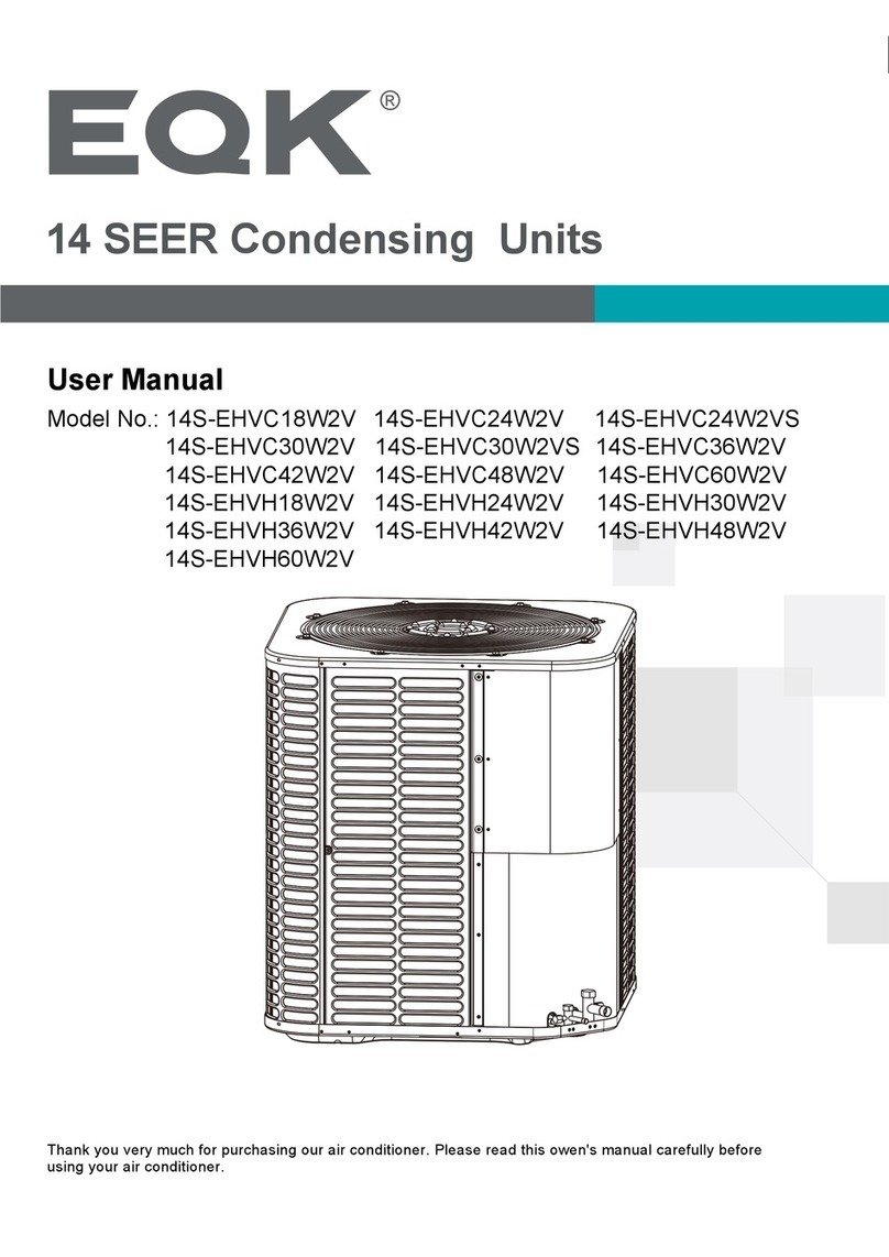
EQK EAC2H18R2C User manual

Thank you very much for purchasing our air conditioner. Please read this owen's manual carefully before
using your air conditioner.
Model No.: EAC2H18R2C
EAC4H36R2C
EAC3H24R2C
EAC5H42R2C
User Manual
Free Match Multi Zone Outdoor Units

Safety Instructions
Preparation before Use
Safety Precautions
Installation Instructions
Care and Maintenance
Protection
Energy Saving Tips
Troubleshooting
1
3
4
5
17
18
19
20
Identification of Parts
Display Introduction
21
22
THANK YOU
Congratulations on your purchase and welcome to the Family.
Your new Air Conditioner combines high-efficiency operation with portable convenience.
By following the operating and care instructions in this manual, your air conditioner will
provide you with many years of reliable service.
Please visit our website
www.eqkhvac.com
For any questions or Technical Support,

1
.
SAFETY INSTRUCTIONS
1. To guarantee the unit work normally, please read the manual carefully before
installation, and try to install strictly according to this manual.
2. Do not let air enter the refrigeration system or discharge refrigerant when moving the
air conditioner.
6. After installing, the consumer must operate the air conditioner correctly
according to this manual,keep a suitable storage for maintenance and moving of
the air conditioner in the future.
5. There must be an air-break switch.
4. Check the connecting cables and pipes carefully, make sure they are correct and firm
before connecting the power of the air conditioner.
T 3.15A or T 5A 250V
T 20A 250V
3. Properly ground the air conditioner into the earth.
9. Warning: Risk of electric shock can cause injury or death: Disconnect all remote
electric power supplies before servicing .
8. A residual current device(RCD)with the rating of above 10mA shall be
incorporated in the fixed wiring according to the national rule.
10.The best length of the connecting pipe between the indoor unit and outdoor
unit is less than 7.5 meters(24.6ft). It will affect the efficiency of the air conditioner
if the distance longer than that length.
12.This appliance can be used by children aged from 8 years and above and
persons with reduced physical, sensory or mental capabilities or lack of
experience and knowledge if they have been given supervision or instruction
concerning use of the appliance in a safe way and understand the hazards I
nvolved. Children shall not play with the appliance. Cleaning and user
maintenance shall not be made by children without supervision.
13.The batteries in remote controller must be recycled or disposed of properly.
Disposal of Scrap Batteries --- Please discard the batteries as sorted municipal
waste at the accessible collection point.
11. This appliance is not intended for use by persons (including children) with
reduced physical, sensory or mental capabilities, or lack of experience and
knowledge, unless they have been given supervision or instruction concerning
use of the appliance by a person responsible for their safety.Children should be
supervised to ensure that they do not play with the appliance.
Model
9K-12K(208/230V)
Fuse of Indoor unit
18K(208/230V)
24K-36K(208/230V)
Fuse of outdoor unit
T 3.15A or T 5A 250V
7. The Fuse of the unit:
T 3.15A or T 5A 250V
12K(115V) T 25A 250V
T 3.15A or T 5A 250V
9K(115V) T 25A 250V
T 15A 250V
T 30A 250V

2
SAFETY INSTRUCTIONS
15.If the supply cord is damaged, it must be replaced by the manufacturer, its
service agent or similarly qualified persons in order to avoid a hazard.
14.If the appliance is fixed wiring, the appliance must be fitted with means for
disconnection from the supply mains having a contact separation in all poles
that provide full disconnection under overvoltage category III conditions, and
these means must be incorporated in the fixed wiring in accordance with the
wiring rules.
18.The appliance shall not be installed in the laundry.
16.The appliance shall be installed in accordance with local electrical safety
regulations and National Electrical Codes(NEC).
17.The air conditioner must be installed by professional or qualified persons.
20.Regarding to maintenance, please refer to section “Care and Maintenance”.
19.Regarding to installation, please refer to section “Installation instructions”.

3
PREPARATION BEFORE USE
The air conditioner has an Auto-Restart function.
Each time after the remote control is replaced with new batteries or is energized, auto presetting
heat pump.If the air conditioner you purchased is a Cooling Only one, heat pump remote controller can also be
used.
remote control
Remote Control Presetting
Before using the air conditioner, be sure to check and preset the following.
Auto Restart Presetting
Hold down any button on remote control to activate the back light. It automatically shuts off 10 seconds
later.
Note: Back-light is an optional function.
Back-light Function (optional)of Remote Control
This appliance is made of recyclable or re-usable material. Scrapping must be carried out in
compliance with local waste disposal regulations. Before scrapping it, make sure to cut off the
mains cord so that the appliance cannot be re-used.
For more detailed information on handling and recycling this product, contact your local authorities
who deal with the separate collection of rubbish or the shop where you bought the appliance.
SCRAPPING OF APPLIANCE
This marking indicates that this product should not be disposed
with other household wastes throughout the North America. To
prevent possible harm to the environment or human health from
uncontrolled waste disposal, recycle it responsibly to promote
the sustainable reuse of material resources. To return your
used device, please use the return and collection systems or
contact the retailer where the product was purchased.
They can take this product for environmental safe recycling.
Note
Preset
Safeguarding the environment
When charging refrigerant into the system, make sure to charge in liquid state, if
the refrigerant of the appliance is R410A.Otherwise, chemical composition of
refrigerant (R410A) inside the system may change and thus affect performance
of the air conditioner.
According to the character of
pressure of the tube is very high, so be sure to be careful when you install and
repair the appliance.
refrigerant (R410A,the value of GWP is 2088), the
If the supply cord is damaged, it must be replaced by the manufacturer, its
service agent or similarly qualified persons in order to avoid a hazard.
The air conditioner must be installed by trained, qualified installers
and service mechanics.
The temperature of refrigerant circuit will be high, please keep the
interconnection cable away from the copper tube.

4
SAFETY PRECAUTIONS
Symbols in this Use and Care Manual are interpreted as shown below.
Be sure not to do.
Pay attention to such a situation.
Grounding is essential.
Warning: Incorrect handling could
cause a serious hazard, such as death,
serious injury, etc.
Do not use the power supply circuit
breaker or pull off the plug to turn it off
during operation. This may cause a fire
due to spark, etc.
Keep the power supply circuit breaker
or plug from dirt. Connect the power
supply cord to it firmly and correctly,
lest an electric shock or a fire break out
due to insufficient contact.
Use correct power supply in
accordance with the rating plate
requirement. Otherwise, serious
faults or hazard may occur or a
fire maybe break out.
Do not knit, pull or press the power supply
cord, lest the power supply cord be broken.
An electric shock or fire is probably caused
by a broken power supply cord.
Never insert a stick or similar obstacle
to the unit. Since the fan rotates at high
speed, this may cause an injury.
Do not repair the appliance by yourself.
If this is done incorrectly, it may cause an
electric shock, etc.
Turn off the appliance by remote control
firstly before cutting off power supply if
malfunction occurs.
It is harmful to your health if the cool air
reaches you for a long time. It is advisable
to let the air flow be deflected to all the room.
Prevent the air flow from reaching the gas
burners and stove.
Do not touch the operation buttons
when your hands are wet.
Do not put any objects on the outdoor
unit.
It is the user's responsibility to make the
appliance be grounded according to
local codes or ordinances by a licenced
technician.
OFF
OFF
ON
ON
ON/OFF
MODE FAN
SWINGSLEEPSUPER
SMART IFEELDIMMER
TIMER ON TIMER OFFCLOCK
ON
OFF
ON
OFF

5
INSTALLATION INSTRUCTIONS
Installation must be performed in accordance with the national wiring standards by authorized personnel only.
Above figure is only a simple presentation of the unit, it may not match the external appearance of the unit you purchased.
Distance from ceiling
Distance from wall
should be over 50mm/2in
Distance from the wall
should be over
200 mm/7.9in
should be over 50mm/2in
Distance from floor
over 2.4m/8ft.
should be
Distance from the obstacle
should be over 3.0m/10ft.
Indoor unit A
Installation diagram
Site Instructions
Site for Installing Indoor Unit
Installation of outdoor unit refers to the outdoor unit installation manual.
1. Where there is no obstacle near the air outlet and air can be
easily blown to every corner.
2. Where piping and wall hole can be easily arranged.
3. Keep the required space from the unit to the ceiling and wall
according to the installation diagram on previous page.
4. Where the air filter can be easily removed.
5. Keep the unit and remote controller 1m(3.28ft) or more apart
from television, radio etc.
6. Keep as far as possible from fluorescent lamps.
7. Do not put anything near the air inlet to obstruct it from air
absorption.
8. Install on a wall that is strong enough to bear the weight of t
he unit.
9. Install in a place that will not increase operation noise and
vibration.
10. Keep away from direct sunlight and heating sources. Do not place
flammable materials or combustion apparatuses on top of the unit.
Outdoor unit
Indoor unit
Pipe length is
20 meters
(65.4ft) Max.
be less than 10m (32.8ft)
Height should
Indoor unit is higher than outdoor unit

INSTALLATION INSTRUCTIONS
6
Suggested Tools
In order to install your air-conditioner more conveniently and safely, you might use
those special tools listed below.
Standard Wrench
Screw Driver
Hex Keys or Allen Wrenches
Adjustable/Crescent Wrench
Torque wrench
Drill & Drill Bits
Manifold and Gauges
Vacuum Pump
Clamp on Amp Meter
Level
Work Gloves
Safety Glasses
Pipe Cutter
Refrigerant Scale
R410A Flaring Tool
Micron Gauge
Hole Saw

INSTALLATION INSTRUCTIONS
7
Indoor unit installation
.Keep the mounting plate horizontal with a horizontal level or dropping line.
Mark the center of the indoor unit on mounting plate for future reference.
Tapping mounting plate to the wall with a minimum of five screws, evenly spaced to properly support
indoor unit weight.
1. Installing the Mounting Plate
MOUNTING BRACKET DIAGRAMS AND DIMENSIONS (Recommended)
Decide an installing location for the mounting plate according to the indoor unit location and piping
direction.
Mounting plate
Tapping screw
Note: The shape of your mounting plate may be different from the one above, but the installation method is similar.
Note: it is recommended to install screw anchors for sheet rock, concrete block, brick and such type of wall.
Note: the center of the mounting bracket may be not the center of the indoor unit.
Note: As the above figure shown, the six holes matched with tapping screw on the mounting plate must be used to
fix the mounting plate, the others are prepared.
For 738 Series Model, WIDTH:522mm/20.6in
For 808 Series Model, WIDTH:592mm/23.3in
200mm/7.9in or more to ceiling
50mm/2in
or more to wall50mm/2in
or more to wall
Indoor unit outline
FOR the Ordinary Mounting Plate
Pipe hole

INSTALLATION INSTRUCTIONS
8
MOUNTING BRACKET DIAGRAMS AND DIMENSIONS (Recommended)
For 908/1080 Series Model, WIDTH: 629mm/24.8in
For 1280 Series Model, WIDTH:820mm/32.3in
200mm/7.9in or more to ceiling
50mm/2in
or more to wall
50mm/2in
or more to wall
50mm/2in
or more to wall
50mm/2in
or more to wall
Indoor unit outline
Indoor unit outline
Pipe hole
Pipe hole
FOR the Ordinary Mounting Plate

INSTALLATION INSTRUCTIONS
9
Indoor unit installation
.Keep the mounting plate horizontal with a horizontal level or dropping line.
Mark the center of the indoor unit on mounting plate for future reference.
Tapping mounting plate to the wall with a minimum of five screws, evenly spaced to properly support
indoor unit weight.
MOUNTING BRACKET DIAGRAMS AND DIMENSIONS (Recommended)
Decide an installing location for the mounting plate according to the indoor unit location and piping
direction.
Note: The shape of your mounting plate may be different from the one above, but the installation method is similar.
Note: it is recommended to install screw anchors for sheet rock, concrete block, brick and such type of wall.
Note: the center of the mounting bracket may be not the center of the indoor unit.
Note: As the above figure shown, the six holes matched with tapping screw on the mounting plate must be used to
fix the mounting plate, the others are prepared.
FOR the Wooden Wall Mounting Plate

INSTALLATION INSTRUCTIONS
10
MOUNTING BRACKET DIAGRAMS AND DIMENSIONS (Recommended)
For 1280 Series Model, WIDTH:820mm/32.3in
200mm/7.9in or more to ceiling
50mm/2in
or more to wall50mm/2in
or more to wall
Indoor unit outline
Pipe hole
FOR the Wooden Wall Mounting Plate

INSTALLATION INSTRUCTIONS
REMOTE CONTROL
11
Indoor unit installation
Unit Model
Size A Size B Size C
mm/inmm/inmm/in
738 Series68/2.6833/1.370/2.7
808 Series70/2.7535/1.3870/2.7
908 Series137/5.440/1.5770/2.7
1080 Series170/6.740/1.5770/2.7
1280 Series64/2.5241.2/1.6270/2.7
Install a sleeve through the wall hole to keep the wall
tidy and clean.
Drill a hole in the wall. The hole should tilt a little
downward toward outside.
Decide the position of the hole for piping according to the
location of mounting plate.
2. Drill a Hole in wall for interconnecting Piping, Drain & Wiring
Table of Wall Hole Mounting size per Unit Size
Indoor
roodtuO
Wall hole sleeve
( hard polythene tube
prepared by user)
5mm
0.2in
(tilt downward)
Piping direction
1
2
3
4
Trough
Rubber plug
Drain
hole Drainage
structure
Note: When installing the pipe at the directions
1,2 or 4, saw the corresponding unloading piece
off the indoor unit base.
Note: Both sides drainage structure is standard. For both sides drainage structure, it can be chosen for right, left or both
sides drainage connection. If choosing both sides drainage connection, another proper drain hose is needed as there is
only one drain hose offered by factory. If choosing one side drainage connection, make sure the drain hole on the other
side is well plugged.
Unloading
piece
Saw the unloading piece
off along the trough
After connecting the piping , install the drain hose. Then connect the power cords. After connecting,
wrap the piping, cords and drain hose together with thermal insulation materials.
Put the piping (liquid and gas pipe) and cables through the wall hole from outside or put them through
from inside after indoor piping and cables connection is complete to connect to the outdoor unit.
Decide whether to saw the unloading piece off in accordance with the piping direction.(as shown below)
3. Piping and Drain Hose Connections to Indoor Unit

INSTALLATION INSTRUCTIONS
12
Piping Joints Thermal Insulation:
Wrap the piping joints with thermal
insulation materials and then wrap
with a vinyl tape.
Piping Thermal Insulation:
a. Place the drain hose under the piping.
b. Insulation material uses polythene foam over 6mm in thickness.
Note: Drain hose is prepared by user.
Do not arrange the drain pipe in a way that leaves it twisted, sticking
out or waving around. Do not immerse the end of it in water.
If an extension drain hose is connected to the drain pipe, make sure
to insulated when passing along the indoor unit.
When the piping is directed to the right, piping, power
Cord and drain pipe should be thermal insulated and
fixed onto the back of the unit with a piping fixer.
Thermal insulation
wrapped with vinyl type
A. Insert the pipe fixer to the slot. B. Press to hook the pipe fixer onto the base.
Base Base Base
Piping fixer Piping fixer Hook here
Insert here
drain
hose
drain
hose
large
pipe large
pipe
small
pipe
small
pipe
Small
pipe
Large pipe Thermal insulation
tube
Power cord
Drain hose
(prepared by user)
NOTE:
Dimensions are in “mm or inch” unless otherwise stated in the table.
Pipe size
Model
Liquid Side ( 1/4)φ6 or
9K-18K
18K
24K-36K
24K-36K
9K-12K
15~20N·m or 11~15ft-lbs
17 or 5/8
0.5 or 0.02
0.6 or 0.024
0.6 or 0.024
0.6 or 0.024
0.6 or 0.024
22 or 7/8
24 or 0.94
22 or 7/8
27 or 1.1
30~35N·m or 22~26ft-lbs
50~55N·m or 37~41ft-lbs
60~65N·m or 44~48ft-lbs
Liquid Side ( 3/8)φ9.53 or
Gas Side ( )φ12 or 1/2
Gas Side ( 3/8 )φ9.53 or
Gas Side ( 5/8)φ16 or
Torque Nut width Min.thickness
Indoor unit installation
c. Pre-tighten them with fingers at first, then use the wrenches.
If you don't hear the exhaust noise, please contact with the merchant.
a.Before unscrewing the big and the small sealing caps, press the small
sealing cap with the finger until the exhaust noise stops, and then loosen
the finger.
b. Connect indoor unit pipes with two wrenches. Pay special attention
to the allowed torque as shown below to prevent the pipes, connectors
and flare nuts from being deformed and damaged.
Piping Connection:
1.0 or 0.039
32 or 1.26
70~75N·m or 52~55ft-lbs
Gas Side ( /4)φ19 or 3
36K

13
INSTALLATION INSTRUCTIONS
Caution:
1. Never fail to have an individual power circuit specifically for the air conditioner. As for the method of
wiring, refer to the circuit diagram posted on the inside of the access door .
2. Comfirm that the cable thickness is as specified in the power source specification.
3. Check the wires and make sure that they are all tightly fastened after cable connection.
4. Be sure to install an earth leakage circuit breaker in wet or moist areas.
Cable Specifications
Attention:
The plug must be accessible even after the installation of the appliance in case there is a need
to disconnect it. If not possible, connect appliance to a double-pole switching device with
contact separation of at least 3 mm placed in an accessible position even after installation.
Connecting of the Cable
Indoor Unit
Connect the power cord to the indoor unit by connecting
the wires to the terminals on the control board individually
in accordance with the outdoor unit connection.
Note: For some models, it is necessary to remove the cabinet to
connect to the indoor unit terminal.
The figures in this manual are based on the external
view of a standard model. Consequently, the shape
may differ from that of the air conditioner you have
selected.
Chassis
Cabinet
Front panel
Terminal (inside)
Indoor unit
Power and Wiring
capacity(Btuh)Power cordPower connecting cord
TypeNormal cross-
sectional areasTypeNormal cross-
sectional areas
9K-12K(208/230V) SJ TW 3X16 AWG SJ TW 4X18 AWG
18K(208/230V) SJ TW 3X14 AWG SJ TW 4X18 AWG
24K-36K(208/230V) SJ TW 3X12 AWG SJ TW 4X18 AWG
9K,12K(115V) SJ TW 3X14 AWG SJ TW 4X18 AWG
Outdoor unit Different-diameter joint indoor unit
Connect pipes using different-diameter joint
If the diameter of connection pipe does not match the port size of outdoor unit, select
proper different-diameter joints in the accessory according to the following table.
Name Quantity Purpose
1Change pipe diameter from
1/4(6.35) to 3/8(9.52)
1Change pipe diameter from
3/8(9.52) to 5/8(15.88)
1Change pipe diameter from
3/8(9.52) to 1/2(12.7) mm

14
INSTALLATION INSTRUCTIONS
Make sure that the color of the wires in the outdoor unit and terminal No. are the same as those
of the indoor unit.
Wiring diagram
The diagram is reference only, and the actual terminal shall prevail.
Connecting
cable to outdoor unit
Terminal
1(N)
2(L)
3(SI)
Connecting
cable to outdoor unit
Terminal
1(N)
2(L)
3(SI)
For the multi interver
For the mono split
(1)208/230V
Warning: Before obtaining access to terminals, all supply circuits must
be disconnected.
Terminal
Indoor unit
Terminal
Outdoor unit
Power connecting cord
Green
White
Red
Black
1(N)
2(L)
3(SI)
Green
White
Red
Black
1(N)
2(L)
3(SI)
Power supply
L1
L2
GN
WHT
BLK
Terminal
Indoor unit
Terminal
Outdoor unit
Power connecting cord
YE/GN
Blue
Black
Black
Brown
1(N)
2(L)
3(SI)
YE/GN
Blue
Brown
2(N)
1(L)
4(SI)

15
INSTALLATION INSTRUCTIONS
Make sure that the color of the wires in the outdoor unit and terminal No. are the same as those
of the indoor unit.
Wiring diagram
The diagram is reference only, and the actual terminal shall prevail.
Connecting
cable to outdoor unit
Terminal
1(N)
2(L)
3(SI)
For the multi interver
( Currently unavailable. )
For the mono split
(2) 115V
Warning: Before obtaining access to terminals, all supply circuits must
be disconnected.
Terminal
Indoor unit
Terminal
Outdoor unit
Power connecting cord
Green
White
Red
Black
1(N)
2(L)
3(SI)
Green
White
Red
Black
1(N)
2(L)
3(SI)
Power supply
N
L
GN
WHT
BLK

16
INSTALLATION INSTRUCTIONS
Start-up
Test Operation
System Checks
Indoor Unit
Outdoor Unit
Perform test operation after completing gas leak and electrical safety check.
1.Turn on electrical disconnect to outdoor unit.
2.Push the “ON/OFF” button on Remote Controller to begin testing.
3.Push MODE button, select COOLING, HEATING, FAN mode to confirm all functions.
1.Conceal refrigerant pipes where possible.
2.Make sure drain hose slopes downward along entire length.
3.Ensure all refrigerant pipes and connections are properly insulated.
4.Fasten pipes to outside wall, when possible.
5.Seal and weatherproof wall hole which the interconnecting wires and refrigerant pipes pass through.
1.Do all Remote controller’s buttons function properly?
2.Do the display panel lights work properly?
3.Does the swing louver function properly?
4.Does the drain work?
1.Push the mode button to COOL and adjust the room setting to 61 deg. wait up to 3 minutes
from compressor time guard. Does compressor and outdoor fan turn on in cooling mode?
2.Push the mode button to HEAT and adjust the room setting to 85 ℉(30℃) deg. wait up to 3 minutes
for compressor time guard. Does compressor and outdoor fan turn on in heat mode?
℉(16℃)

17
CARE AND MAINTENANCE
It is necessary to clean the air filter
after using it for about 200 hours.
Clean it as follows:
Front panel maintenance Air filter maintenance
Never use volatile substance
such as gasoline or polishing
powder to clean the appliance.
Clean and reinstall the air filter.
Close the front panel again.
shock!
Electric
Dangerous!
Never sprinkle water onto the
indoor unit
Reinstall and shut the front panel.
Reinstall and shut the front panel by
pressing position "b" downward.
If the dirt is conspicuous,
wash it with a solution of
detergent in lukewarm water.
After cleaning, dry well in
shade.
Clean the air filter every two weeks
if the air conditioner operates in an
extremely dusty environment.
Stop the appliance and remove
the air filter.
1
23
1.Open the front panel.
2.Press the handle of the filter gently
from the front.
3. Grasp the handle and slide out the filter.
Grasp position "a" and
pull outward to remove the
front panel.
a
a
bb
Wipe with a soft
and dry cloth.
Use soft moisture cloth
to clean if the front panel
is very dirty.
soft cloth to
clean it.
Use a dry and
1.Turn off the air conditioner first.
2.Cut off the power supply by moving the
the power plug.

18
PROTECTION
Operating condition
Noise pollution
Install the air conditioner at a place that can bear its weight in order to operate more quietly.
Install the outdoor unit at a place where the air discharged and the operation noise would not annoy
your neighbors.
Do not place any obstacles in front of the air outlet of the outdoor unit lest it increases the noise level.
Features of protector
If all operation has stopped, press ON/OFF button again to restart, Timer should be set again if it has
been canceled.
The protective device will work at following cases.
Restarting the unit at once after operation stops or changing mode during operation, you need to wait for
3 minutes.
Connect to power supply and turn on the unit at once, it may start 20 seconds later.
Features of HEATING mode
Preheat
Defrost
At the beginning of the HEATING operation, the airflow from the indoor unit is discharged 2-5 minutes later.
In HEATING operation the appliance will defrost (de-ice) automatically to raise efficiency.
This procedure usually lasts 2-10 minutes. During defrosting, fans stop operation.
After defrosting completes, it returns to HEATING mode automatically.
Note: Heating is NOT available for cooling only air conditioner models.
1.
2.
Temperature Cooling operation Heating operation Drying operation
Indoor
temperature
max 90 32 81 27 90 32
min 70 (21 45 (764 18
Outdoor
temperature
max 115 (46 75 (24 ) 115 (46
min note 5(-15 70 (21
NOTE:
Operating temperature
*Optimum performance will be achieved within these operating temperature. If air conditioner is used outside of
the above conditions, the protective device may trip and stop the appliance.
*For Tropical (T3) Climate condition models,the outdoor max temperature is (55131 115instead of (46 .
*For some models, can keep cooling at (-5 51 outdoor ambient via unique design. Normally, optimum cooling
performance will be achieved above 07 12 . Please consult the merchant to get more information.
*For some models, can keep heating at (-5 51 -4outdoor ambient , some models heat at (-20 outdoor ambient
even heat at lower outdoor ambient
The temperature of some products is allowed beyond the range.In specific situation,please consult the
merchant.When relative humidity is above 80%, if the air conditioner runs in COOLING or DRY mode with door
or window opened for along time, dew may drip down from the outlet.
This manual suits for next models
3
Table of contents
Languages:
Other EQK Air Handler manuals
Popular Air Handler manuals by other brands

nilan
nilan Compact S CTS 602 manual

Ruck
Ruck ETA K 2400 V W Assembly and operating manual

Daikin
Daikin DV PTC 14 Series installation instructions

AAON
AAON H3 Series Installation operation & maintenance

TriangleTube
TriangleTube 1 Series Installation and maintenance manual

Arfit
Arfit TTP instruction manual

Frico
Frico PA2DR Original instructions

Fedders
Fedders Air Handler brochure

Enertech
Enertech EAD Series Installation, operation and maintenance manual

Trox Technik
Trox Technik X-CUBE X2 operating instructions

Lennox
Lennox CBX32MV-036 Configuration guide

BLAUBERG Ventilatoren
BLAUBERG Ventilatoren KOMFORT EC S5B 270 user manual