eqss OverWatch 6253 User manual
EQUIPMENT SAFETY SYSTEMS
75 Naxos Way, Keysborough 3173 Victoria Australia
P: +61 3 8770 6555
E: support@eqss.com.au
Haulotte Compact Slab
Installation Manual
REV 1.0
19/10/2020
Model6253 OverWatch™Installation Manual
Document # DO001252
|1 of 23|
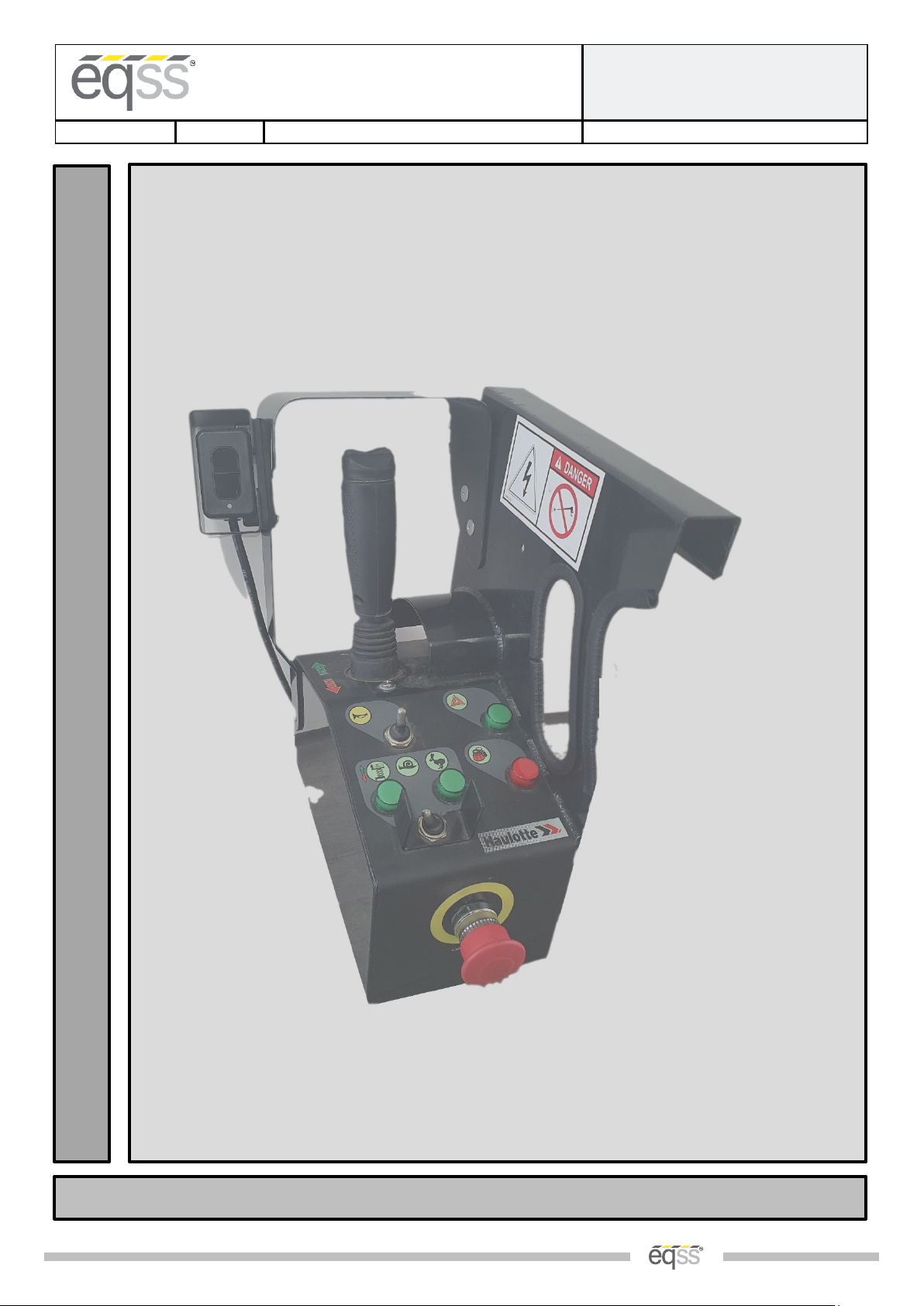
EQSS Model6253 – OverWatch™
Haulotte Compact Slab Scissor
I
N
S
T
A
L
L
M
A
N
U
A
L
** Failure to follow this installation manual will void warranty **

EQUIPMENT SAFETY SYSTEMS
75 Naxos Way, Keysborough 3173 Victoria Australia
P: +61 3 8770 6555
E: support@eqss.com.au
Haulotte Compact Slab
Installation Manual
REV 1.0
19/10/2020
Model6253 OverWatch™Installation Manual
Document # DO001252
|2 of 23|
AUTHORS:
Kieren Grogan,
Truong Bui, Jay
Nandakumar
AUTHORISED BY:
Kieren Grogan
CHECKED BY:
Andrew Donegan
DOCUMENT ABSTRACT:
This
Installation Manual details the manufacturer’s installation instructions for installing the Model6253 OverWatch™ on a
Haulotte
Compact Slab Scissor lift.
PRODUCT NAME:
Model6253
OverWatch™ Operator Detection System
REFERENCE DOCUMENTS:
DO000119
5 Model6253 OverWatch™ User Manual
CURRENT DOCUMENT REVISION:
1.0
REVISION INFORMATION:
•1.0 Initial Document Creation for installation on a Haulotte Compact Slab Scissor

EQUIPMENT SAFETY SYSTEMS
75 Naxos Way, Keysborough 3173 Victoria Australia
P: +61 3 8770 6555
E: support@eqss.com.au
Haulotte Compact Slab
Installation Manual
REV 1.0
19/10/2020
Model6253 OverWatch™Installation Manual
Document # DO001252
|3 of 23|
Important Information
Information contained in this publication regarding this device’s applications and the like, is provided only for your
convenience and may be superseded by updates. It is your responsibility to ensure that the application or our
equipment meets with your specifications.
EQUIPMENT SAFETY SYSTEMS MAKE NO REPRESENTATIONS OR WARRANTIES OF ANY KIND, WHETHER EXPRESSED OR
IMPLIED, WRITTEN OR ORAL, STATUTORY OR OTHERWISE, RELATED TO THE INFORMATION, INCLUDING, BUT NOT
LIMITED TO, IT’S CONDITION, QUALITY, PERFORMANCE, MERCHANTABILITY OR FITNESS FOR PURPOSE.
Equipment Safety Systems disclaims all liability arising from this information and its use. Use of Equipment Safety
Systems’ products as critical components in life support systems is not authorised except with express written
approval by Equipment Safety Systems. No licenses are conveyed, implicitly or otherwise, under any Equipment Safety
Systems intellectual property rights.
This is a class A product certified to AS/NZS CISPR 22:2006. In a domestic environment this product may
cause radio interference in which case the user may be required to take adequate measures.

EQUIPMENT SAFETY SYSTEMS
75 Naxos Way, Keysborough 3173 Victoria Australia
P: +61 3 8770 6555
E: support@eqss.com.au
Haulotte Compact Slab
Installation Manual
REV 1.0
19/10/2020
Model6253 OverWatch™Installation Manual
Document # DO001252
|4 of 23|
Table of Contents
Preparation........................................................................................................................................................ 5
Required Tools .............................................................................................................................................. 5
Installation Time............................................................................................................................................ 5
Installation Instructions..................................................................................................................................... 6
Operator Sensor............................................................................................................................................ 6
Control Module ........................................................................................................................................... 10
Post Installation Configuration........................................................................................................................ 15
Overview ..................................................................................................................................................... 15
Minimum system requirements.................................................................................................................. 15
Wi-Fi Connection & Web Page Access ........................................................................................................ 15
Machine Model Selection ........................................................................................................................... 16
Installation Test........................................................................................................................................... 17
Change Model Configuration ...................................................................................................................... 18
OEM Special Configuration.............................................................................................................................. 19
Overview ..................................................................................................................................................... 19
Wi-Fi Connection & OEM Web Page Access ............................................................................................... 19
OEM Password ............................................................................................................................................ 19
Settings........................................................................................................................................................ 20
Polarity and Input Style............................................................................................................................... 22
Bypass.......................................................................................................................................................... 22
Date and Time ............................................................................................................................................. 22
Connection Schematics ................................................................................................................................... 23

EQUIPMENT SAFETY SYSTEMS
75 Naxos Way, Keysborough 3173 Victoria Australia
P: +61 3 8770 6555
E: support@eqss.com.au
Haulotte Compact Slab
Installation Manual
REV 1.0
19/10/2020
Model6253 OverWatch™Installation Manual
Document # DO001252
|5 of 23|
Preparation
Required Tools
The OverWatch™ has been designed to be fitted using basic workshop tools. Shown below is a list of tools required
to complete the installation
Item
Tool / Description
1
Electric Drill
2
Centre punch
3
Hammer
4
Side Cutters
5
Drill 3.2mm
6
Drill 5.0mm
7
Metric sockets or spanners
8
Needle nose pliers
9
Screw drivers
Installation Time
The suggested time required to install the OverWatch™ is as detailed below
Task
Estimated Time (Minutes)
Open the operator control box
1
Drilling of all mounting holes for the various components
13
Mechanical assembly
10
Electrical assembly
10
Post installation system tests
10
Close the operator control box
1
Total
45
EQUIPMENT SAFETY SYSTEMS
75 Naxos Way, Keysborough 3173 Victoria Australia
P: +61 3 8770 6555
E: support@eqss.com.au
Haulotte Compact Slab
Installation Manual
REV 1.0
19/10/2020
Model6253 OverWatch™Installation Manual
Document # DO001252
|6 of 23|
Installation Instructions
Operator Sensor
Step
Description
Diagram
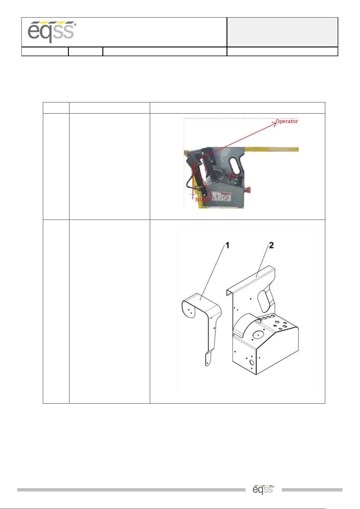
1.
The operator sensor should
be positioned as shown in the
image to the right.
2.
The platform control can be
separated into two
components:
(1) Platform control guard
plate
(2) Platform control main unit
EQUIPMENT SAFETY SYSTEMS
75 Naxos Way, Keysborough 3173 Victoria Australia
P: +61 3 8770 6555
E: support@eqss.com.au
Haulotte Compact Slab
Installation Manual
REV 1.0
19/10/2020
Model6253 OverWatch™Installation Manual
Document # DO001252
|7 of 23|
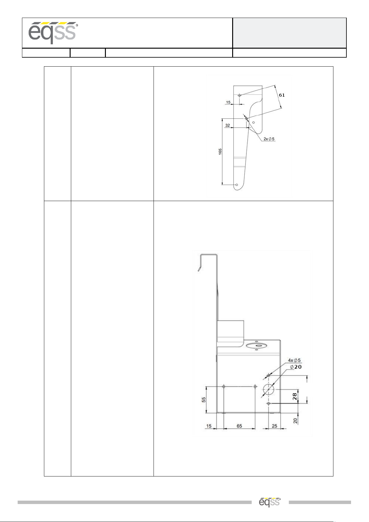
3.
On part (1),the platform
control guard plate, drill 2 X
5.00mm holes 61.00mm
apart in the locations shown
in the image.
4.
Remove the bottom cover of
platform control module. On
part (2),the platform control
main unit, drill the following,
referring to the diagram on
the right for hole locations:
2 X 5.00mm holes spaced
65.00mm apart (ECU Module)
2 X 5.00mm holes, spaced
55.00mm apart (Cable Gland
Guard)
1 X 20.00mm hole (Cable
Gland)
**Warning**
Keep the panel standing
upright during drilling to
avoid swarf going in the
middle of wiring and
electronics.
**Warning**
Clean swarf before going
further in the installation.
60

EQUIPMENT SAFETY SYSTEMS
75 Naxos Way, Keysborough 3173 Victoria Australia
P: +61 3 8770 6555
E: support@eqss.com.au
Haulotte Compact Slab
Installation Manual
REV 1.0
19/10/2020
Model6253 OverWatch™Installation Manual
Document # DO001252
|8 of 23|
5.
Mount the module in the
located position using the
supplied positioning wedges,
sensor guard, M4 washers,
nuts and bolts.

EQUIPMENT SAFETY SYSTEMS
75 Naxos Way, Keysborough 3173 Victoria Australia
P: +61 3 8770 6555
E: support@eqss.com.au
Haulotte Compact Slab
Installation Manual
REV 1.0
19/10/2020
Model6253 OverWatch™Installation Manual
Document # DO001252
|9 of 23|
6.
Install the cable gland and
cable gland guard in the holes
pre-drilled in step 4.

EQUIPMENT SAFETY SYSTEMS
75 Naxos Way, Keysborough 3173 Victoria Australia
P: +61 3 8770 6555
E: support@eqss.com.au
Haulotte Compact Slab
Installation Manual
REV 1.0
19/10/2020
Model6253 OverWatch™Installation Manual
Document # DO001252
|10 of 23|
Control Module
Step
Description
Diagram
1.
Using the supplied M4
screws and washers,
Mount the control module
inside the platform
control enclosure in the
location shown in the
image. Ensure connectors
are facing downward.
EQUIPMENT SAFETY SYSTEMS
75 Naxos Way, Keysborough 3173 Victoria Australia
P: +61 3 8770 6555
E: support@eqss.com.au
Haulotte Compact Slab
Installation Manual
REV 1.0
19/10/2020
Model6253 OverWatch™Installation Manual
Document # DO001252
|11 of 23|
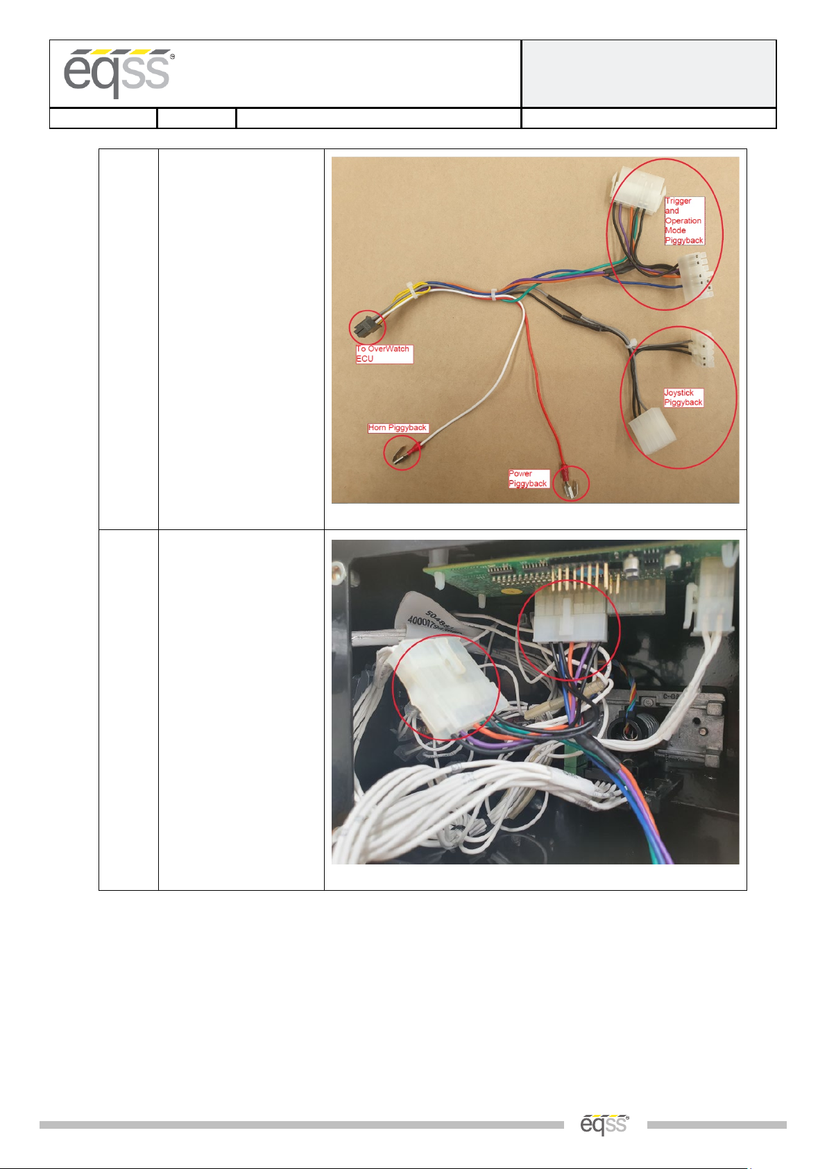
2.
Wiring connections are
made by the Plug and Play
loom AS001925.
3.
Trigger and Operation
Mode Connection:
Install the OverWatch
Harness Trigger and
Operation mode
Connectors at the location
shown in the photo.

EQUIPMENT SAFETY SYSTEMS
75 Naxos Way, Keysborough 3173 Victoria Australia
P: +61 3 8770 6555
E: support@eqss.com.au
Haulotte Compact Slab
Installation Manual
REV 1.0
19/10/2020
Model6253 OverWatch™Installation Manual
Document # DO001252
|12 of 23|
4.
Joystick Connection:
Install the OverWatch
Harness Joystick
Connectors at the location
shown in the photo.
5.
Power Connection:
At the back of the
Drive/Elevate Selection
Switch, install the
OverWatch Harness
Power piggyback cable to
the location shown in the
photo.
This will be taking power
from wire ID 11.

EQUIPMENT SAFETY SYSTEMS
75 Naxos Way, Keysborough 3173 Victoria Australia
P: +61 3 8770 6555
E: support@eqss.com.au
Haulotte Compact Slab
Installation Manual
REV 1.0
19/10/2020
Model6253 OverWatch™Installation Manual
Document # DO001252
|13 of 23|
6.
Horn Connection:
At the back of the horn
Switch, install the
OverWatch Harness Horn
piggyback cable to the
location shown in the
photo.
This connect to wire ID 36.
7.
Connect the 8-pin
connector from the
Operator Sensor, and the
12-pin connector from the
ECU harness into the
Control Module. Install
the cover back onto the
bottom of the joystick
enclosure.
EQUIPMENT SAFETY SYSTEMS
75 Naxos Way, Keysborough 3173 Victoria Australia
P: +61 3 8770 6555
E: support@eqss.com.au
Haulotte Compact Slab
Installation Manual
REV 1.0
19/10/2020
Model6253 OverWatch™Installation Manual
Document # DO001252
|14 of 23|
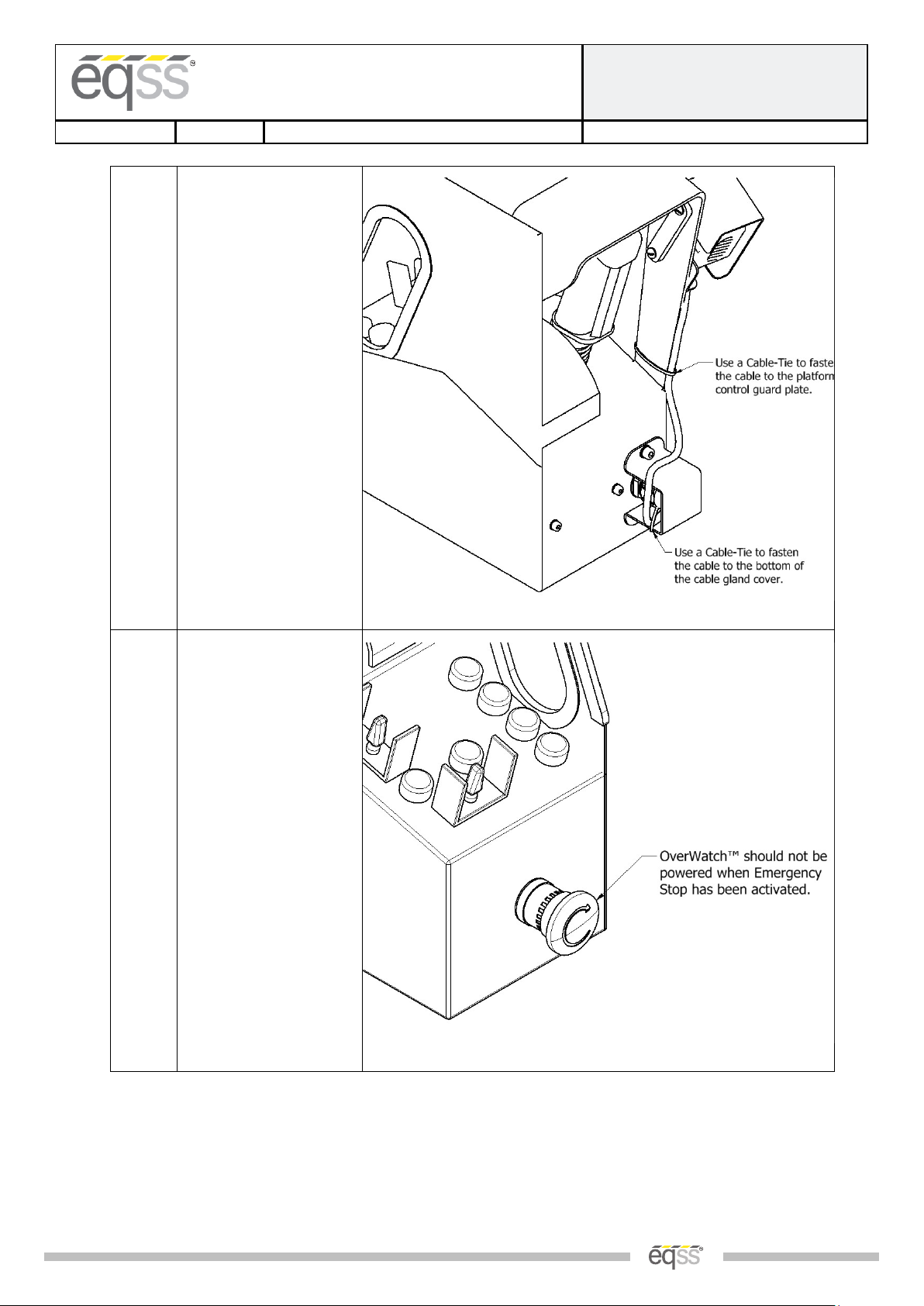
8.
Cable-Tie the cable from
the laser to the control
box in the two locations
shown in the diagram.
9.
After installation is
complete, power the
machine and press down
on the Emergency Stop.
While Emergency Stop is
active there should not be
power into the
OverWatch™ system. If
the OverWatch™ remains
powered, check if the
correct side of E-Stop has
been used for the
OverWatch™ power.

EQUIPMENT SAFETY SYSTEMS
75 Naxos Way, Keysborough 3173 Victoria Australia
P: +61 3 8770 6555
E: support@eqss.com.au
Haulotte Compact Slab
Installation Manual
REV 1.0
19/10/2020
Model6253 OverWatch™Installation Manual
Document # DO001252
|15 of 23|
Post Installation Configuration
Overview
After the OverWatch™ has been installed it must be configured with the parameters to suit the machine. Follow
the instructions below to configure the OverWatch™.
Minimum system requirements
Any smart phone, tablet or laptop that meets the following requirements:
•The device can connect to a Wi-Fi access point
•The device has an up to date web browser installed (2019 onwards). Firefox or Chrome are
recommended.
Wi-Fi Connection & Web Page Access
To enable the Wi-Fi connection on the OverWatch™ to complete the configuration follow the steps below.
1. Power down the platform control box with the ESTOP
2. Wait 10 seconds
3. Power up the platform control box with the ESTOP
4. While standing in the operator position, switch on the OverWatch™
5. As the welcome chime starts to play, cover the sensor. The LED will flash white then black to acknowledge.
6. Remove your hand from the sensor. The LED will flash white then black to acknowledge.
7. After covering then uncovering the sensor this way 2 more times, "Wi-Fi On" will be announced.
8. On your Wi-Fi enabled device (laptop, tablet, smartphone, etc), show the available wireless networks
9. Select the wireless network (starts with “overwatch”) to connect to the OverWatch™
10. When prompted, enter the password “12345678”
11. Open your preferred web browser (Chrome, Firefox, Safari, Edge)
12. Enter the following into the address bar http://192.168.4.1 to open the OverWatch™ main page

EQUIPMENT SAFETY SYSTEMS
75 Naxos Way, Keysborough 3173 Victoria Australia
P: +61 3 8770 6555
E: support@eqss.com.au
Haulotte Compact Slab
Installation Manual
REV 1.0
19/10/2020
Model6253 OverWatch™Installation Manual
Document # DO001252
|16 of 23|
Machine Model Selection
Follow the instructions below to configure the OverWatch™.
1. Select the Setup option
2. If there is a password field at the bottom of the page, follow the instructions in Change Model Configuration
to obtain the password and enter the password field
3. Select the EWP Model from the drop-down list and click Set
4. Click on Proceed to Test to begin the installation test
Haulotte Compact Slab Sci
Haulotte Compact Slab Scissor
Haulotte Compact Slab Scissor

EQUIPMENT SAFETY SYSTEMS
75 Naxos Way, Keysborough 3173 Victoria Australia
P: +61 3 8770 6555
E: support@eqss.com.au
Haulotte Compact Slab
Installation Manual
REV 1.0
19/10/2020
Model6253 OverWatch™Installation Manual
Document # DO001252
|17 of 23|
Installation Test
After the model configuration has been set or updated an Installation Test must be performed. This will ensure the
installation has been correctly performed and the OverWatch™ is functioning correctly.
Follow the instructions on the web page to complete the Installation Test.
EQUIPMENT SAFETY SYSTEMS
75 Naxos Way, Keysborough 3173 Victoria Australia
P: +61 3 8770 6555
E: support@eqss.com.au
Haulotte Compact Slab
Installation Manual
REV 1.0
19/10/2020
Model6253 OverWatch™Installation Manual
Document # DO001252
|18 of 23|
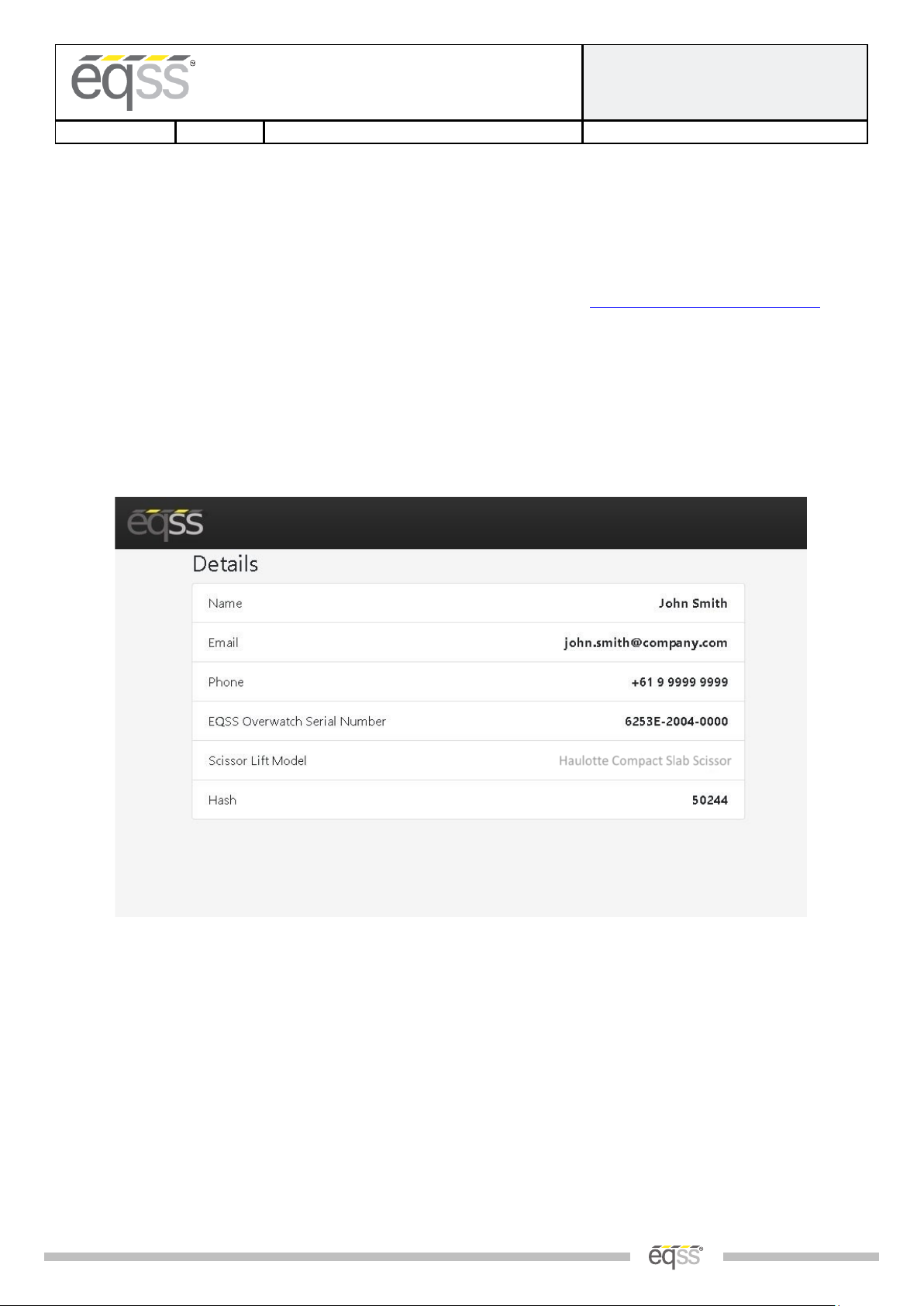
Change Model Configuration
To reconfigure the OverWatch™ for a different model requires an authorisation password to be supplied by a
service manager. The authorisation password is generated from the EQSS website. The EQSS website requires a
login username and password. If you are a service manager and don’t have a username and password, contact
EQSS to register. Follow the instructions below to obtain an authorisation password.
1. Open your preferred web and enter the following into the address bar http://www.eqss.com.au/overwatch
to open the Login page
2. Select Customer
3. Enter your username and password
4. Ask the service technician for the serial number shown on the Setup page or on the ECU module along with
the owner details of the EWP and complete the details form then click Generate Hash
5. Provide the 5-digit hash password to the service technician
Haulotte Compact Slab Scissor

EQUIPMENT SAFETY SYSTEMS
75 Naxos Way, Keysborough 3173 Victoria Australia
P: +61 3 8770 6555
E: support@eqss.com.au
Haulotte Compact Slab
Installation Manual
REV 1.0
19/10/2020
Model6253 OverWatch™Installation Manual
Document # DO001252
|19 of 23|
OEM Special Configuration
Overview
When installing the OverWatch™ on a new model there are number of parameters which need to be adjusted or
fine-tuned to suit a specific EWP model. The instructions below should be performed by the OEM of the EWP.
Once the OverWatch™ settings have been set and tested, they will then be supplied to EQSS to be used for other
installations.
Wi-Fi Connection & OEM Web Page Access
To enable the Wi-Fi connection on the OverWatch™ to complete the configuration follow the steps below.
1. Press the emergency stop button to power off the EWP
2. Cover the sensor with your hand
3. While the sensor is still covered release the emergency stop button to power on the EWP
4. Leave your head over the sensor until it says “Wi-Fi On”
5. On your Wi-Fi enabled device (laptop, tablet, smartphone, etc), show the available wireless networks
6. Select the wireless network starts with “overwatch” to connect to the OverWatch™
7. When prompted, enter the password “12345678”
8. Open your preferred web browser (Chrome, Firefox, Safari, Internet Explorer)
9. Enter the following into the address bar http://192.168.4.1/oem.html to open the OverWatch™ OEM
page
10. Follow the instructions in OEM Password below to obtain the OEM login password
OEM Password
The OEM settings are password protected. The OEM password is generated from the EQSS website. The EQSS
website requires a login username and password. If you are an OEM and do not have a username and password,
contact EQSS to register. Follow the instructions below to obtain an OEM password.
1. Open your preferred web and enter the following into the address bar http://www.eqss.com.au/overwatch
to open the Login page
2. Select OEM
3. Enter your username and password
4. Enter your name and contact details along with the serial number of the OverWatch™ then click Generate
Hash
5. Enter the 5-digit hash password into the OEM password field

EQUIPMENT SAFETY SYSTEMS
75 Naxos Way, Keysborough 3173 Victoria Australia
P: +61 3 8770 6555
E: support@eqss.com.au
Haulotte Compact Slab
Installation Manual
REV 1.0
19/10/2020
Model6253 OverWatch™Installation Manual
Document # DO001252
|20 of 23|
Settings
The OEM Settings page allows modification of all the OverWatch™ parameters. See the sections below for details
on each setting.
Setting Name
Description
Default
deltaseek
This specifies which of the previous lidar reading to
compare against the current one to calculate the
speed.
20
max_safe_velocity
This is the velocity threshold for the cutout in cm/s.
for drive mode. 95
max_safe_displacement
This is the maximum permitted distance in cm the
operator may be away from the calibration position in
drive mode.
50
max_safe_velocity_elevate
This is the velocity threshold for the cutout in cm/s. in
elevate mode. 75
max_safe_displacement_elevate
This is the maximum permitted distance in cm the
operator may be away from the calibration position in
elevate mode.
50
max_safe_velocity_neutral
This is the velocity threshold for the cutout in cm/s. in
neutral mode. 60
max_safe_displacement_neutral
This is the maximum permitted distance in cm the
operator may be away from the calibration position in
neutral mode.
40
fwddispadj
The coefficient to apply to the displacement when the
displacement is toward the sensor. -0.8
fwdveloadj
The coefficient to apply to the velocity when the
displacement is toward the sensor. -1
zone_obstruction
If the lidar sensor reading is below this, the lidar is
considered to be obstructed (with paint or thick coat
of dust) and the system is cutout until the obstruction
is cleared.
5
zone_minimum
Any lidar reading below this will trigger a cutout with
the message: “Operator Zone” 15
zone_maximum
Any lidar reading above this will trigger a cutout with
the message: “Operator Zone” 120
horn_count_max
The number of times the horn will sound when
alerting the operator if the trigger remains pressed
during the cutout.
2
horn_time_ms
The amount of time in milliseconds each individual
horn should play. 200
adc_elevate_threshold
For the elevate ADC input, a reading above this
indicates the EWP is in elevate mode. 2200
adc_drive_threshold
For the drive ADC input, a reading above this indicates
the EWP is in drive mode. 2200
Other manuals for OverWatch 6253
11
Table of contents


