Equalizer SG4TM User manual

Document Number: IM_SGM
Document Revision: 07
Document Revision Date: 14-DEC-2021
Document Language: English EN
Operation and Maintenance Manual
Secure-Grip Mechanical Flange Spreaders
SG4TM / SG6TM / SG11TM
To reduce the risk of injury, users must read and understand this document
before use.


IM_SGM_07 1
Contents
1. SAFETY ..................................................................................................................... 2
1.1 SAFETY PRECAUTIONS .................................................................................. 2
2. COMPLIANCE STATEMENT(S) ................................................................................ 4
3. FEATURES & COMPONENTS.................................................................................. 4
3.1 SG4TM, SG6TM, SG11TM FEATURES DIAGRAM .......................................... 4
3.2 SG4TM, SG6TM, SG11TM CAPABILITIES AND KIT CONTENTS .................. 5
4. TECHNICAL PRODUCT DATA ................................................................................. 8
4.1 SG4TM / SG6TM / SG11TM DIMENSIONS ..................................................... 8
4.2 SECURE GRIP FLANGE PULLER SPECIFICATIONS TABLE ......................... 9
5. OPERATION ............................................................................................................ 10
5.1 INITIAL SETUP AND INSPECTION ................................................................ 10
5.2 COLLET SELECTION ...................................................................................... 10
5.3 BOLT HOLE MEASUREMENT ........................................................................ 11
5.4 COLLET REPLACEMENT ............................................................................... 13
5.5 COLLET LEG SUB-ASSEMBLY - INSTALLATION ......................................... 13
5.6 TOOL INSTALLATION AND OPERATION...................................................... 14
6. STORAGE ................................................................................................................ 21
6.1 RECOMMENDED STORAGE .......................................................................... 21
6.2 LONG-TERM STORAGE - MAINTENANCE PLAN ......................................... 21
7. MAINTENANCE ...................................................................................................... 22
7.1 GENERAL MAINTENANCE............................................................................. 22
7.2 SG4TM/ SG6TM/ SG11TM DISASSEMBLY AND SERVICING...................... 22
8. PARTS LIST............................................................................................................. 24
9. TROUBLESHOOTING............................................................................................. 42
ANNEX 1 - SECURE GRIP TOOL RANGE OF APPLICATION ................................... 46
2IM_SGM_07
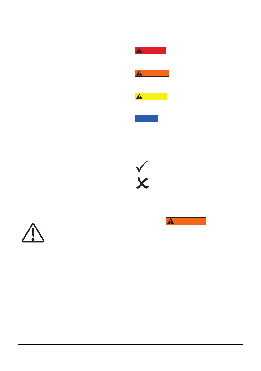
1. Safety
Indicates a hazardous
situation that, if not avoided, will result in
death or serious personal injury.
Indicates a hazardous
situation that, if not avoided, could result in
death or serious personal injury.
Indicates a hazardous
situation that, if not avoided, could result in
minor or moderate personal injury.
Indicates information
considered important, but not hazard
related (e.g. messages related to property
damage). Please note that the Safety Alert
Symbol will not be used with the signal
word.
DO: an illustration showing how the
tool should be used.
DON’T: an illustration showing an
incorrect way to use a tool.
1.1 Safety Precautions
Failure to observe and comply with the
following precautions could result in
death or serious personal injury. Property
damage could also occur.
• Read and completely understand the
safety precautions and instructions in this
manual before operating the SGM tools
or preparing them for use. Always follow
all safety precautions and instructions,
including those that are contained within
the procedures of this manual.
DANGER
WARNING
CAUTION
NOTICE
WARNING
Read all instructions carefully. Follow all
recommended safety precautions to avoid
personal injury as well as damage to the
product and / or damage to other property.
Equalizer cannot be responsible for any
damage or injury from unsafe use, lack of
maintenance, or incorrect operation. Do not
remove warning labels, tags, or decals. In
the event that any questions or concerns
arise, contact Equalizer or a local Equalizer
distributor for clarification.
Save these instructions for future use.
If you have never been trained on high-
pressure hydraulic safety, consult your
distributor or service center for information
about Equalizer Hydraulic Safety Courses.
This manual follows a system of safety
alert symbols, signals, words, and safety
messages to warn the user of specific
hazards. Failure to comply with these
warnings could result in death or serious
personal injury, as well as damage to the
equipment or other property.
The Safety Alert Symbol appears throughout
this manual. It is used to alert
you to potential physical injury
hazards. Pay close attention to
Safety Alert Symbols and obey
all safety messages that follow this symbol
to avoid the possibility of death or serious
injury.
Safety Alert Symbols are used in conjunction
with certain Signal Words that call attention
to safety messages or property damage
messages and designate a degree or level of
hazard seriousness. The Signal Words used
in this manual are DANGER, WARNING,
CAUTION, and NOTICE.

IM_SGM_07 3
• Be sure the operator has completed
safety induction training, specific to the
work surroundings. The operator should
be thoroughly familiar with the controls
and the proper use of the tool.
• Wear personal protective gear when
operating hydraulic equipment. Always
wear eye protection. Safety equipment
such as dust mask, non-skid safety
shoes, hard hats, gloves, or hearing
protection (used as appropriate) will
reduce personal injuries. The protective
clothing must not interfere with safe
operation of the tool or restrict the ability
to communicate with co-workers.
• Operatingprocedureswillvary,depending
on the system arrangement. Always
read, follow, and completely understand
all manufacturers’ instructions when
operating pumps, valves and all other
devices used with the SGM tools. Follow
all safety precautions contained in the
manufacturer’s manuals. Use only for
intended purpose.
• To minimize risk of personal injury, keep
hands and feet away from the tool and
workpiece during operation.
• Do not overload equipment.
• Immediately replace worn or damaged
parts. Use only genuine Equalizer parts
from approved distributors or service
centers. Equalizer parts have been
engineered and manufactured to be fit-
for-purpose.
• Use only a high-quality non-flammable
solvent for cleaning and degreasing
parts during wrench repair procedures.
To reduce the risk of fire or explosion, do
not use flammable solvents.
• Care should be taken when using the
lanyard to avoid entanglement with body
parts.
Failure to observe and comply with
the following precautions could result
in minor or moderate personal injury.
Property damage could also occur.
• Ensure components are protected from
external sources of damage, such as
excessive heat, flame, moving machine
parts, sharp edges, and corrosive
chemicals.
• Lubricate tools as directed in this manual
prior to operation. Use only approved
lubricants of high quality, following the
lubricant manufacturer’s instructions.
• Only use the designated anchor point
for fixing the lanyard. Do not attach the
lanyard to the plastic handle.
Failure to observe and comply with the
following precautions could result in
property damage and/or void the product
warranty.
• Always use Equalizer replacement parts.
• Always follow the inspection and
maintenance instructions contained in
this manual. Perform inspection and
maintenance after use, and at regular
intervals.
• Rope off working area and place warning
signs.
• To help ensure proper operation and
best performance, use of Equalizer oil is
strongly recommended
CAUTION
NOTICE

4IM_SGM_07
EU Declaration of Incorporation
These tools conform with the
requirements for CE.
•SG4TM •SG6TM •SG11TM
2. Compliance Statement(s)
Equalizer declares that this/ these product(s)
has/ have been tested and conforms to
applicable standards and is compatible to
all CE Requirements.
A copy of an EU Declaration of Incorporation
is enclosed with each shipment of this
product.
3. Features & Components
3.1 SG4TM, SG6TM, SG11TM Features Diagram
3
2
4
5
1
6
7
1. Actuator Assembly
2. Collet Holder Assembly
3. Leg Assemblies
4. Cantilever + Pins
5. Spring Plunger
6. Drive Nut
7. Spring Plunger
IM_SGM_07 5
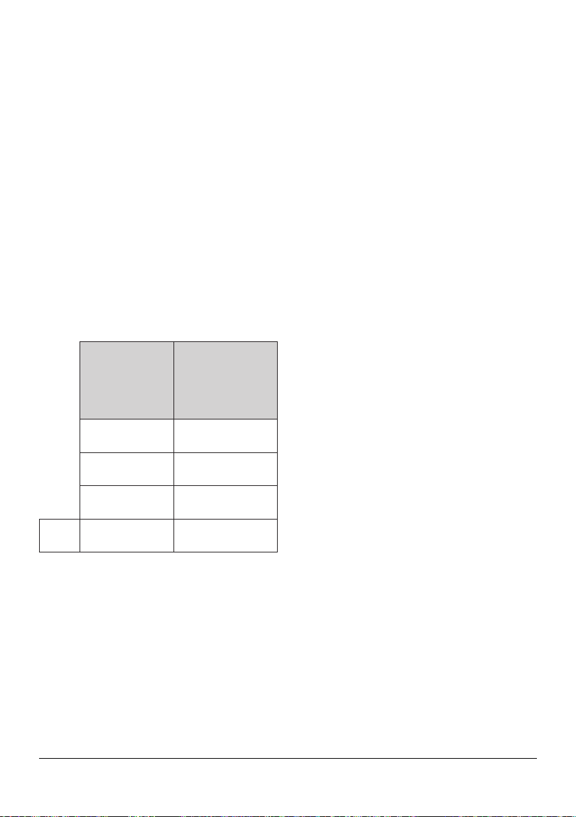
3.2 SG4TM, SG6TM, SG11TM
Capabilities and Kit Contents
3.2.1 SG4TM Tool Capabilities and
Kit Contents
Spreading Force:
With the maximum torque of 47 N·m
[35 ft·lb] applied, each SG4TM can apply
3.7T [37kN] spreading force.
It is recommended that tools are used in
pairs positioned 180° apart, giving 2 x 3.7T
= 7.4T [74kN].
The spreading force can be determined by
pre-setting the torque wrench. The torque
wrench settings will produce a spreading
force as set out below.
Torque Wrench
Setting Spreading Force
27N·m [20ft·lb] 2.2T [22kN]
34N·m [25ft·lb] 2.5T [25kN]
41N·m [30ft·lb] 3.3T [33kN]
Max. 47N·m [35ft·lb] 3.7T [37kN]
Spreading Distance:
0mm - 75mm [0"-2.95"]
3.2.2 SG4TM Kit Contents
Product Code: SG4TMSTD
1 x SG4TM Tool
1 x 150mm [6"] Vernier Calliper
1 x 3/8" Drive Torque Wrench and 16mm
Socket
1 x Safety Block
2 x M16 [5/8"] Collets
2 x M20 [3/4"] Collets
1 x Instruction Manual
1 x Carry-Case with foam inserts
Carry-Case Dimensions:
520mm x 375mm x 165mm
[20.5" x 14.8" x 6.5"]
Gross Kit Weight: 12.8kg [28.2lb]
Tool only weight: 4.5kg [9.9lb]
6IM_SGM_07
3.2.3 SG6TM Tool Capabilities and
Kit Contents
Spreading Force:
With the maximum torque of 108 N·m
[80 ft·lb] applied, each SG6TM can apply
6T [60kN] spreading force.
It is recommended that tools are used in
pairs positioned 180° apart, giving 2 x 6T
= 12T [120kN].
The spreading force can be determined by
pre-setting the torque wrench. The torque
wrench settings will produce a spreading
force as set out below.
Torque Wrench
Setting Spreading Force
54N·m [40ft·lb] 2.8T [28kN]
67N·m [50ft·lb] 3.5T [35kN]
81N·m [60ft·lb] 4.5T [45kN]
95N·m [70ft·lb] 5T [50kN]
Max. 108N·m [80ft·lb] 6T [60kN]
Spreading Distance:
0mm - 80mm [0"-3.15"]
3.2.4 SG6TM Kit Contents
Product Code: SG6TMSTD
1 x SG6TM Tool
1 x 150mm [6"] Vernier Calliper
1 x 3/8" Drive Torque Wrench and 21mm
Socket
1 x Safety Block
2 x M24 [7/8"] Collets
2 x M27 [1"] Collets
1 x Instruction Manual
1 x Carry-Case with foam inserts
Carry-Case Dimensions:
640mm x 540mm x 165mm
[25.2" x 21.3" x 6.5"]
Gross Kit Weight: 16.0kg [35.3lb]
Tool only weight: 7.5kg [16.5lb]

IM_SGM_07 7
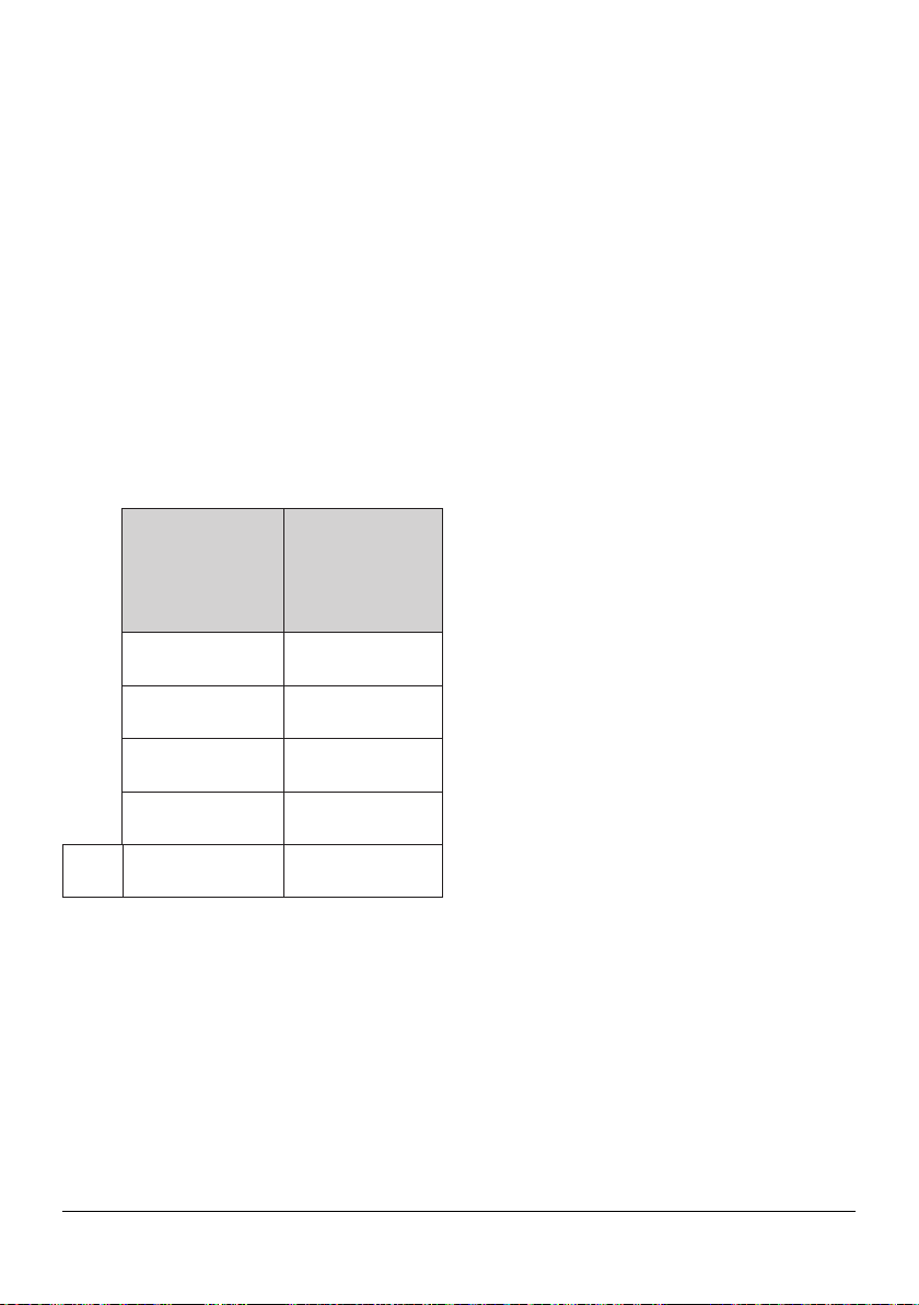
3.2.5 SG11TM Tool Capabilities and
Kit Contents
Spreading Force:
With the maximum torque of 120 N·m
[89ft·lb] applied, each SG11TM can apply
11T [110kN] spreading force.
It is recommended that tools are used in
pairs positioned 180° apart, giving 2 x 11T
= 22T [220kN].
The spreading force can be determined by
pre-setting the torque wrench. The torque
wrench settings will produce a spreading
force as set out below.
Torque Wrench
Setting
Spreading
Force
40N·m [30ft·lb] 3.7T [37kN]
60N·m [44ft·lb] 5.5T [55kN]
80N·m [59ft·lb] 7.4T [74kN]
100N·m [74ft·lb] 9.2T [92kN]
Max. 120N·m [89ft·lb] 11T [110kN]
Spreading Distance:
0mm - 90mm [0"-3.54"]
3.2.6 SG11TM Kit Contents
Product Code: SG11TMSTD
1 x SG11TM Tool
1 x 150mm [6"] Vernier Calliper
1 x 1/2" Drive Torque Wrench and 24mm
Socket
1 x Safety Block
2 x M30 [11/8"] Collets
2 x M33 [11/4"] Collets
2 x M36 [13/8"] Collets
1 x Instruction Manual
1 x Carry-Case with foam inserts
Carry-Case Dimensions:
640mm x 540mm x 165mm
[25.2" x 21.3" x 6.5"]
Gross Kit Weight: 20.0kg [44.1lb]
Tool only weight: 10.5kg [23.1lb]

8IM_SGM_07
4. Technical Product Data
4.1 SG4TM / SG6TM / SG11TM Dimensions
Tool Dimensions Closed
Tool Dimensions Open
Tool Dimensions Table
TOOL SG4TM SG6TM SG11TM
A398mm [15.67"] 468mm [18.42"] 516mm [20.31"]
B 190mm [7.48"] 245mm [9.65"] 250mm [9.84"]
C 182mm [7.2"] 252mm [9.92"] 263mm [10.35"]
D 75mm [2.95"] 80mm [3.15"] 90mm [3.55"]
E 385mm [15.16"] 444mm [17.48"] 462mm [18.2"]
F 48mm [1.89"] 52mm [2.05"] 60mm [2.36"]
B
A
D
E
C
F
IM_SGM_07 9
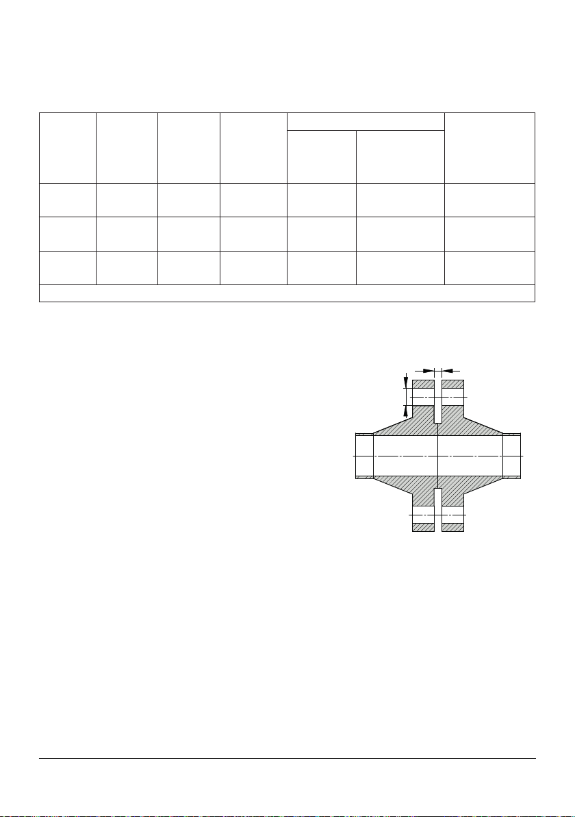
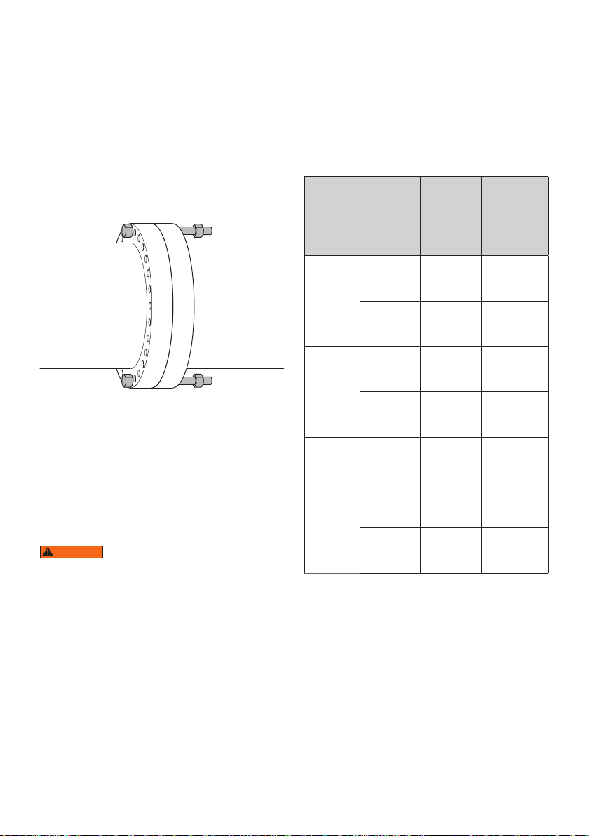
4.2 Secure Grip Flange Puller Specifications Table
(See Flange Dimensions for location of dimensions G + H)
Model
Number
Type
Maximum
Spreading
Force
Per Tool
[kN]
Spreading
Distance
Maximum
[mm]
Flange Dimensions Tool Weight
[kg]
Minimum
Access Gap
G
[mm]
Bolt-hole Diameter
Gap
H
[mm]
SG4TM
Mechanical
37.0
[4.16*]
75.0
[2.95in]
0
17.5 - 23.0
[0.69in - 0.91in]
4.5
[9.9lbs]
SG6TM
Mechanical
60.0
[6.74*]
80.0
[3.15in]
0
24.0 - 30.0
[0.94in - 1.18in]
7.5
[16.5lbs]
SG11TM
Mechanical
110.0
[12.36*]
90.0
[3.54in]
0
30.0 - 39.0
[1.18in - 1.54in
10.5
[23.1lbs]
* US tons
See Section 3.2.2 for case dimensions and kit contents
for SG4TM.
See Section 3.2.4 for case dimensions and kit contents
for SG6TM.
See Section 3.2.6 for case dimensions and kit contents
for SG11TM.
Flange Dimensions
G
H
10 IM_SGM_07
5. Operation
If the specification of the flange is unknown
then the vernier calliper supplied in the kit
should be used to determine the correct
collet.
TOOL COLLET
Minimum
bolt-hole
diameter
[mm]
Maximum
bolt-hole
diameter
[mm]
SG4TM
M16 [⅝"] 17.5mm
[0.69"]
19.5mm
[0.77"]
M20 [¾"] 20.5mm
[0.81"]
23mm
[0.91"]
SG6TM
M24 [⅞"] 24mm
[0.94"]
26.5mm
[1.04"]
M27 [1"] 27.5mm
[1.1"]
30mm
[1.18"]
SG11TM
M30
[1⅛"]
30mm
[1.18"]
33mm
[1.30"]
M33
[1¼"]
32mm
[1.26"]
36mm
[1.42"]
M36
[1⅜"]
35mm
[1.38"]
39mm
[1.54"]
5.1 Initial Setup and Inspection
The Secure Grip Tools spread flange joints
by engaging collets into the bolt-holes.
They can easily spread flange joints with
zero access gap, which traditional wedge-
type flange spreaders cannot spread.
The collets are suited to the sizes of the
bolt-holes and should be selected prior
to commencing work by following the
instructions in this section.
Replacement collets or different collets to
suit different bolt-hole sizes are available
from a local Equalizer distributor.
5.2 Collet Selection
It is important that the
correct size of collet is used. An undersized
collet could allow the collet holder to pull
through its bore. An oversized collet has
the potential to become jammed in the bolt-
hole.
The Secure Grip tools have a range of
collets which are applicable to the following
bolts and flange bolt-hole diameters shown
in the table below.
WARNING
IM_SGM_07 11
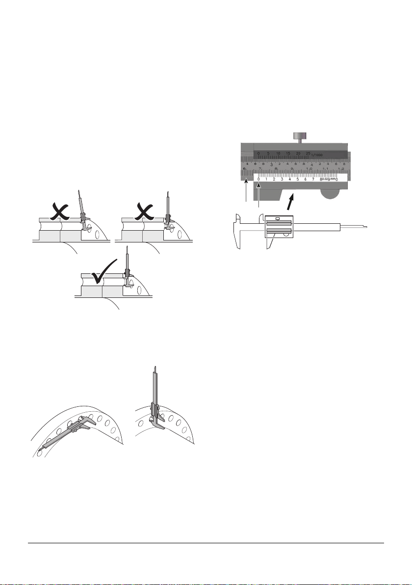
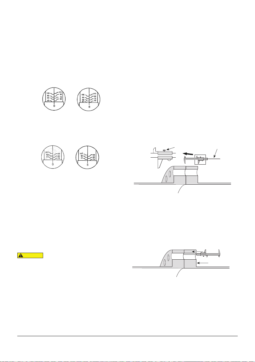
5.3 Bolt Hole Measurement
To ensure a true measurement is taken,
hold the vernier calliper:
• Square to the flange face,
• In the middle of the bolt-hole.
It is important that the vernier calliper is held
in the middle of the bolt-hole, and not held
at an angle to the flange face, nor used on a
bolt-hole which is worn, damaged or
distorted, as these actions may result in the
selection of an incorrect size of collet.
To confirm that the bolt-hole is round, take
two separate measurements with the vernier
calliper turned through 90° between
measurements.
To read the measurement from the vernier
calliper, scan along the desired scale from
left to right. In this example, the major figure
is 60mm, this is added to the minor figure
of 8 mm (indicated by where the vernier
scale aligns with the main scale), giving a
total measurement of 68mm.
With a bolt-hole size of 68mm, the operator
can determine which collet and tool is
appropriate to this flange by referring to
the table. For example: 68mm falls within
the 63mm minimum and 69mm maximum
bolt-hole sizes.
Therefore, collet identification is M64 / 2½"
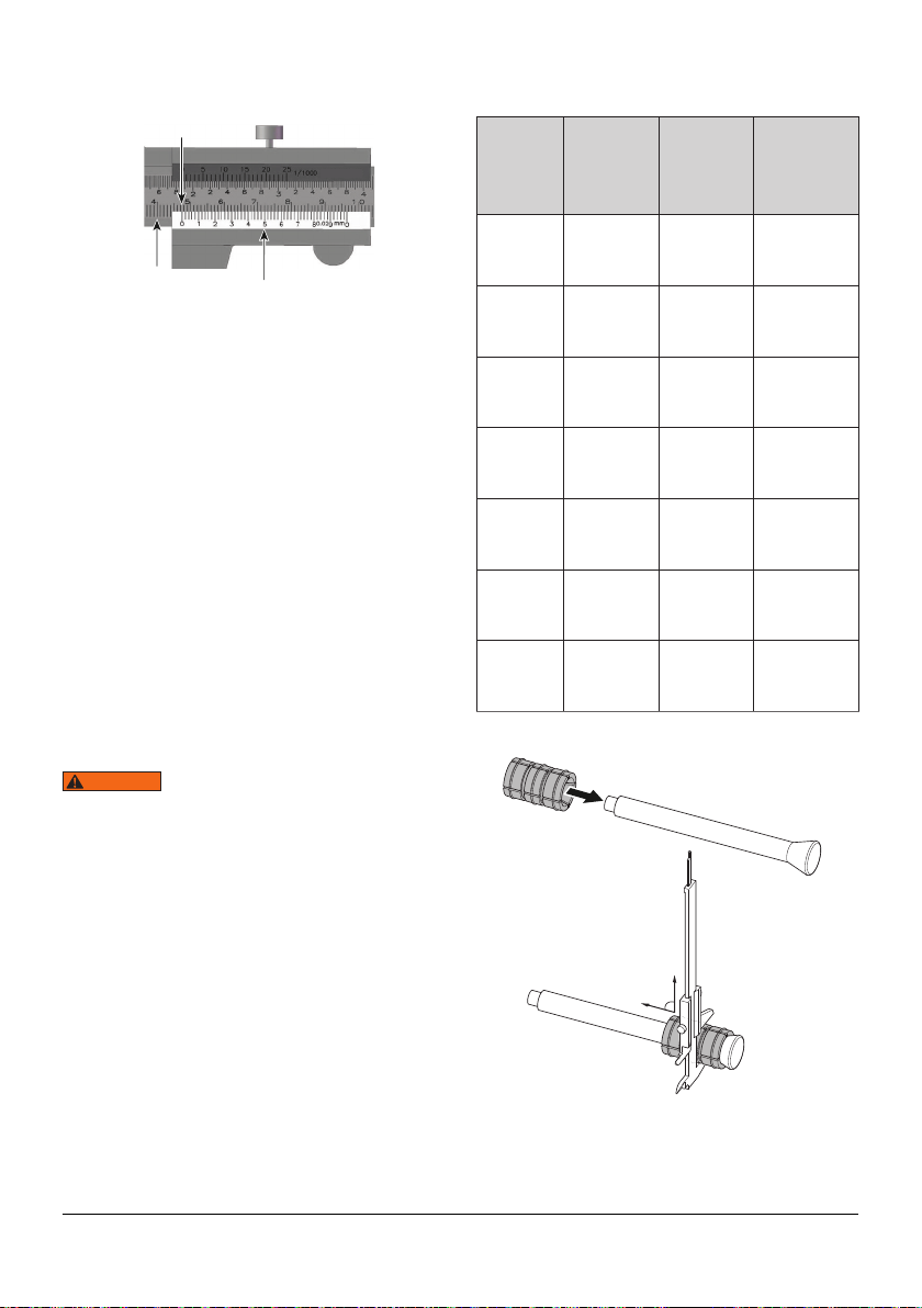
If the measurement contains fractions of a
millimetre the method of reading the vernier
calliper is slightly different. In this example,
the major figure is 40mm (read in the same
way as previously described). The minor
figure is 7mm (read to the left of the zero).
The fraction is 0.5mm (read from where the
vernier scale lines up with the main scale).
This gives a total measurement of 47.5mm.
Major
Figure Minor
Figure
12 IM_SGM_07
Each tool in the Secure Grip range comes
with the appropriate sizes of Collets for
that tool. If the Collet labelling is worn or
missing, then the Collet can be measured
to ensure that the correct size is selected.
An accurate measurement can only be
obtained with the Collet mounted on the
Collet Holder. To do this:
• Remove the Collet Head Assembly from
the tool and disassemble (see Section
5.4 for details)
• Slide the Collet over the Collet Holder
• Measure the centre section of the Collet
with the vernier calliper
• Identify the Collet using the chart below
and select the correct size for the flange.
The Secure Grip collets are
consumable items. The lifespan of a collet
will vary depending on the flange materials
with which it is used. To increase the lifespan
of the collets it is recommended that they
are flipped through 180° on the collet holder,
this will produce more even wear across the
four ridges on the outer profile of the collet.
See Section 5.4 for details on collet removal
and replacement.
Major
Figure Fraction
Minor Figure
WARNING
TOOL COLLET
Minimum
bolt-hole
diameter
[mm]
Maximum
bolt-hole
diameter
[mm]
16mm M16 [⅝"] 17.5mm
[0.69"]
19.5mm
[0.77"]
19mm M20 [¾"] 20.5mm
[0.81"]
23mm
[0.91"]
22.5mm
M24 [⅞"] 24mm
[0.94"]
26.5mm
[1.04"]
25.5mm
M27 [1"] 27.5mm
[1.1"]
30mm
[1.18"]
27mm M30
[1⅛"]
30mm
[1.18"]
33mm
[1.30"]
29.5mm
M33
[1¼"]
32mm
[1.26"]
36mm
[1.42"]
32.5mm
M36
[1⅜"]
35mm
[1.38"]
39mm
[1.54"]
90°
IM_SGM_07 13
5.4 Collet Replacement
Once the correct collet has been selected it
may be necessary to change the collet on
the SG4TM, SG6TM, or SG11TM tool:
Place the tool on its side on a work bench or
flat surface. Unscrew and remove the collet
nut.
Pull the Collet Spring Plunger Ring to
release and remove the collet head
assembly.
Remove the Drive Cone and Collet from the
Collet Holder. Replace the Collet with the
applicable size for the flange joint as
selected in Section 5.2.
Repeat the operation for the opposite Collet
Leg Sub-assembly.
Reverse the procedure to re-assemble the
tool. Care should be taken to ensure the slot
in the Collet holder is aligned with the collet
plunger.
5.5 Collet Leg Sub-Assembly -
Installation
The Collet Leg Sub-assemblies, as used in
tools SG4TM, SG6TM, SG11TM; should be
the first parts of the tool fitted to the flange
joint.
The Collets from each assembly should be
installed into the bolt-hole of the flanges on
either side of the joint to be spread. Care
should be taken to ensure that the Collets
are engaged in the correct position.

14 IM_SGM_07
If a spacer, blind or valve is installed
between the flanges, care should be taken
to ensure that the Collet or Collet Holder do
not extend beyond the flange bolt hole.
5.6 Tool Installation and Operation
Once the correct Collet has been
selected and mounted, tool operation can
commence.
The two halves of the mechanical Secure
Grip are inserted into opposing flange bolt-
holes.
Both drive nuts are tightened, locking the
tool into the flange bolt-holes.
The cantilever followed by the actuator are
swung and locked into position.
Drive Nut
Drive Nut
Cantilever
Actuator
Cantilever
Actuator
The actuator is tensioned, spreading the
flange to the maximum load capacity or
maximum spreading distance of the tool.
Before attaching the tool
ensure at least two flange bolts remain in
place 180 degrees apart with nuts loosened
sufficiently enough for flange work to be
carried out. These bolts will reduce lateral
flange movement during flange spreading.
Mechanical Tool Operation
The mechanical Secure Grip tools use
mechanical torque to advance the actuator
and spread the tool. The torque is applied
using the supplied torque wrench, enabling
accurate control of the force applied.
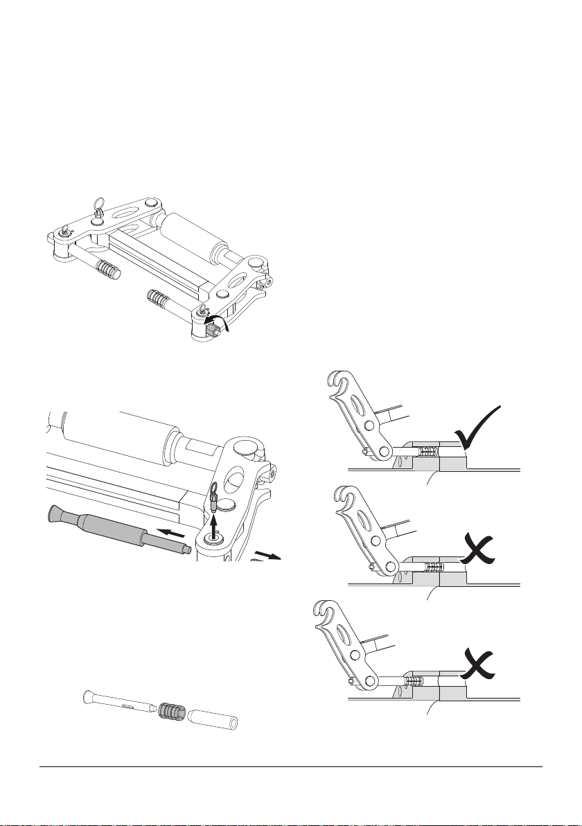
Torque Wrench Usage
Holding the Torque Wrench in one hand,
unlock the knurled handle by turning the
locking knob anti-clockwise.
Select the torque setting by turning the
knurled handle until the required torque
value is indicated.
WARNING
IM_SGM_07 15
For example, to set the Torque Wrench to
46N·m: turn the knurled handle until the 0
on the fine scale aligns with 40N·m on base
scale; now turn slightly further until the 6 on
the fine scale aligns with the central line.
Setting an imperial torque [in ft·lb] is done in
exactly the same way.
Lock the handle by turning the locking knob
clockwise.
Install the supplied socket onto the Torque
Wrench and attach to the tool.
Slowly and smoothly pull the handle,
gradually applying more force until you feel
or hear the Torque Wrench click, indicating
that the selected torque has been achieved.
Do not continue to apply force after the
Torque Wrench has clicked. Special care
should be taken when using low torque
settings.
Do not attempt to turn the
grip while it is locked. Do not turn the grip
more than one turn below the lowest scale
reading or above the highest scale reading.
CAUTION
Torque Wrench Care
Prior to storing the Torque Wrench, and
between use, leave the Torque Wrench with
its lowest torque setting selected.
To clean the Torque Wrench, wipe gently
with a damp cloth. Avoid using any detergent
or solvent as this may detrimentally affect
the factory-fitted internal lubrication of the
mechanism.
Measure the thickness of the flange using
the vernier calliper provided. Adjust the
depth gauge to one half of the flange total
length and lock the calliper in position by
tightening the locking screw.
Select a suitable bolt-hole in which to attach
the tool.
Insert the depth gauge part of the vernier
calliper into the bolt-hole keeping the base
of the calliper flush with the bolting face of
the flange.
Depth Gauge
Locking Screw
Bolting Face
16 IM_SGM_07
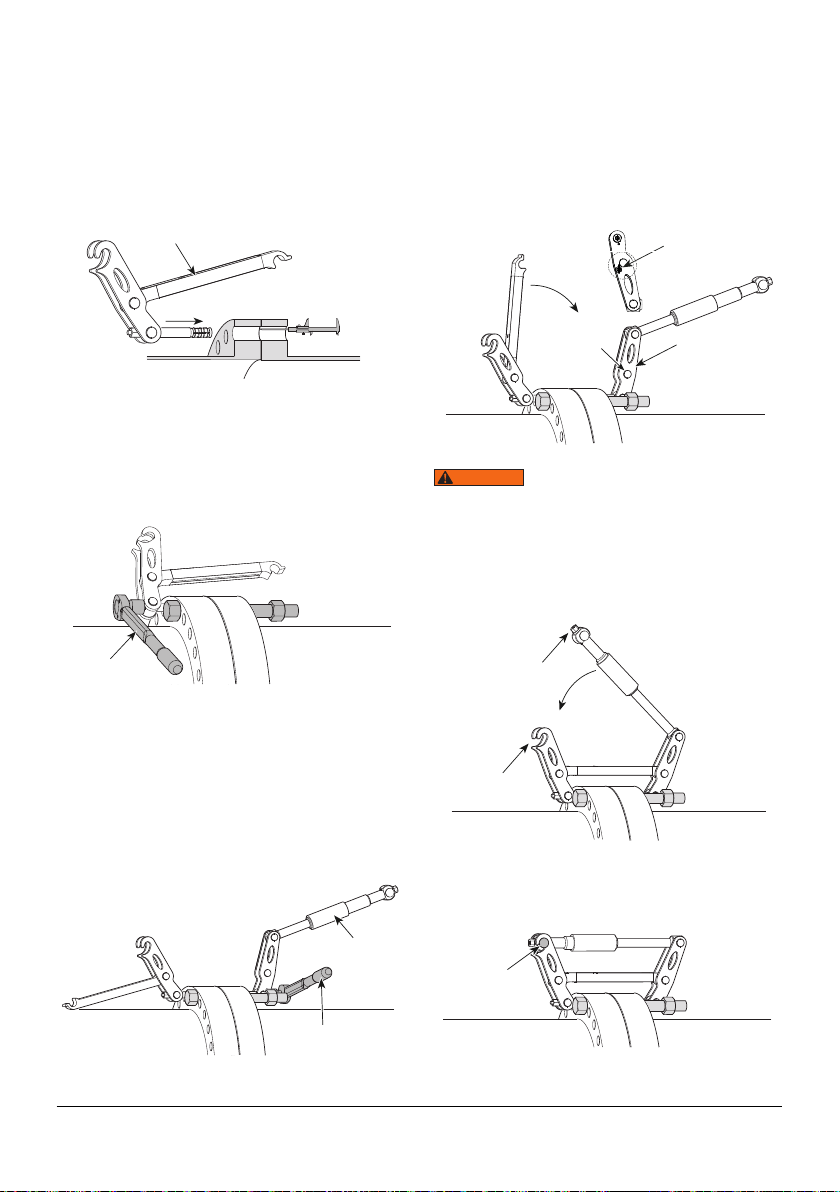
Insert the collet on the cantilever half of the
tool into the opposite end of the same bolt-
hole until it touches the end of the depth
gauge (so that the Collet is fully through one
flange but not entering the other).
Set the torque wrench to 30N·m [22ft·lb]
and tighten the drive nut until the torque
wrench clicks.
The cantilever half of the tool will now have
a secure hold in the bolt-hole.
Insert the Collet on the actuator half of the
tool into the bolt-hole until it touches the
collet on the cantilever half of the tool.
Tighten the drive nut with the torque wrench
pre-set to 30N·m [22ft·lb] until it clicks. The
actuator half of the tool will now have a
secure hold in the bolt-hole.
Cantilever
Torque Wrench
30 Nm (22 ft lb)
Actuator
Torque Wrench
30 Nm (22 ft lb)
Rotate the cantilever into position hooking
it over the cantilever pin in the actuator half
of the tool.
A click should be felt from the spring plunger
when it is locked fully home.
Operating the tool without
the cantilever fully locked into position may
result in personnel injury and damage to the
tool.
Ensure the actuator bolt is fully unscrewed,
then swing the actuator down into position.
Tighten the actuator bolt until the lugs on
the actuator union engage in the hooks on
the open legs.
Spring Plunger
(reverse view)
Cantilever
Pin Spring Plunger
WARNING
Open Leg
Hooks
Actuator
Bolt
Actuator
Lugs

IM_SGM_07 17
Select the bolt-hole 180° opposite the tool
that has just been attached and repeat the
above steps for the second tool.
If more than two tools are
being used they should be attached at an
equal spacing around the flange joint.
With the torque wrench set at 30 N·m
[22 ft·lb], tighten the actuator bolt on one
tool until the torque wrench clicks and then
torque the actuator bolt on the other tool.
Continue tensioning the actuator bolts until
the flange spreads or the torque wrench
clicks. Care should be taken to ensure the
actuator bolts maintain an equal tension on
both tools.
CAUTION
When the torque wrench clicks, stop and
increase the torque wrench setting by
10N·m [6.5ft·lb]. Continue to tension both
tools evenly until the flange spreads or the
torque wrench clicks.
If the torque wrench clicks, continue
increasing the torque wrench setting in
10 N·m [6.5 ft·lb] increments until the
maximum for the tool has been reached
(see table below).
If a greater spreading force
is required then further tools can be added
around the flange joint.
Overloading the tool will
cause tool failure which may result in
personal injury.
SG4TM SG6TM
SG11TM
Max. Torque
Wrench
Setting
Nm 47 108 120
ft lb 35 80 89
Max.
Spreading
Force
T 3.7 6 11
Actuator Bolt
Actuator Bolt
NOTICE
WARNING

18 IM_SGM_07
Continue spreading the flange until the
access gap required has been achieved or
until the maximum tool travel has been
reached.
The Secure Grip mechanical
tools are fitted with an internal mechanical
stop which limits the travel. Forcing the tool
to travel further will result in tool failure.
Tool Max. Distance
SG4TM 75mm [2.95"]
SG6TM 80mm [3.15"]
SG11TM 90mm [3.50"]
Once the flange has been separated
and prior to any maintenance work, the
safety blocks must be inserted between
the flanges. These are held in position by
removing two of the flange bolts that are
reinserted with the safety block positioned
in-between the flange faces.
Maximum
Spreading
Distance
WARNING
Do not allow fingers, hands
or other body parts to come into contact
with the flange or tools during operations.
Never place fingers, hands or other body
parts into the flange gap.
Following any maintenance works and prior
to closing the flange joint, the safety blocks
must be removed.
To reduce the load on each tool rotate the
actuator bolt one full rotation. Repeat this
on both tools in turn until the tools have no
load on them and the joint is closed.
The tools can then be removed from the
flange by reversing the installation
procedure.
5.6.1 Valve, Spade, or Blind
Removal, Installation, and
Operation
The Secure Grip mechanical tools are also
ideal for the removal and insertion of blinds,
spades and valves.
Equalizer can supply Short Collet Holder
(SCH) Kits for each tool that will increase its
relative stroke.
Safety
Block
Flange Bolt
WARNING
Other manuals for SG4TM
1
This manual suits for next models
2
Table of contents
Popular Industrial Equipment manuals by other brands


Sonny's
Sonny's Pendulum 807W Combo owner's manual

ABB
ABB HT611646 Operation manual

SKIOLD
SKIOLD UNI-MIX 1000 GM: 590061 instruction manual

VALLEY CRAFT
VALLEY CRAFT F88565C7 instruction manual

ITALVIBRAS GIORGIO SILINGARDI
ITALVIBRAS GIORGIO SILINGARDI E Series Technical handbook

Ulvac
Ulvac EGO-40M instruction manual


