SKF LINCOLN SP/SMB3 Series User manual

Version 01
951-230-018-EN
EN
Assembly instructions
ATEX ow limiters of series
SP/SMB3 and SP/SMB6

- 2 -
951-230-018-EN
Version 01
EN
The ignition hazard analysis conducted
in accordance with EN 80079-36 / -37
found that SKF flow limiters of series SP/
SMB3 and SP/SMB6 without electrical at-
tachments do not constitute own potential
sources of ignition. They consequently do not
fall under the scope of Directive 2014/34/EU
and thus do not bear explosion protection
marking.
To better incorporate the flow limiters into
the operator's explosion protection concept,
these flow limiters have been equipped with
an equipotential bonding terminal. No addi-
tional ignition source results from the com-
bination of the flow limiters described with
the signal transmitters specified in these
instructions, as they are to be classified as
simple electrical equipment in accordance
with EN 60079-14, No. 16.4.
These flow limiters are designated as ATEX
flow limiters in the following.
Classification of the explosion protection marking in the flow limiters in accordance with ignition hazard analysis in accordance with EN ISO 80079-36 /-37
Explosion protection marking in accordance with Directive 2014/34/EU

- 3 -
951-230-018-EN
Version 01
EN
Classification of the signal transmitters installed in the flow limiters
Classication as simple electrical equipment in accordance with EN 60079-14, No. 16.4
for use in potentially explosive atmospheres
as defined in the ATEX Directive 2014/34/
EU
We hereby confirm that the following signal
transmitters
Designation: 24-1072-2116
24-1072-2054
24-1072-2055
Year of manufacture: See type plate
are merely passive switching elements with
a max. internal capacitance of Ci=1nF and
an internal inductance of Li = 5µH
and in their entirety do not contain any own
ignition sources.
The signal transmitters 24-1072-2116,
24-1072-2054 and 24-1072-2055 are
passive elements that, for the purpose of
the intrinsically safe protection type "i," are
pieces of simple electrical equipment and
are treated in standard DIN EN 600079-
11, No. 5.7, when connected to an intrinsi-
cally safe electrical circuit with maximum
values:
Ui = 30 V
Pi = 1 W
I
i
= 100 mA
Simple electrical equipment of this kind is
independent of the device level.
Simple electrical equipment must be clearly
identifiable by permanent labeling. It can be
labeled by the constructor by some kind of
designation marking or coding that is pre-
ferred for the system.
SKF affixes this marking via the signal
transmitter’s blue connection cable or via a
blue screw union.
Hockenheim, 11/4/2019
Jürgen Kreutzkämper
Manager R&D Germany Stefan Schürmann
Manager R&D Hockenheim/Walldorf

- 4 -
951-230-018-EN
Version 01
Masthead
Training
SKF conducts detailed training in order to
enable the maximum safety and efficiency.
SKF recommends taking advantage of this
training. For information, contact the rel-
evant SKF service address.
Copyright
© Copyright SKF
All rights reserved.
Warranty
The instructions do not contain any infor-
mation on the warranty. This can be found in
our General Terms and Conditions.
Disclaimer of liability
The manufacturer shall not be held liable for
damage resulting from:
○Improper usage,
assembly, operation, configuration,
maintenance, repair, or accidents
○Improper reaction to malfunctions
○Unauthorized modifications to the
product
○Intentional or gross negligence
○Use of non-original SKF spare parts
The maximum liability for loss or damage
resulting from the use of our products is
limited to the purchase price. Liability for in-
direct damage of any kind is excluded.
Masthead
Manufacturer
SKF Lubrication Systems Germany GmbH
Address of manufacturer plants
Headquarters
Walldorf Plant
Heinrich-Hertz-Str. 2-8
69190 Walldorf
Germany
Tel: +49 (0) 6227 33-0
Fax: +49 (0) 6227 33-259
Berlin Plant
Motzener Straße 35/37
12277 Berlin
Germany
Tel. +49 (0)30 72002-0
Fax +49 (0)30 72002-111
Hockenheim Plant
2. Industriestraße 4
68766 Hockenheim
Germany
Tel. +49 (0)62 05 27-0
Fax +49 (0)62 05 27-101
E-mail: Lubrication-germany@skf.com
www.skf.com/lubrication

- 5 -
951-230-018-EN
Version 01
EN
Table of contents
Table of contents
Explosion protection marking in accordance with Directive 2014/34/EU ...2
Classification as simple electrical equipment ..............................................3
Masthead .....................................................................................................4
Explanation of symbols and signs ...............................................................7
1. Safety instructions .........................................................................9
1.1 General safety instructions....................................................................9
1.2 General behavior when handling the product .....................................9
1.3 Intended use..........................................................................................10
1.4 Foreseeable misuse..............................................................................10
1.5 Painting plastic components ...............................................................11
1.6 Modifications to the product................................................................11
1.7 Prohibition of certain activities............................................................11
1.8 Inspections prior to delivery ................................................................11
1.9 Referenced documents ........................................................................12
1.10 Markings on the product......................................................................12
1.11 Notes on the type plate ........................................................................12
1.12 Note on CE marking..............................................................................13
1.13 Persons authorized to use the product ..............................................13
1.13.1 Operator...........................................................................................13
1.13.2 Qualified mechanic .........................................................................14
1.13.3 Qualified electrician ........................................................................14
1.13.4 Specialist in maintenance and servicing in potentially
explosive atmospheres ..................................................................14
1.14 Explosion protection marking in accordance with
Directive 2014/34/EU..........................................................................13
1.15 Instruction of outside fitters ................................................................14
1.16 Provision of personal protective gear.................................................14
1.17 Operation ...............................................................................................14
1.18 Emergency shutdown ..........................................................................15
1.19 Transport, assembly, maintenance, malfunction,
repair, shutdown, disposal ...................................................................15
1.20 First start-up, daily start-up ...............................................................16
1.21 Cleaning .................................................................................................17
1.22 Special safety instructions regarding explosion protection .............17
1.23 Nullification of ATEX approval..............................................................19
1.24 Operation in potentially explosive atmospheres ...............................19
1.25 Obligations of the operator..................................................................20
1.25.1 Identification of hazards.................................................................20
1.25.2 Explosion protection measures.....................................................20
1.26 Residual risks ........................................................................................21
1.27 Residual ATEX risks...............................................................................22
2. Lubricants ................................................................................... 24
2.1 General information .............................................................................24
2.2 Selection of lubricants..........................................................................24
2.3 Material compatibility...........................................................................25
2.4 Aging of lubricants................................................................................25
3. Overview, functional description ................................................ 26
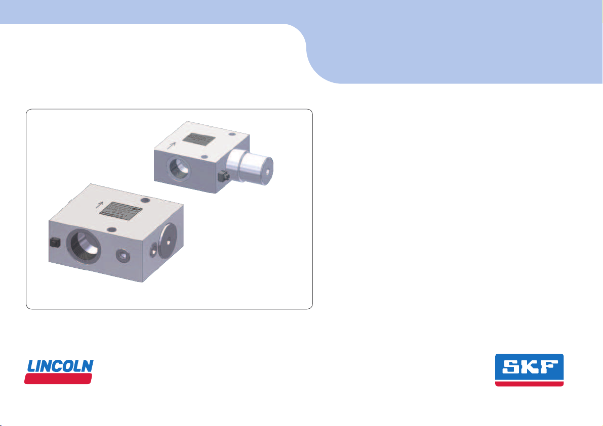
3.1 ATEX Flow limiter SP/SMB3 ................................................................26
3.1.1 Type designation.............................................................................27
3.2 ATEX Flow limiter SP/SMB6 ................................................................28
3.2.1 Type designation.............................................................................29
3.3 Functional description of a flow limiter ..............................................30
4. Technical data ............................................................................. 31
4.1 General technical data SP/SMB3 and SP/SMB6...............................31
4.2 Flow limiter SP/SMB3 ..........................................................................32
4.3 Flow limiter SP/SMB6 ..........................................................................32
4.4 Plug-in nozzle table SP/SMB3............................................................33
4.5 Plug-in nozzle table SP/SMB6............................................................34
4.6 Signal transmitter.................................................................................35

- 6 -
951-230-018-EN
Version 01
EN Table of contents
5. Delivery, returns, storage ........................................................... 36
5.1 Delivery..................................................................................................36
5.2 Return shipment...................................................................................36
5.3 Storage...................................................................................................36
6. Assembly ..................................................................................... 37
6.1 General information .............................................................................37
6.2 Minimum mounting dimensions.........................................................38
6.3 Assembling the flow limiters SP/SMB3 and SP/SMB6 ....................39
6.3.1 Assembly drawing SP/SMB3.........................................................40
6.3.2 Assembly drawing SP/SMB3 with
signal transmitter 24-1072-2116 ..............................................41
6.3.3 Assembly drawing SP/SMB3 with
signal transmitter 24-1072-2054 ..............................................42
6.3.4 Assembly drawing SP/SMB3 with
signal transmitter 24-1072-2055 ..............................................43
6.3.5 Assembly drawing SP/SMB6.........................................................44
6.3.6 Assembly drawing SP/SMB6 with
signal transmitter 24-1072-2116 ..............................................45
6.4 Signal transmitter connection.............................................................46
6.4.1 General information .......................................................................46
6.4.2 Application.......................................................................................46
6.4.3 Designs ............................................................................................47
6.4.4 Signal transmitter 24-1072-2116..............................................47
6.4.5 Signal transmitter 24-1072-2055 .............................................49
6.4.6 Signal transmitter 24-1072-2054..............................................51
6.5 Establishing equipotential bonding.....................................................52
6.6 Lubrication line connection .................................................................53
7. First start-up .............................................................................. 54
7.1 Inspections before first start-up .........................................................54
7.2 Inspections during first start-up.........................................................54
8. Operation .................................................................................... 55
8.1 Temporary shutdown ...........................................................................55
8.2 Permanent shutdown and disposal....................................................55
8.3 Disposing of dismantled parts.............................................................55
9. Cleaning ...................................................................................... 56
9.1 Cleaning agents.....................................................................................56
9.2 Exterior cleaning ...................................................................................56
9.3 Interior cleaning....................................................................................56
10. Maintenance ............................................................................... 57
10.1 Maintenance for flow limiters..............................................................57
10.2 Maintenance schedule .........................................................................57
10.3 Replacing a plug-in nozzle..................................................................59
10.3.1 Changing the plug-in nozzle SP/SMB3........................................59
10.3.2 Changing the plug-in nozzle SP/SMB6........................................60
11. Malfunctions, causes, and remedies ........................................... 62
12. Repairs ........................................................................................ 63
12.1 Replacement of signal transmitter .....................................................63
12.1.1 Replacement of signal transmitter 24-1072-2116 ..................64
12.1.2 Replacement of signal transmitter 24-1072-2054 ..................65
12.1.3 Replacement of signal transmitter 24-1072-2055 ..................66
13. Shutdown, disposal .................................................................... 67
13.1 Temporary shutdown ...........................................................................67
13.2 Permanent shutdown, disassembly ...................................................67
13.3 Disposal..................................................................................................67
14. Spare parts ................................................................................. 68

- 7 -
951-230-018-EN
Version 01
EN
Explanation of symbols, signs, and abbreviations
Explanation of symbols and signs
General warning Risk of electrical shock Risk of slipping Hot surfaces
Being drawn into machinery Crushing hazard Pressure injection Suspended load
Electrostatic sensitive
components
Potentially explosive
atmosphere
Wear personal protective gear
(goggles)
Wear personal protective gear (face
mask)
Wear personal protective
gear (gloves)
Wear personal protective
gear (protective clothing)
Wear personal protective gear
(protective footwear) Unlock the product General notes Unauthorized persons
must be kept away
CE marking Disposal, recycling Disposal of waste electrical
and electronic equipment
Warning level Consequence Probability Symbol Meaning
DANGER Death, serious injury Immediate •Chronological instructions
WARNING Death, serious injury Possible °Bullet list items
CAUTION Minor injury Possible Indicates the requirements that must be met for the ac-
tions described in the following
IMPORTANT NOTE Property damage Possible

- 8 -
951-230-018-EN
Version 01
EN Explanation of symbols, signs, and abbreviations
Abbreviations and conversion factors
re: regarding °C degrees Celsius °F degrees Fahrenheit
approx. approximately K Kelvin oz. ounce
i.e. that is N Newton fl. oz. Fluid ounce
etc. et cetera h hour in. inch
poss. possibly s second psi pound per square inch
if necessary if necessary d day sq.in. square inch
usually usually Nm Newton meter cu. in. cubic inch
incl. including ml milliliter mph miles per hour
min. minimum ml/d milliliters per day RPM Revolutions per minute
max. maximum ccm cubic centimeter gal. gallon
Min. minute mm millimeter lb. kilopond
etc. et cetera l liter hp horsepower
e.g. for example db (A) sound pressure level kp kilopound
kW kilowatt > greater than fpsec feet per second
U voltage < less than Conversion factors
R Resistance ± plus minus Length 1 mm = 0.03937 in.
I current intensity Ø diameter Area 1 cm² = 0.155 sq.in.
V volt kg kilogram Volume 1 ml = 0.0352 fl.oz.
Wwatt RH relative humidity 1 l = 2.11416 pints (US)
AC alternating current ≈ approximately Ground 1 kg = 2.205 lbs
DC direct current = equal to 1 g = 0.03527 oz.
A ampere % percent Density 1 kg/cm³ = 8.3454 lb./gal(US)
Ah ampere hour ‰ per mil (thousandth) 1 kg/cm³ = 0.03613 lb./cu.in.
Hz Frequency (Hertz) ≥ greater or equal Force 1 N = 0.10197 kp
NC normally closed contact ≤ less or equal Pressure 1 bar = 14.5 psi
NO Make-contact (normally open) mm2square millimeter Temperature °C = (°F-32) x 5/9
rpm Revolutions per minute Power 1 kW = 1.34109 hp
Acceleration 1 m/s² = 3.28084 ft./s²
Speed 1 m/s = 3.28084 fpsec.
1 m/s = 2.23694 mph

1
- 9 -
951-230-018-EN
Version 01
EN
1. Safety instructions
1.1 General safety instructions
○The operator must ensure that the in-
structions are read by all persons tasked
with working on the product or who
supervise or instruct such persons. The
operator must also ensure that the staff
fully understands the content of the in-
structions. Putting the products into op-
eration or operating them without having
read the instructions is prohibited.
○Retain the instructions for further use.
○The products described here were
manufactured in accordance with current
state-of-the-art technology. Risks may,
however, arise from non-compliant us-
age and may result in personal injury or
damage to material assets.
○Any malfunctions which may affect safety
must be remedied immediately. In ad-
dition to these instructions, the statu-
tory regulations for accident prevention
and environmental protection must be
observed.
1.2 General behavior when handling the
product
○The product may only be used in aware-
ness of the potential dangers, in proper
technical condition, and according to the
information in this manual.
○Familiarize yourself with the functions
and operation of the product. The speci-
fied assembly and operating steps and
their sequences must be observed.
○Any unclear points regarding proper con-
dition or correct assembly/operation must
be clarified. Operation is prohibited until
issues have been clarified.
○Unauthorized persons must be kept
away.
○Wear personal protective gear.
○All safety regulations and in-house in-
structions relevant to the particular activ-
ity must be observed.
○Responsibilities for different activities
must be clearly defined and observed.
Uncertainty seriously endangers safety.
○Guards and safety devices must not be
removed, modified, nor disabled during
operation and must be checked for prop-
er function and completeness at regular
intervals.
○If protective and safety mechanisms must
be removed, they must be reinstalled
immediately following conclusion of work
and then inspected for proper function.
○Any malfunctions that occur must be
resolved according to responsibility. The
supervisor must be notified immediately
in case of malfunctions outside one's in-
dividual scope of responsibility.
○Never use any part of the centralized
lubrication system as a stand or step or
for climbing.

- 10 -
951-230-018-EN
Version 01
EN 1. Safety instructions
1.3 Intended use
Feed lubricants only in compliance with the
specifications, technical data, and limits pre-
sented in this manual.
Signal transmitters of series 24-1072-
2116, 24-1072-2054 and 24-1072-2055
are used to monitor the volumetric flow
within an ATEX-compliant SKF flow limiter.
The signal transmitters with built-in dry
contact are classified as simple electri-
cal equipment and are in accordance with
the requirements of the standard DIN EN
60079-11, No. 5.7. They may be used only
in intrinsically safe circuits.
The data and values listed in the "Technical
data" chapter must be observed.
Usage is permitted exclusively in the context
of commercial or business activity by profes-
sional users.
1.4 Foreseeable misuse
Any usage of the product other than as
specified in this manual is strictly prohibited.
Particularly prohibited are:
○Use outside the specified operating tem-
perature range
○Use of non-specified equipment
○Use without a pressure relief valve
○Use in areas with aggressive, corrosive
substances (e.g., high ozone loads)
○Use in areas with damaging radiation
(e.g., ionizing radiation)
○Use to feed, forward, or store hazardous
substances and mixtures as defined in
Annex I Part 2-5 of the CLP Regulation
(EC 1272/2008) that are marked with
hazard pictograms GHS01-GHS 09.
○Use to feed / forward / store gases, lique-
fied gases, dissolved gases, vapors, or
fluids whose vapor pressure exceeds nor-
mal atmospheric pressure (1013 mbar)
by more than 0.5 bar at their maximum
permissible operating temperature
○Use in another, more critical explosion
protection zone

1
- 11 -
951-230-018-EN
Version 01
EN
1. Safety instructions
1.6 Modications to the product
Unauthorized modifications and changes
can have an unpredictable effect on safety.
Unauthorized modifications and changes are
therefore prohibited.
1.7 Prohibition of certain activities
The following activities must be performed
only by employees of the manufacturer or
authorized persons due to possibly unde-
tectable sources of error or due to statutory
requirements:
○Repairs, modifications to the attach-
ments, e.g. sensors, etc.
○Repairs, modifications to the monitoring
equipment
○Replacement, modifications to the nozzle
and the pressure balance of the throttle
bushing
1.8 Inspections prior to delivery
The following tests were performed prior to
delivery:
○Safety and functional tests
○For electrically operated products: Elec-
trical tests according to DIN EN 60204-
1:2007, VDE 0113-1:2007
1.5 Painting plastic components
The painting of all plastic components and
seals of the products described here is
prohibited.
Completely remove or mask affected com-
ponents before painting the main machine.

- 12 -
951-230-018-EN
Version 01
EN 1. Safety instructions
1.10 Markings on the product
Equipotential bonding connec-
tions on the product
1.11 Notes on the type plate
The rating plate provides important data
such as the type designation, order number,
etc.
To avoid loss of this data in case the type
plate becomes illegible, these characteristics
should be entered in the manual.
Part No._______________________________
Designation ___________________________
Serial No. _____________________________
1.9 Referenced documents
In addition to this manual, the following
documents must be observed by the respec-
tive target group:
○Operational instructions, approval rules
○The safety data sheet of the lubricant
used
If applicable:
○Project planning documents
○Instructions from suppliers of purchased
parts
○Instructions for other components for
setting up the centralized lubrication
system
○Other relevant documents for integration
of the product into the main machine,
system
SKF Lubrication Systems Germany GmbH
Made in Germany
Düse

1
- 13 -
951-230-018-EN
Version 01
EN
1. Safety instructions
Note on Pressure Equipment Directive
2014/68/EU
Due to its performance characteristics,
the product does not reach the limit values
defined in Article 4, Paragraph 1, Subpara-
graph (a) item (i) and is, pursuant to Article
4, Paragraph 3, excluded from the scope of
Pressure Equipment Directive 2014/68/EU.
1.13 Persons authorized to use
the product
1.13.1 Operator
A person competent due to training, knowl-
edge, and experience to execute the func-
tions and activities associated with normal
operation. This also includes the avoidance
of possible hazards that may arise during
operation.
1.14 Explosion protection marking in ac-
cordance with Directive 2014/34/EU
The ignition hazard analysis conducted in
accordance with EN 80079-36 / -37 found
that the flow limiters without electrical at-
tachments described in these instructions
do not constitute own potential sources of
ignition.
They consequently do not fall under the
scope of Directive 2014/34/EU and thus do
not bear explosion protection marking. The
combination of the flow limiters described
here with the explosion-proof electrical com-
ponents specified in this manual does not
create an additional source of ignition.
1.12 Note on CE marking
The CE marking is based on the require-
ments of the applied Directives:
○2014/30/EU
Electromagnetic compatibility
○2011/65/EU
(RoHS II) Directive on the restriction of
the use of certain hazardous substances
in electrical and electronic equipment
Note on Low-Voltage Directive 2014/35/EU
The protection objectives of the Low-Voltage
Directive 2014/35/EU are met in accordance
with Annex I, No. 1.5.1 of Machinery Direc-
tive 2006/42/EC.
The protection objectives of the Low Voltage
Directive 2014/35/EU are met in accordance
with Annex II, No. 1.2.7 of the ATEX Directive
94/9/EC.

- 14 -
951-230-018-EN
Version 01
EN 1. Safety instructions
1.17 Operation
The following must be observed during first
start-up and operation:
○All information within this manual and
all information within the referenced
documents
○All laws and regulations that the operator
must observe
1.15 Instruction of outside tters
Before commencing work, the operator
must inform outside fitters of the opera-
tional safety regulations, applicable accident
prevention regulations, and the functions of
the main machine and its protective devices.
1.13.2 Qualied mechanic
A person with appropriate technical train-
ing, knowledge, and experience who can
recognize and avoid the hazards that may
occur during transport, assembly, first start-
up, operation, maintenance, repair, and
dismantling.
1.13.3 Qualied electrician
A person with appropriate technical training,
knowledge, and experience who can recog-
nize and avoid hazards that may result from
electricity.
1.13.4 Specialist in maintenance and
servicing in potentially explosive
atmospheres
This is a person competent due to qualified
technical education, training, and experience
to recognize risks and possible hazards when
working on the device or subcomponents
in potentially explosive atmospheres and
1.16 Provision of personal protective gear
The operator must provide personal protec-
tive gear appropriate for the location and
intended application. This also includes ESD
clothing and ESD tools for work in a poten-
tially explosive atmosphere.
to rectify these by taking suitable actions.
The specialist has knowledge of the various
types of protection, installation procedures,
and explosive atmosphere classifications.
The specialist is familiar with the rules and
requirements relevant to their activity and to
explosion protection, especially ATEX Direc-
tives 2014/34/EU and 1999/92/EC.

1
- 15 -
951-230-018-EN
Version 01
EN
1. Safety instructions
1.18 Emergency shutdown
Shut down the product in an emergency by:
○Switching off the main machine in which
the product is integrated
○If necessary, pressing the on/off switch on
the main machine
1.19 Transport, assembly, maintenance,
malfunction, repair, shutdown,
disposal
○Prior to the start of this work, all relevant
persons must be notified of it. Precau-
tionary operational measures, work in-
structions must be observed.
○Transport only with suitable transport
and lifting gear on suitable paths.
○Maintenance and repair work can be sub-
ject to restrictions at low or high temper-
atures (e.g., altered flow properties of the
lubricant). Maintenance and repair work
should therefore preferably be performed
at room temperature.
○Prior to performing work, the product
and the machine in which the product
will be integrated must be de-energized,
depressurized, and secured against un-
authorized activation.
○
Take appropriate measures to ensure that
moving, detached parts are immobilized
during the work and that no limbs can be
pinched by unintended movements.
○Assemble the product only outside the
operating range of moving parts, at an
adequate distance from sources of heat
or cold. Other units of the machine, the
vehicle must not be damaged or impaired
in their function by the installation.
○Dry any wet, slippery surfaces or cover
appropriately.
○Cover hot or cold surfaces appropriately.
○Work on electrical components may be
performed only by qualified electricians.
Note possible waiting times for discharge.
Work on electrical components may be
performed only in a voltage-free state
and using tools suitable for electrical
work.

- 16 -
951-230-018-EN
Version 01
EN 1. Safety instructions
- The lubricant to be delivered
- The required ATEX zone
- The operating and ambient conditions
at the place of use.
○No parts may be subjected to torsion,
shearing, or bending.
○Check parts for contamination before use
and clean if necessary.
○Adhere to the specified torques. Use
a calibrated torque wrench when
tightening.
○Avoid mixing up or incorrectly assembling
disassembled parts. Label parts.
1.20 First start-up, daily start-up
Ensure that:
○All safety mechanisms are fully present
and functional
○All connections are properly connected
○All parts are correctly installed
○Establish the electrical connection only in
accordance with the valid circuit diagram
and in observance of the relevant regula-
tions and the local electrical operating
conditions.
○Do not touch cables or electrical compo-
nents with wet or moist hands.
○Ensure proper grounding of the product.
○Drill required holes only on non-critical,
non-load-bearing parts. Use existing
boreholes. Do not damage lines or cables
when drilling.
○Observe any possible wearing spots. Pro-
tect components appropriately.
○All components used must be designed
for:
- The maximum operating pressure
- The maximum/minimum ambient tem-
perature

1
- 17 -
951-230-018-EN
Version 01
EN
1. Safety instructions
1.21 Cleaning
○There is a fire hazard from the use of
flammable cleaning agents. Use only
non-flammable cleaning agents that are
suitable for the intended purpose.
○Do not use corrosive cleaning agents.
○Do not use steam-jet equipment or high-
pressure cleaners. This may damage
electrical components.
Observe the IP enclosure rating.
○Cleaning work must not be performed on
conducting components.
○Mark wet areas accordingly.
1.22 Special safety instructions regarding explosion protection
○Always behave so as to avoid explosion
hazards.
○A written work authorization from the
operator is required prior to initiating
work in potentially explosive atmo-
spheres. Unauthorized persons must be
kept away
○There must be no evidence that parts of
the explosion protection are missing or
non-functional. If this is not excluded,
switch off the machine and immediately
notify the supervisor.
○Explosion protection measures must
never be deactivated, changed, or
bypassed.
○Shipping damage may lead to the loss of
explosion protection. If there is apparent
shipping damage, do not install or put
into operation the product.
○The introduction of ignition sources such
as sparks, open flames, and hot surfaces
into potentially explosive atmospheres is
prohibited.
○Depending on the operating conditions,
check the product for damage that may
present a risk of ignition and check for
proper function. An inspection must be
conducted at least every 12 months.
○The lubricant’s ignition temperature has
to be at least 50 kelvin above the max.
permissible surface temperature.
○The ignition temperature of the sur-
rounding potentially explosive gases and
vapors must be greater than 125% of the
maximum surface temperature.

- 18 -
951-230-018-EN
Version 01
EN 1. Safety instructions
○The minimum ignition temperature and
the glow temperature and the surround-
ing potentially explosive dusts must be
greater than 150% of the maximum sur-
face temperature.
○The usage limits for explosion protection
are clearly defined in the explosion pro-
tection marking by the device categories,
gas and dust groups and temperature
classes. Light metal dusts, as a potentially
explosive ambient medium, are always
prohibited even when dust group IIIc is
specified.
○Use only tools and clothing approved for
use in potentially explosive atmospheres
(ESD).
○Transport/assembly/repairs and work on
electrical components may be performed
only if it is ensured that there is no explo-
sive atmosphere present.
○Repairs or modifications to explosion-
proof machinery may be performed only
by the manufacturer or a workshop rec-
ognized by a notified body and accepted
by the manufacturer. If the work is not
performed by the manufacturer itself, the
repair must be accepted and approved in
writing by an inspector from a recognized
validation organization. The repair is
marked by a repair sign on the machine
containing the following information:
- Date
- Executing company
- Type of repair
- If applicable, mark by expert
○Shipping damage may lead to the loss of
explosion protection. If there is apparent
shipping damage, do not install or put
into operation the product.
○The product may be cleaned only if there
is no potentially explosive atmosphere.
○All parts of the grounding concept must
be properly present and connected with
the main machine.
○Handle materials in such a way that no
sparks may arise from tilting, dropping,
slipping, rubbing, or striking. If necessary,
cover materials by appropriate means.
○Avoid / immediately remove any accu-
mulated dust. Accumulated dust has a
thermally insulating effect and promotes
the formation of a potentially explosive
atmosphere when agitated.
○The product must be integrated into the
operator’s lightning protection scheme.
○All parts must be inspected for corrosion
on a regular basis. Replace affected parts

1
- 19 -
951-230-018-EN
Version 01
EN
1. Safety instructions
○Junction boxes must be securely closed
and the cable glands properly sealed.
○Any additional electrical monitoring
equipment must be securely connected
and correctly configured.
○At the time of the assembly of the flow
meters at the utilization site, the equi-
potential bonding must be ensured by
a conductive, sufficiently large metallic
contact with the attachments and with
the main machine.
1.23 Nullication of ATEX approval
The ATEX approval is nullified by:
○Improper usage
○Unauthorized alterations
○Use of non-original SKF spare/replace-
ment components
○Failure to comply with this manual and
referenced documents
○Use of non-specified equipment
○Failure to observe the prescribed repair
and maintenance intervals
○Operation with a damaged, missing, or
improperly performed subsequent finish
that does not meet the requirements of
the standards applicable to ATEX.
1.24 Operation in potentially explosive
atmospheres
Operation is only permitted in compliance
with:
○All information within this manual and
the information within the referenced
documents
○All laws and regulations that the operator
must observe
○The information on explosion protection
according to Directive 1999/92/EC (ATEX
137)
○The ATEX approval

- 20 -
951-230-018-EN
Version 01
EN 1. Safety instructions
1.25 Obligations of the operator
1.25.1 Identication of hazards
○The operator must identify all hazards
resulting from integration into the main
machine as well as the hazards at the
machine’s place of installation.The op-
erator must take necessary measures for
safety and health protection.
1.25.2 Explosion protection measures
○Based on a comprehensive assessment
of the work area, the operator ensures
that the equipment and all installation
materials are suitable for operation in
potentially explosive atmospheres and
are assembled, installed, and operated
in such a way that they do not cause an
explosion.
○If modifications, extensions, and/or con-
versions are performed in potentially
explosive atmospheres, the operator shall
take the necessary measures to ensure
that these modifications, extensions, or
conversions fulfill the minimum explosion
protection requirements.
The operator
○Documents the measures for explosion
protection
○Marks the potentially explosive areas
○Prepares written operating instructions
○Selects suitable employees
○Provides the employees with adequate
and appropriate instruction regarding
explosion protection
○Employs a release system for hazardous
activities and for those that may become
dangerous in interaction with other work
○Performs required tests and monitoring
○Ensures that only original spare parts are
used
This manual suits for next models
1
Table of contents
Other SKF Industrial Equipment manuals
Popular Industrial Equipment manuals by other brands

BOWIE PUMPS
BOWIE PUMPS Eco-Seal Series Installation, operation and maintenance manual

Panasonic
Panasonic AQV251 manual

Dixon
Dixon BAYCO PC5000 Installation & operating instructions

Castiglioni
Castiglioni D 250 N operating manual

OMCA
OMCA SMF Use and maintenance manual

AWH
AWH Tanko RT Operating & installation instructions