SKIOLD UNI-MIX 1000 GM: 590061 User manual

REV. 2 /08.11.2011
CE/ab
70016GB
INSTRUCTION MANUAL
SKIOLD UNI-MIX 1000 GM
TYPE NO. 590061
SKIOLD A/S
Kjeldgaardsvej 3
DK-9300 Sæby
Denmark
Tel.: 45 99 89 88 87
Fax: 45 99 89 88 77
www.skiold.com

- 2 -
1.0 TABLE OF CONTENTS
1.0 TABLE OF CONTENTS ............................................................................ 2
2.0 FIGURES .............................................................................................. 2
3.0 WARNING ............................................................................................ 3
4.0 FUNCTION DESCRIPTION ....................................................................... 4
.0 MOUNTING ..........................................................................................
.1 Erection Tools .................................................................................
.2 Instructions for Erection ...................................................................
.3 Mounting of Motor and Gear .............................................................
.4 Erection of the Mixer ....................................................................... 8
. Mounting of Emptying Auger ............................................................. 9
.6 Addition of Liquids ......................................................................... 10
.7 Mounting of Ventilator ................................................................... 11
.8 Mounting of Load Cells ................................................................... 12
6.0 STARTING THE MIXER ......................................................................... 14
7.0 OPERATION INSTRUCTION................................................................... 14
7.1 Field of application ........................................................................ 14
7.2 Operation ..................................................................................... 1
8.0 MAINTENANCE ................................................................................... 16
8.1 Mechanics .................................................................................... 16
8.2 Cleaning ...................................................................................... 16
9.0 FAULT FINDING .................................................................................. 17
10.0 DISMOUNTING THE MIXER ................................................................. 17
11.0 TECHNICAL SPECIFICATIONS ............................................................. 18
12.0 EX-ZONE SPECIFICATION .................................................................. 19
13.0 ACCESSORIES .................................................................................. 20
14.0 SPARE PARTS LIST ............................................................................ 21
1 .0 CE/ATEX DECLARATION OF CONFORMITY ............................................ 22
2.0 FIGURES
Fig. 1
Mixing principle ............................................................................. 4
Fig. 2
Parts for gear ................................................................................
Fig. 3
Mounting flange for motor .............................................................. 6
Fig. 4
Mounting of motor on gear ............................................................. 6
Fig.
Air-escape valve for gear ................................................................ 7
Fig. 6
Mounting of instantaneous bracket ................................................... 7
Fig. 7
Erection of the mixer ...................................................................... 9
Fig. 8
Mounting of emptying auger ........................................................... 9
Fig. 9
Example of addition of liquids ........................................................ 10
Fig. 10
Mounting of ventilator .................................................................. 11
Fig. 11
Mounting of load cell .................................................................... 12
Fig. 12
Connections to weighing system .................................................... 13
Fig. 13
Connection to emptying system ..................................................... 13
Fig. 14
Oil level of the gear ...................................................................... 16
Fig. 1
Dimensional sketch ...................................................................... 18
Fig. 16
Ex-zones .................................................................................... 19
Fig. 17
Spare parts ................................................................................. 21

- 3 -
3.0 ARNING
At service, inside cleaning, or if for some reason it is necessary to stay in the
mixer, the current must be disconnected at the main panel, and the switch must
be secured with a lock.
If emptying takes place directly from the outlet of the mixer or the emptying
auger to the floor or into open trolley, for safety reasons a pipe of minimum
length 8 0 mm must be mounted on the outlet.
The mixer may contain atmosphere with danger of explosion in the form of a
cloud of dust. Therefore equipment and electrical components placed in the mixer
must be Ex-marked for use in zone 21 according to unified standards DS/EN
0014, DS/EN 0281-1-1 and DS/EN 0281-1-2.
In order to observe the unified standards regarding dust explosions DS/EN 1127-
1 and DS/EN 13463-1 the mixer must be equipped with cover, and inspection-
and filling doors must be closed when the mixer is in operation or is filled from
mechanical feeding system.
The mixer may not – without prior contact to the producer – be used for other
purposes than described by the producer – which means mixing of feed stuffs
used in general such as ground grain, minerals, concentrate and liquids. For
further information see ”Field of application” and ”Technical specifications”.
The mixer must be erected on an even, concreted floor with a bearing capacity of
minimum 7 kg/cm².
Electrical connection must be carried out by an authorized electrician, and DS/EN
60079-14 and DS/EN 60204-1 must be observed.
- 4 -
4.0 FUNCTION DESCRIPTION
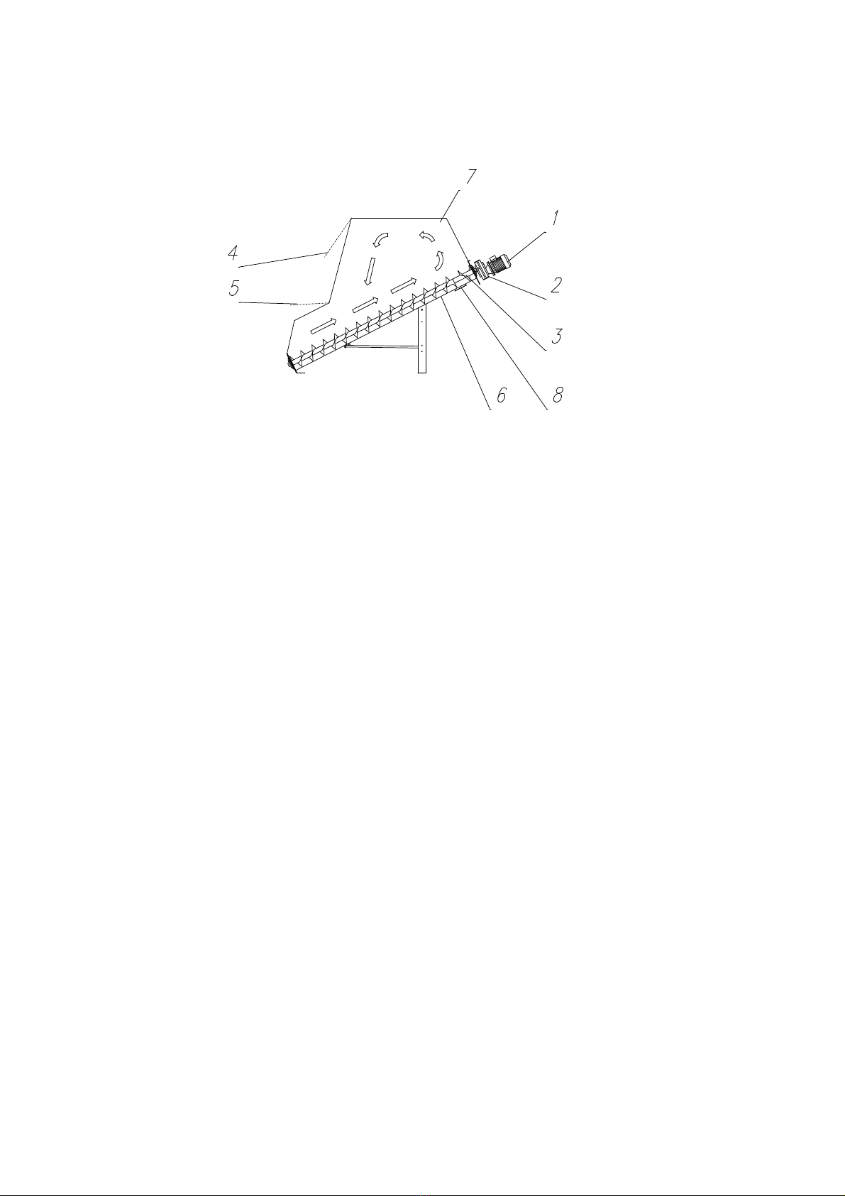
Fig. 1 Mixing principle
Pos. 1 Motor
Pos. 2 Gear
Pos. 3 Mixer auger
Pos. 4 Inspection/cleaning door
Pos. Inlet door
Pos. 6 Auger trough
Pos. 7 Superstructure
The mixer consists of an inclined auger trough, pos. 6, in which the mixer auger,
pos. 3, is placed. The mixer auger is driven by a shaft gear, pos. 2, on which the
motor, pos. 1, is mounted. The auger trough is mounted with a superstructure,
pos. 7, equipped with an inspection/cleaning door, pos. 4, and an inlet door for
filling, pos. .
The mixing is undertaken by a heavy, slowly running auger.
The components to be mixed can be added through the mixer top or lower filling
door. Material addition from a hammer mill is normally done through the mixer
cover via a cyclone. Concentrates are added by means of one or more augers
that can be connected in the mixer cover.
Addition of liquids, if any, is done after adding all dry components, and with the
mixer in operation.
Liquids are added at the top of the mixer through piping or hose lead some
distance down into the mixer.
Mixing the material:
The material is conveyed by a strong auger into the upper end of the mixer
where the mixer is designed in such a way that the material is pressed up like a
molehill and then glides back to the lower end of the auger. This gives a careful
and homogeneous mixing procedure.
- -
5.0 MOUNTING
5.1 Erection Tools
-Hand hammer
-Screwdrivers with straight and star slot
-Ring/fork wrench 8, 10, 13, 17 and 19 mm
-Various allen keys
-Tackle, min. allowed load 00 kg
-Ladder
5.2 Instructions for Erection
The mixer must be erected on an even, concreted floor with a bearing capacity of
min. 7 kg/cm².
At delivery the mixer hopper is assembled with the auger. The unit is transported
to the required place on the attached wheels.
5.3 Mounting of Motor and Gear
Motor and gear are supplied separately, and the motor is only mounted on the
gear when the unity shall be mounted on the auger.
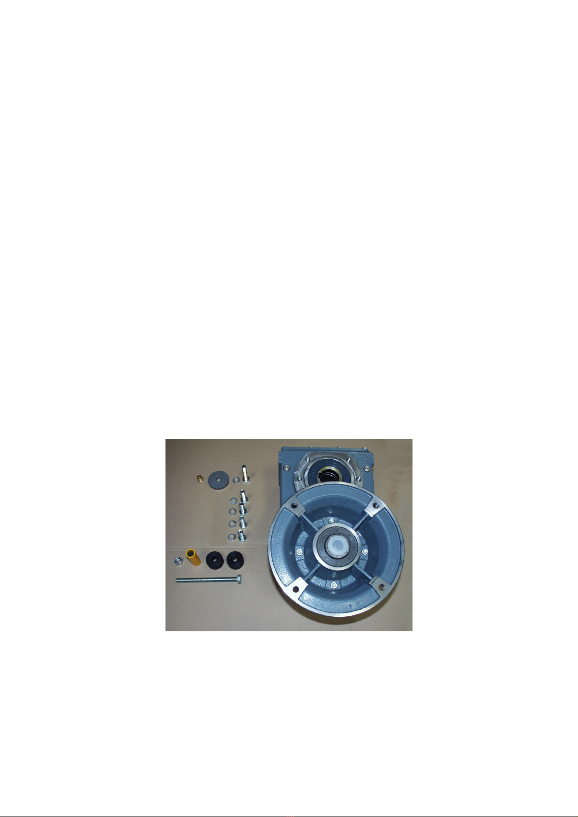
Check that the parts, figure 2, are supplied with gear and motor.
Fig. 2 Parts for gear
Place the gear on an even foundation with the motor flange upwards.
Then the motor is mounted on the gear. Be careful placing the key of the motor
shaft opposite to the groove of the inlet shaft of the gear.

- 6 -
Fig. 3 Mounting flange for motor
The motor is fastened with the enclosed 4 pcs. M12x30 bolts with belonging
discs.
Fig. 4 Mounting of motor on gear
- 7 -
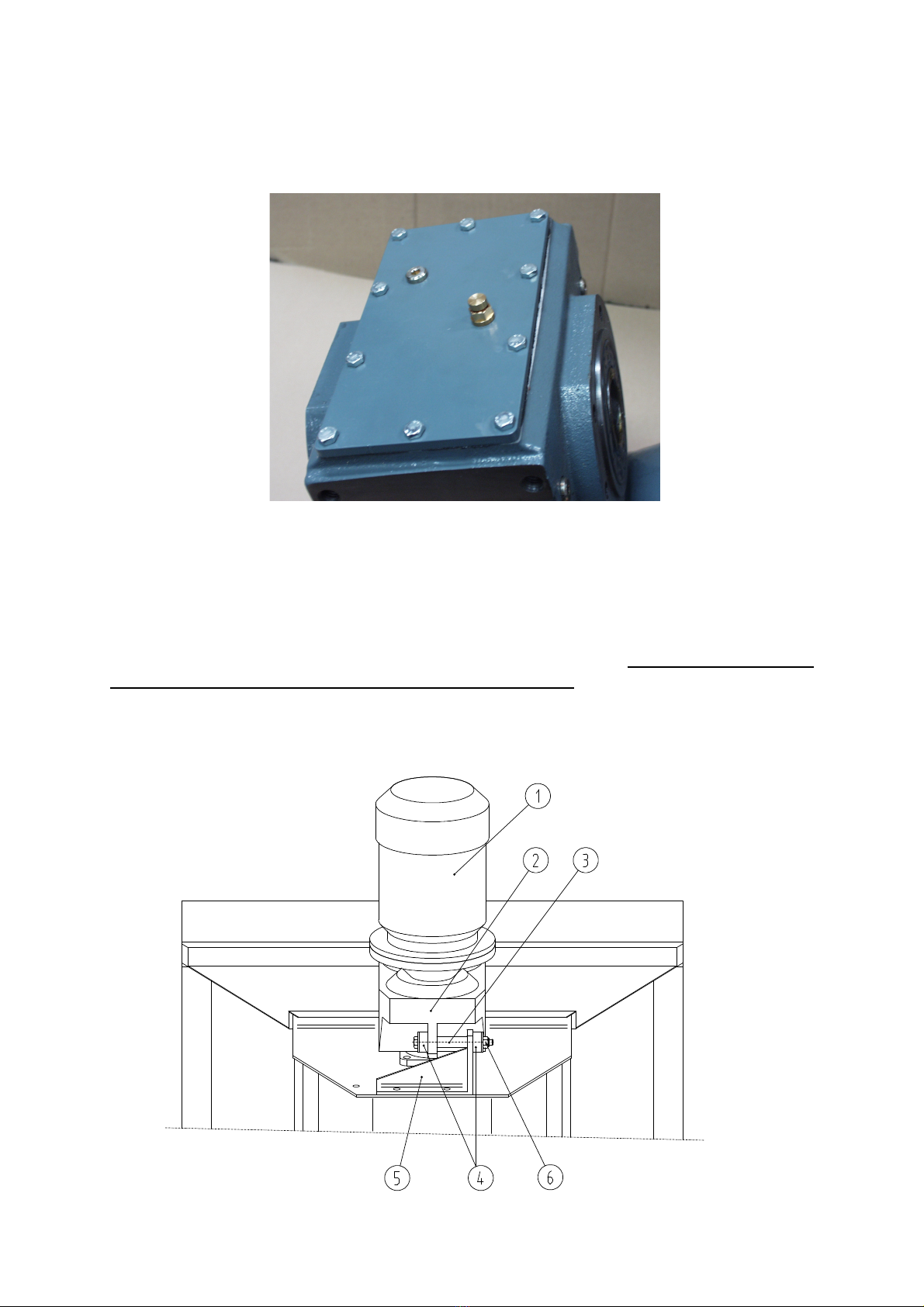
Remove the plug for oil filling at the top of the gear and replace it with an air-
escape valve.
Fig. 5 Air-escape valve for gear
Grease the hollow shaft of the gear in order to ease the mounting on the mixer
auger.
Mount the gear, figure 6 pos. 2, on the shaft of the mixer auger and secure it
with disc and bolt. Connect the gear to the instantaneous bracket, pos. , with
rubber bushings, pos. 4, and distance pipe, pos. 3. Secure the through-going bolt
with self-locking nut, pos. 6, that is only tightened a bit. (Remember! Check
the gear oil level before starting, see figure 14!)
Fig. 6 Mounting of instantaneous brac et

- 8 -
5.4 Erection of the Mixer
The auger trough is mounted with auger and hopper with safety grid when
supplied from the factory.
In order to secure that the mixer is tight attach the enclosed tightening tape to
all assembled surfaces before the mixer superstructure is mounted.
The pos. Nos. refer to figure 7.
Bolt the sides for the auger trough, pos. 10 and 11, and end plate, pos. 23, onto
the auger trough with M6x16 flange screws and belonging flange nuts.
Mount cover plates, pos. 27, on the two side plates, pos. 12 and 13, with M6x16
flange screws and nuts.
Bolt the sides for the superstructure, pos. 12 and 13, the back plate, pos. 16,
and the lower front plate for the superstructure, pos. 14, with M6x16 flange
screws and belonging flange nuts.
Bolt the plough, pos. 7, onto pos. 14 with M10x16 screws and belonging nuts and
discs.
Bolt cover for hopper, pos. 9, onto the lower front plate, pos. 14, with M6x16
flange screws and belonging flange nuts. Safety grate beneath the cover should
be mounted.
Connect the upper front plate for superstructure, pos. 1 , to the inspection
cover, pos. 22, with 3 hinges fixed with M6x16 flange screws with belonging
flange nuts.
Mount front plate and cover on the superstructure with M6x16 flange screws and
nuts. The cover is secured with hand wheel.
Mount the cover, if any.
Mount the holder for inspection cover in open position (eyebolt with wire), pos.
29, on the two corners of the superstructure.
Raise the mixer at the motor end, and mount the legs, pos. and 6, as well as
braces, pos. 30 and 31, with screws M12x30 and M8x20 with belonging nuts and
spring washers.
Mount the braces (across and inclined), pos. 24 and 2 , as distance piece
between the legs and between the legs and the auger trough with screws
M10x16 and belonging nuts and discs.

- 9 -
Fig. 7 Erection of the mixer
29 12 13 16
23
1110
27
7
9
2 24
14
22
1
6
30 31
5.5 Mounting of Emptying Auger
Fig. 8 Mounting of emptying auger
Pos. 1 Auger trough
Pos. 2 Q20 clamp
Pos. 3 Ø 102 mm single or double auger outlet
Single emptying auger can be mounted to the right or to the left.
- 10 -
5.6 Addition of Liquids
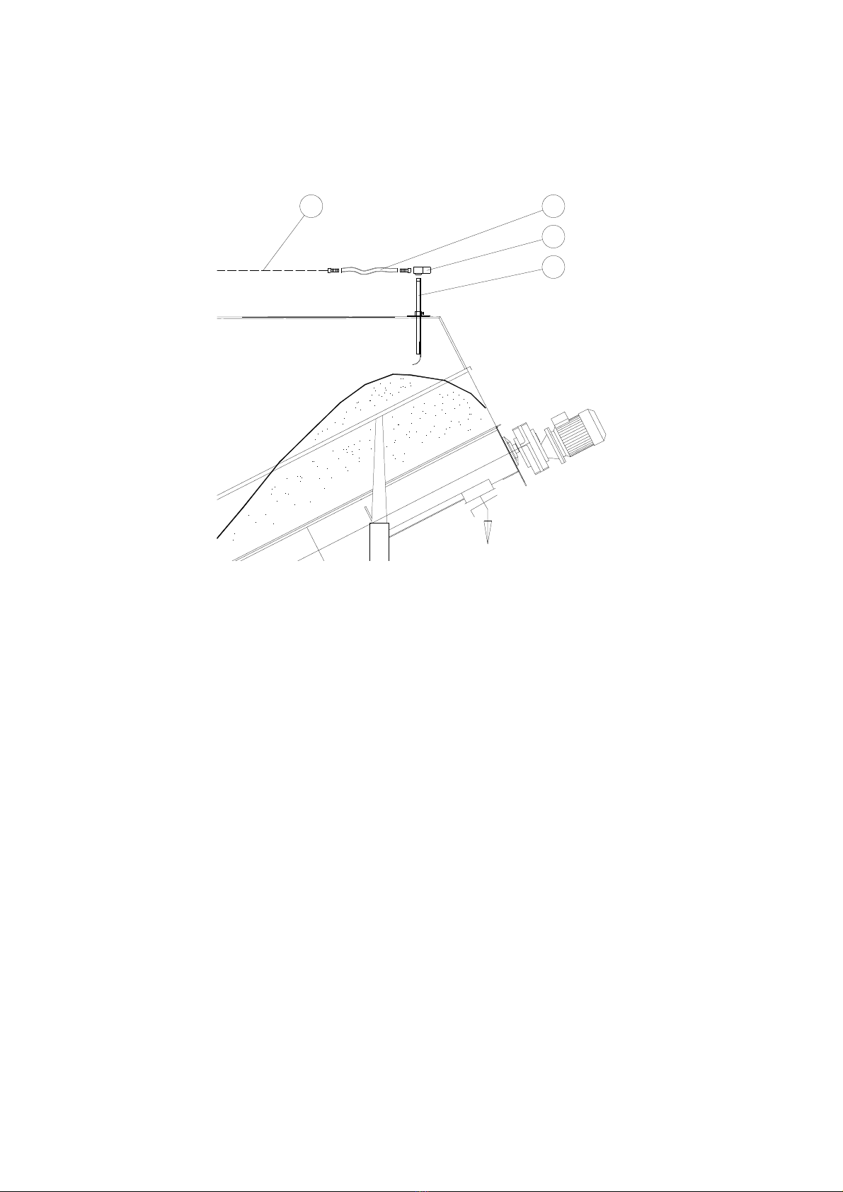
Fig. 9 Example of addition of liquids
2
3
4
1
Pos. 1 Piping for liquids from pump
Pos. 2 Flexible connection for weighing system
Pos. 3 Drip stop (excess-pressure valve, 1 bar)
Pos. 4 Inlet pipe, adjustable in the height
It is recommended to add the liquids approx. over the mixer outlet, as there is
always material here irrespective of the size of the batch.
The outlet of the liquids must be as close to the material surface as possible in
order to secure an effective mixing and minimize splashes inside the mixer.
- 11 -
5.7 Mounting of Ventilator
Fig. 10 Mounting of ventilator
Place filter and ventilator cornerwise in two separate corners of the cover as
shown in figure 10.
It is of no importance which side of the mixer is chosen.

- 12 -
5.8 Mounting of Load Cells
The load cells are normally supplied on foot.
DO NOT fasten the foot to the floor, as the load cells must be able to centre
themselves during loading.
If the load cells are fixed, faulty load may occur causing faulty weighing.
Mount a swivel pin with conical nut on each load cell.
Place the steering hole of the mixer foot over the conical nut as shown in figure
11.
Fig. 11 Mounting of load cell
1
2
3
4
Pos. 1 Mixer foot
Pos. 2 Steering pin
Pos. 3 Cone
Pos. 4 Load cell on foot
It is important that the weighing system is standing totally free without
unintended load on the load cells.
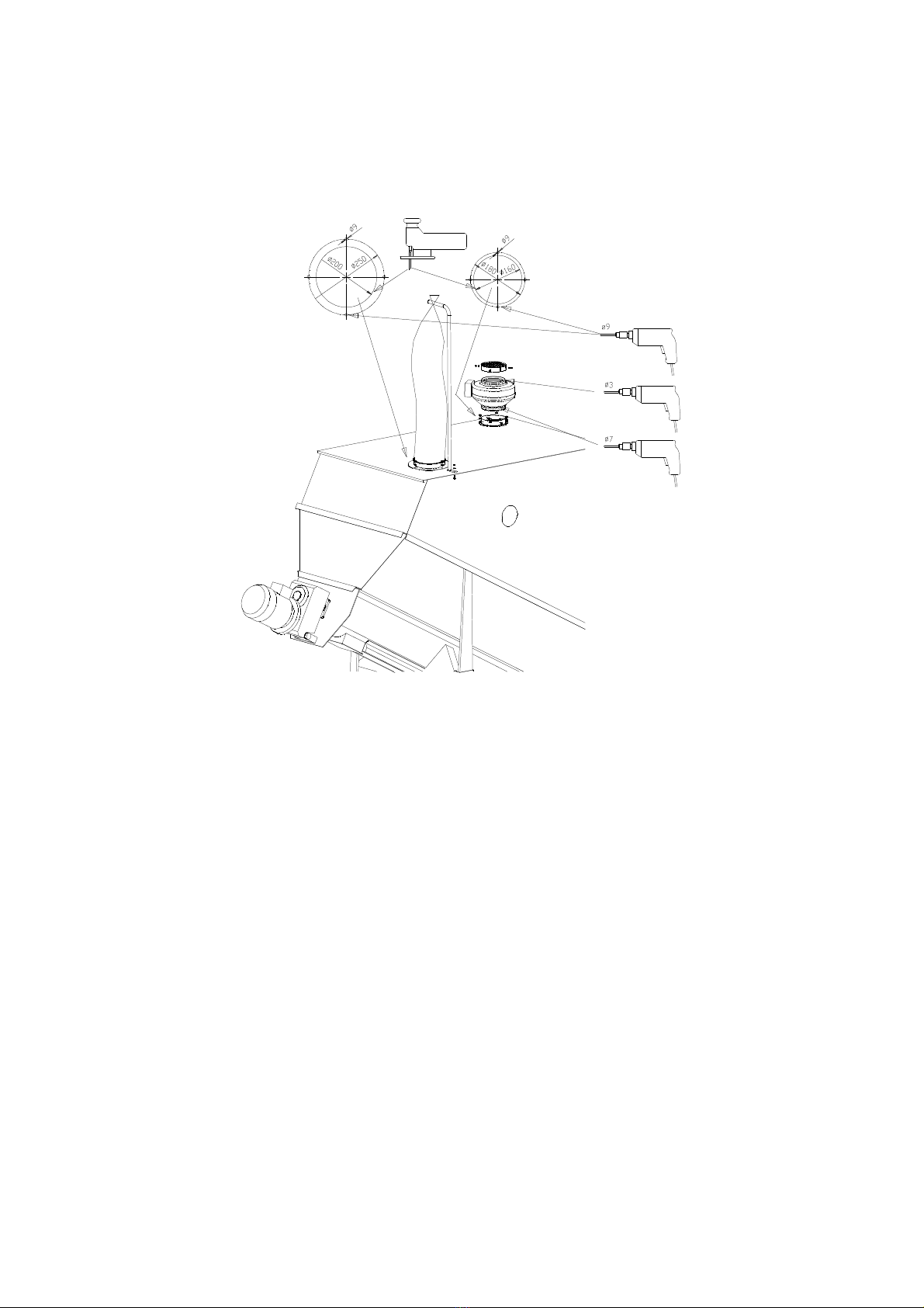
- 13 -
If you weigh into the mixer from auger, mill with cyclone or the like – and it is
the case of a closed system – you must use flexible connctions between the
transport system and the weighing system, figure 12 pos. 3.
Fig. 12 Connections to weighing system
Pos. 1 Suspension iron
Pos. 2 Cyclone/auger
Pos. 3 Flexible connection
Pos. 4 Mixer
Augers, cyclone etc. may not rest on the mixer.
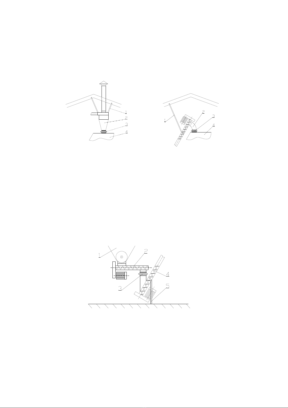
Also use flexible connection to emptying auger, if any, figure 13 pos. 3.
Fig. 13 Connection to emptying system
Pos. 1 Mixer
Pos. 2 Emptying auger
Pos. 3 Flexible connection
Pos. 4 Transport auger
Pos. Suspension iron
The transport auger may not rest on the weighing system.

- 14 -
6.0 STARTING THE MIXER
Check that there are no foreign bodies in the mixer before start-up.
Check that the direction of rotation is correct. The mixer auger shall take the
material towards the outlet.
If an emptying auger is removing the mixed material from the mixer, you adapt
the capacity adjusting the outlet throttle of the mixer.
The correct adjustment is found testing in praxis. Start with a small
opening/capacity and increase gradually.
Material may not pile up in the connection to the emptying auger.
7.0 OPERATION INSTRUCTION
7.1 Field of application
The mixer can be used within following fields:
-Mixing of minerals, granulated proteins and concentrate with ground grain –
sufficiently dry for storage or from moisture-proof silo with max. humidity of
2 %.
-Mixing with addition of up to max. 6% fat, oil or molasses, added continuously
during operation of the mixer.
Limitations:
-At grain from moisture-proof silo the mixer capacity can be limited to 800 kg
or less (depending on the humidity percentage of the grain).
-At mixtures with addition of molasses the capacity can be limited to 800 kg or
less (depending on the humidity percentage and quantity to be added).
-At mixtures with addition of CCM the capacity can be limited to 600 kg or less.
CCM may max. be 40% of the mixture, and the humidity of the CCM may max.
be 0%.
-At mixtures consisting of ground grain and whole peas and pellets there might
be a certain separation.
When deviating from above the producer must be consulted on beforehand and
accept the use of the mixer. If not, the guarantee lapses.

- 1 -
7.2 Operation
In order to obtain the best utilization of the mixer, the following should be
followed:
-Various components to be mixed can be added manually via the hopper or
automatic with an auger, fan, pump or the like.
-If the mixer is equipped with emptying auger, so that the outlet throttle is
always totally or partly open, a small portion will be left in the outlet and this
portion will not be mixed with the rest. It must be avoided that
concentrates/minerals gather here.
Therefore addition of this as first component must take place at the opposite
end of the mixer compared to the outlet, and the mixer auger may not be
started before part of the main component (such as ground barley/wheat) is
added. If not, the concentrates/minerals will be taken to the outlet.
As an alternative concentrates/minerals can be added after the main
components.
-When adding components in larger quantities it must be secured that the
material is distributed in the mixer so that the inlet is not blocked. The mixer
must be started now and then during the intake or alternatively started for a
while between addition of each component (minimum 1 minute).
-Liquids must always be added as last component and while the mixer is
operating.
In order to secure homogeneous mixing of concentrates/minerals it might be
an advantage to dry-mix 3- minutes before liquids are added.
The liquids must be sprayed over the dry components at a distance as short as
possible and in a position where there is always material irrespective of the
size of the portion – i.e. approximately over the mixer outlet.
Liquids may also be added manually via the hopper, but only if the mixer is full
so that the mixer auger is not visible at any point. Liquids must be added
slowly so that they can be absorbed by the dry matter.
-CCM is added in the following order:
1. Flour
2. Concentrate
3. CCM – while the mixer is operating.
The max. mixing capacity when adding CCM is 600 kg with max. 40% CCM
with max. 0% humidity.
-Start the mixer after accomplished filling.
-The mixing time is 10-1 minutes depending on the material and the size of
the portion. The mixing time is increased when adding liquids.

- 16 -
-After the mixing the mixer is emptied via outlet, emptying auger or fan
depending on the construction of the plant. During emptying the mixer must
be in operation in order to empty the mixer completely.
-NB: The emptying capacity must be adapted to the capacity of the transport
auger by adjusting the throttle in the mixer outlet.
8.0 MAINTENANCE
8.1 Mechanics
The bearings of the mixer auger are lifetime lubricated.
Check the oil level of the gear, fig. 14, every sixth month. The plug must be
unscrewed for check of the oil level.
Fig. 14 Oil level of the gear
Lubrication interval: Oil change every 20,000 operation hours.
Oil type: Mineral oil ISO VG 220 or similar type.
Quantity: 2. litres.
8.2 Cleaning
Note! All cleaning must take place in a way without forming dust clouds causing
danger of explosion. Consequently, compressed air cannot be recommended. Use
brush or vacuum cleaner instead.
In order to ensure necessary cooling and reduce the fire risk, motor and gear
may not be covered by dust. Cleaning must take place in a way not causing dust
clouds.
If ventilator is mounted in the mixer, the fan housing and wing may not be
covered by dust or the like.

- 17 -
Depending of the humidity of the grain, grinding method and quantity of liquids
added the mixer auger and inner surfaces may be covered by dirt. This may build
fertile soil for poisonous fungus and germs, so that the mixer must be regularly
cleaned inside.
If the mixer is mounted on load cells, they must be clean. If not, there is a risk of
faulty weighing. For the same reason it is necessary, regularly to remove dirt
from the mixer cover.
9.0 FAULT FINDING
Established fault, cause and repair
The mixer does not start
•Mechanical fault. Check motor/gear and auger connection.
•Foreign bodies in the mixer. Check the mixer.
The motor does not start
•Thermal contact released because of overload. Check that the adjustment is
correct.
•Fuse is burnt out. Replace the fuse. Call an electrician.
The mixer does not empty
•Attached emptying auger has not started. Start auger motor.
10.0 DISMOUNTING THE MIXER
Dismounting the mixer is carried out in the reverse order as mounting. When the
superstructure is taken down, the plates can ”stick” together because of the use
of tightening tape, and therefore it is recommended to wear working gloves
during the operation.
- 18 -
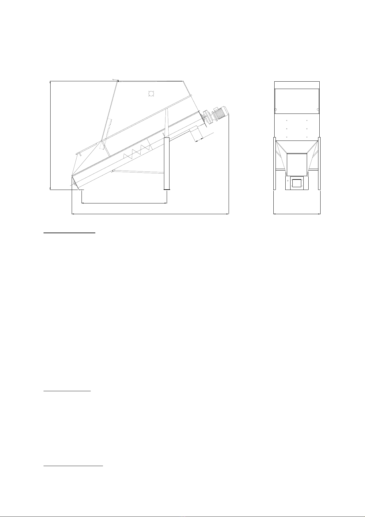
11.0 TECHNICAL SPECIFICATIONS
Fig. 15 Dimensional s etch
377 1130
2600
200
20 0
Technical data:
Mixer volume 2800 l
Mixer capacity:
- Dry feed max. 1000 kg
- Moist feed from moisture-proof silo max. 800 kg
- Dry feed with fat/oil max. 1000 kg
- Dry feed with molasses max. 800 kg
- Feed with max. 40% CCM, max. 600 kg (CCM max. 0% humidity)
Addition of fat, oil and molasses max. 6%
Mixing time 10-1 minutes
Emptying time -10 minutes
Inclination 27
o
Motor 1400 rpm, 4 kW
Transmission Gear i=34.91
Weight 440 kg
Mixing ability:
Tests from Bygholm (official Danish test institute) show following variation
coefficients when mixing 1000 kg consisting of ground barley mixed with 1% Ø 4
mm pellets and 1% salt, at 20 minutes mixing time:
1. Pellets = 9.7%
2. Salt = 8.2%
Shipping volume: 3.8 x 1.3 x 0.9 m

- 19 -
12.0 EX-ZONE SPECIFICATION
Fig. 16 Ex-zones
Zone 22
Zone 21
Ex-zones according to unified standards DS/EN 1127-1, DS/EN 0281-3, DS/EN
13463-1.
Around the mixer and in a distance of min. 1 m to the extreme point is zone 22.
Inside the mixer is zone 21.
In order to observe above zones the mixer must be equipped with cover, and the
inspection and filling doors must be closed while the mixer is in operation, or the
mixer is filled by the mechanical feeding system.
If the mixer is placed near other equipment with a zone stated to have bigger
danger of explosion, and so that the zones are overlapping each other, the most
important zone statement is valid in the overlapped area.

- 20 -
13.0 ACCESSORIES
Cover 90021
Inlet connection Ø 1 0 200010G
Inlet connection Ø 1 0, 60° 90026
Flexible connection Ø 1 0 1920399
Ventilator with filter 90024
Emptying auger, Ø 102 single, 1.1 kW 280 rpm 90093
Emptying auger, Ø 102 single, 1.1 kW 60 rpm 90094
Emptying auger, Ø 102 double, 1.1 kW 280 rpm 9009
Emptying auger, Ø 102 double, 1.1 kW 60 rpm 90096
Emptying auger, Ø 1 2 single, 1. kW 280 rpm 90099
Load cell on foot (3) 1400684
Fat addition kit 90102
Table of contents


