Equustek DL6000 User manual

DL6000
User Manual
Revision 1.01 – June 12, 2007

#286-5489 Byrne Rd., Burnaby, BC, V5J3J1, Canada Phone: 888-387-3787 or 604-266-8547 www.equustek.com
2
Contents
1 GENERAL OPERATION AND APPLICATIONS...................................4
2HARDWARE SPECIFICATIONS AND LAYOUT..................................5
2.1 OPERATING SPECIFICATIONS................................................................................. 5
2.2 PHYSICAL SPECIFICATIONS ................................................................................... 6
2.3 HARDWARE LAYOUT ............................................................................................ 6
3MODE OF OPERATION.............................................................................7
3.1 ONLINE MODE OF OPERATION .............................................................................. 7
3.2 OFFLINE MODE..................................................................................................... 7
3.2.1 BIOS Manager Options...................................................................................7
4SWITCH AND LED INDICATOR FUNCTIONS ....................................9
4.1 SWITCH FUNCTIONS.............................................................................................. 9
4.2 INDICATOR FUNCTIONS......................................................................................... 9
4.2.1 Power-Up and Reset Sequence .......................................................................9
4.2.2 Normal On-line Operation............................................................................10
4.2.3 On-Line, Power-Up and Reset Errors...........................................................11
4.2.4 Off-Line Modes..............................................................................................11
5CONFIGURATION....................................................................................12
5.1 DEVICE INSTALLER............................................................................................. 12
5.1.1 IP Address.....................................................................................................12
5.1.1.1 Device Not Found....................................................................................15
5.1.2 Telnet.............................................................................................................16
5.1.3 Modbus TCP Telnet Settings.........................................................................18
5.1.3.1 Modbus Slave Settings.............................................................................18
5.1.3.1 Modbus Master Settings..........................................................................19
5.3 EQ32 CONFIGURATION SOFTWARE .................................................................... 20
5.3.1 Configuring Modbus Parameters..................................................................20
5.3.1.1 Modbus Slave Parameters.......................................................................22
5.3.1.2 Modbus Master Parameters ....................................................................25
5.3.2 Configuring Modbus Parameters using the DL Offline Manager.................26
5.4 ALLAN-BRADLEY NETWORK CONFIGURATION................................................... 29
5.4.1 DH+ Node Address.......................................................................................29

#286-5489 Byrne Rd., Burnaby, BC, V5J3J1, Canada Phone: 888-387-3787 or 604-266-8547 www.equustek.com
3
5.4.2 DH+ Baud Rate.............................................................................................29
5.4.3 DH-485 Node Address ..................................................................................30
5.4.4 DH-485 Baud Rate........................................................................................30
6FIRMWARE UPGRADE...........................................................................31
6.1 EQ32 CONFIGURATION SOFTWARE .................................................................... 31
7WIRING DIAGRAMS................................................................................34
7.1 DL6000 PINOUT DIAGRAM................................................................................. 34
7.2 RS-232 NULL MODEM CABLE............................................................................ 35
7.3 DH+ CABLE........................................................................................................ 35
7.4 DH-485 CABLE................................................................................................... 35
8DL6000 TYPICAL APPLICATIONS.......................................................36
8.1 DL6000-MEDH+............................................................................................... 36
9FREQUENTLY ENCOUNTERED PROBLEMS ...................................37
9.1 DEVICE INSTALLER CANNOT FIND THE DL6000.................................................. 37
9.2 CANNOT COMMUNICATE TO DH+ NODE 0USING THE DL6000-MEDH+............ 38
APPENDIX A: TCP/IP TUTORIAL..........................................................39
A.1 IP ADDRESS ........................................................................................................ 39
A.2 SUBNET MASK.................................................................................................... 40
A.3 IP ADDRESS AND SUBNET MASK COUPLE........................................................... 40
A.4 VALID IP ADDRESSES ......................................................................................... 41

#286-5489 Byrne Rd., Burnaby, BC, V5J3J1, Canada Phone: 888-387-3787 or 604-266-8547 www.equustek.com
4
1 General Operation and Applications
The DL6000 hardware platform was designed to be a gateway which interfaces your
Ethernet Modbus TCP Networks to AB’s Data Highway Plus (DH+), or DH-485
networks. Thus extending the life of existing Allen-Bradley PLC’s and SLC’s without
Ethernet Interfaces. It comes in a DC powered Din-Rail Mountable compact cabinet for
ease of portability and installation. The DL6000 combines the Lantronix
XPORT_MBTCP Ethernet Microprocessor with our proven A-B interface.
The DL6000 comes with a RJ-45 Connector for the 10/100 Base-T Ethernet link, and a 3
pin Phoenix plug for connection to A-B networks. Power is supplied via a 3 pin Phoenix
type plug which allows for 9-27 Volts DC to be connected. Included is a RS232 DB9
and a USB Configuration Ports for access to the BIOS and Flash Burn Utilities.
Configuration of the operating parameters is done quickly and easily via the Ethernet
Link by Telnet or the supplied Lantronix Device Installer software. Current releases of
the software can be obtained from Lantronix’s Website.
Modbus TCP communication is handled by any generic Modbus TCP driver, tested ones
include Citect, Parijat, and Kepware.

#286-5489 Byrne Rd., Burnaby, BC, V5J3J1, Canada Phone: 888-387-3787 or 604-266-8547 www.equustek.com
5
2 Hardware Specifications and Layout
The DL6000 Hardware Platform has the following specifications.
2.1 Operating Specifications
Our DH+ versions A-B Channel allows Synchronous Transformer Coupled SDLC
connection to Allen Bradley DH+. Speeds of 57.6K, 115.2K and 230.4K Baud are
available.
Our DH-485 versions A-B Channel allows for Isolated DH-485 (RS485) connection to
Allen Bradley DH-485 network. Speeds of 4800, 9600 and 19.2K (default) Baud are
available.
Ethernet Channel allows 10/100 Base-T connections to TCP/IP and other Ethernet
networks.
Currently Modbus TCP makes use of our proven Modbus to AB network interoperability.
Simple Parameter Configuration using menu driven Windows based Programs via
Ethernet 10/100 Base-T.
Configuration and Reset Pushbuttons go into BIOS features and Flash Setup and do a full
Hardware Reset.
Operating Parameters are stored in Non-Volatile Serial EEPROM.
The DL6000 uses FLASH upgradeable firmware from either the supplied EQ32
configuration program or once can use a HyperTerminal type program set to 19200,N,8,1
and XON/XOFF flow control.
Bi-Color (Green/Red) LED’s for Ethernet and A-B Channels indicates activity and status.
Green POWER LED indicates power on.
Bi-Color LED’s for Ethernet Link and Tunneling Status, Diagnostic.

#286-5489 Byrne Rd., Burnaby, BC, V5J3J1, Canada Phone: 888-387-3787 or 604-266-8547 www.equustek.com
6
2.2 Physical Specifications
Dimensions: 1.2" H x 4.75" D x 3.2" W (30.4 x 120.7 x 81.3 mm) - Weight 0.56 Lbs (0.2 Kg)
Installation: Metal Enclosure; Desktop, # 8 Bolts, or Din Rail Mounting
Operating Environment: 32 to 122 °F (0 to 50 °C)
Storage: -40 to 185°F (-40 to 85°C)
Humidity: 5% to 95% non-condensing
Power: 9-27V DC – 3.0 Watts
2.3 Hardware Layout
This Section contains information of the physical position and purpose of the components of the
DL6000.
The top row contains the following connectors. Going left to right.
3 pin Power Connector
A-B Network 3 pin Screw terminal (Phoenix Type)
The LED’s on the left side going from top to bottom.
CHA A-B Network Status
CHB Ethernet Activity (TX/RX).
CHC DL6000 Operating Mode and Status.
The LED’s on the RJ45 on the side.
Ethernet Activity (Port TX/RX) On the right side of the RJ45
10/100 Base-T Ethernet Link Status On the left side of the RJ45
The RESET pushbutton is on the left side, the Configure pushbutton is on the right side.
The bottom side of the DL6000 has the following connectors: Going Left to Right.
9 Pin DB9 connector for MODBUS Configuration, the BIOS and Firmware.
USB connector for MODBUS Configuration, the BIOS and Firmware
RJ-45 connector for 10/100 Base-T Ethernet communications

#286-5489 Byrne Rd., Burnaby, BC, V5J3J1, Canada Phone: 888-387-3787 or 604-266-8547 www.equustek.com
7
3 Mode of Operation
3.1 Online Mode of Operation
Online Mode is the normal operating Mode of the DL6000. In this mode the Channels
are now configured as they are defined by the A-B Network and Configuration. The
DL6000 is ready to interface your equipment.
The Reset pushbutton automatically puts the DL6000 into Online mode.
3.2 Offline Mode
Once the Configure Pushbutton is Pressed the Offline BIOS Manager is started. Using
either the EQ32 configuration software and the “DL Offline Manager” option or a
Windows Hyper Terminal type program with com port settings of 19200 Baud, 8,N,1 and
Xon/Xoff flow control.
BIOS MANAGER for DL6000-1.00- Jun 16,06
(c) Equustek Solutions Inc. 2006
MAIN MENU
1 - Restore EEPROM
2 - WRITE new Firmware
3 - Memory DUMP
4 - OFF-LINE Diagnostics
5 - DEBUG Mode
6 - FIRMWARE Version
7 – ONLINE
8 - CONFIGURE Model Parameters
MAKE SELECTION (1-8) -
3.2.1 BIOS Manager Options
Restore EEPROM to factory settings
Once pressed you will be asked “Restore EEPROM to defaults (Y/N)?” If the answer
is “Y”es then the Online parameters will be reset to defaults of Address 1, and
settings of 9600,N,8,1 on the communication Channel to the COBOX.
Write New Firmware
Once pressed the message “This *WILL* overwrite DATALINK system code enter
(Y/N) to proceed” will be displayed. Hit “Y” and the next message will appear
telling you that it is alright to send the new firmware to the Flash;

#286-5489 Byrne Rd., Burnaby, BC, V5J3J1, Canada Phone: 888-387-3787 or 604-266-8547 www.equustek.com
8
ERASING FLASH, PLEASE WAIT...
SEND FIRMWARE TEXT FILE NOW...
Once the message to send the firmware appears then either click on the “Burn Flash
System File” button to select the .txt file to send, or send the Text File under
HyperTerminal.
Wait for an “*A-OK* BURN COMPLETE!” message to appear.
Memory Dump
This is used to display the RAM memory of the DL6000. This should only be done
after contacting Equustek Solutions to debug problems.
Off-Line Diagnostics
Starts a series of tests to test the DL6000’s hardware and should only be done if
instructed so by a trained person.
Debug Mode
Starts up a DL6000 internal Debug mode that can be used by trained personnel to
debug problems and check hardware configuration and operation.
Firmware Version
Once selected the current DL6000 model and version numbers will be displayed. Can
be used to check the correct firmware was burnt into the Flash or if the DL6000 has
the most up to date firmware in the Flash.
Online
Does a soft “software” reset of the unit to put it online. This will NOT reset the
COBOX (Ethernet) hardware.

#286-5489 Byrne Rd., Burnaby, BC, V5J3J1, Canada Phone: 888-387-3787 or 604-266-8547 www.equustek.com
9
4 Switch and LED Indicator Functions
4.1 Switch Functions
Reset Pushbutton
The Reset pushbutton will perform a complete hardware reset of the DL6000. It is
identical to a complete power cycle and will cause the DL6000 to go through its LED
start-up sequence as defined in Section 5.2.1. A complete hardware reset is needed on
changing any online operating parameters.
Configure Pushbutton
The Configure pushbutton takes the DL6000 out of On-Line operation mode and puts it
in the BIOS Manager mode. When this mode has been entered, CHA and CHC LEDs
will be RED and CHB LED will be GREEN. To put the unit back On-line it is necessary
to either press the Reset or cycle the DC power supplied to the DL6000.
4.2 Indicator Functions
4.2.1 Power-Up and Reset Sequence
On Power-up or after the Reset button has been pressed the DL6000 executes a self
diagnostic check-up or the ram and flash firmware. The correct LED indicator sequence
to show the DL6000 is functioning properly is as follows: After all LEDS go out.
LED Status
Power Green Continuously
CHC LED (Status) Green for 0.5 seconds
CHB LED (Ethernet) Green for 0.5 seconds
CHA LED (A-B Network) Green for 5 seconds
CHA LED Green for
An other 8 seconds
CHB LED Red for
After this sequence the DL6000 goes into the On-line mode of Operation. The LED
indicators will behave in the certain way defined by the DL6000 model used. Most likely
the A-B Network will be solid or flashing depending on the A-B Network used.

#286-5489 Byrne Rd., Burnaby, BC, V5J3J1, Canada Phone: 888-387-3787 or 604-266-8547 www.equustek.com
10
4.2.2 Normal On-line Operation
The following is a description of the normal operation of the LED’s on the DL6000.
LEFT LED’s Description of Operation
Power Green Indicates Power is being supplied to the DL6000.
(Ethernet) Flashes GREEN for 0.5 seconds when a character is Received or
Transmitted. If Characters are being received of transmitted faster
than this then it might appear the LED is on SOLID. Flashes RED
for 0.5 seconds if a NAK is received or transmitted. Will also
flash if all serial communication buffers are full.
A-B Network (DH+ )
On Hardware Reset will flash GREEN and RED until a valid DH+
network is detected. This is the AUTO BAUD Rate detection
mode, the DL6000 will automatically connect at the DH+ speeds
of 57.6K, 115.2K and 230.4K Baud. LED will switch to on solid
once the DL6000 is on the DH+ network as a valid node address.
LED will flash GREEN when the DH+ is set to a certain Baud rate
but is not on network.
(DH-485)
On Hardware reset the A-B Network will flash GREEN at a 1
second rate when the DH-485 is not on network. Once a valid
network is running the LED will flash GREEN much more rapidly
(approx. every 0.1 seconds), the rate depends on how busy the
network is.
Status Used for Determining Operating Mode and DL6000 Status
RJ45 LED’s Description of Operation
Activity LED Blinks (amber 10BaseT) or (green 100BaseT) to
indicate an Ethernet socket has been established and
active.
Link LED Lights Solid Amber or Green to indicate Ethernet
Port is connected to the 10/100Base-T network.

#286-5489 Byrne Rd., Burnaby, BC, V5J3J1, Canada Phone: 888-387-3787 or 604-266-8547 www.equustek.com
11
4.2.3 On-Line, Power-Up and Reset Errors
The following table describes the meaning of LED patterns if the internal diagnostic tests
detect an error on Reset/Power-Up.
LED Pattern Description of Problem
Ethernet, A-B Network,
and Status Flashing
RED
Ethernet, A-B Network,
and Status Solid RED
Start-up Sequence keeps
repeating
A-B Network
Flashing RED
The flash has not be burnt properly and the A-OK was
not transmitted. Please reburn the flash with the correct
text file. Contact Customer Support for help.
The BIOS has been corrupted. A new Flash Chip has to
be supplied by the factory. Please contact Customer
support.
The DL6000 EEPROM is corrupt.. Please Restore to
Factory Settings (See Section 4.3) and then reconfigure
the unit.
There is a duplicate node on the A-B network. The
DL6000 has been assigned a node address that is already
in use.
4.2.4 Off-Line Modes
The following table describes the meaning of LED patterns in the different Off-Line
modes of operation.
LED Pattern Description of Operation
CHA and CHC Solid
RED
CHA, CHB and CHC
Solid Green
BIOS MANAGER
Offline Hardware Diagnostics Testing Mode
OR Offline Debug Mode
5 Configuration
The following sections describe how to setup and configure your DL6000 for the desired
online operating parameters. To configure your DL6000, the following software will be
needed.
Configuration Software
Device Installer - Used to assign IP address and update Lantronix
daughter board firmware.
ComPort Redirector - Creates a virtual COM port and redirects it to the PC’s
Ethernet port.
EQ32 Configuration - Used to map Modicon registers/coils to Allan-Bradley
data files with the DL6000-MEDH+ or MEDH-485.
After the IP address of the DL6000 is assigned, you must then telnet to the DL6000 to
setup the internal communications between the Lantronix daughter board and the
DL6000 motherboard. These settings are reset every time an IP address is assigned.
5.1 Device Installer
The Device Installer is used to configure the IP address of the DL6000 as well as
configure the internal communication settings between the Lantronix XPORT and the
DL6000 mother board. The most recent version of Device Installer is Device Installer
4.1.
5.1.1 IP Address
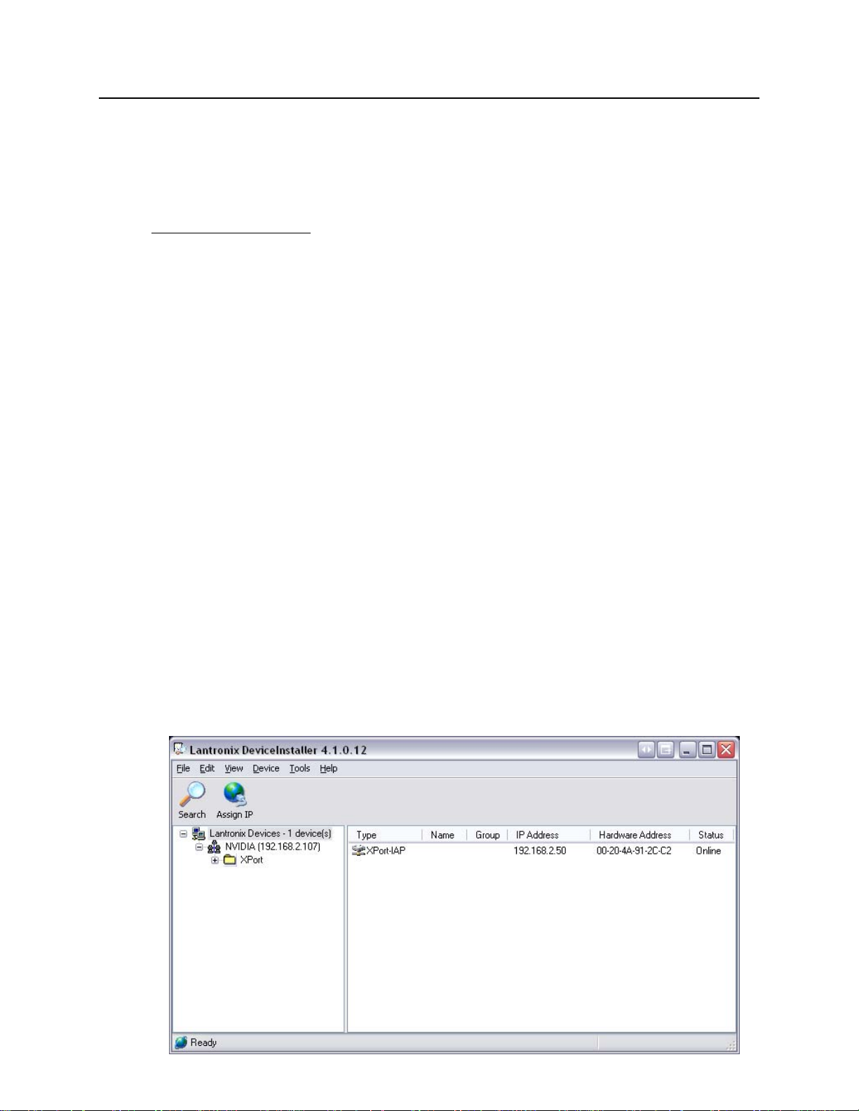
To assign an IP address to the DL6000, open the Device Installer Software. You will see
a screen as shown below.
#286-5489 Byrne Rd., Burnaby, BC, V5J3J1, Canada Phone: 888-387-3787 or 604-266-8547 www.equustek.com
13
The following steps are used to assign an IP address to the DL6000.
1. Click on the Search button to have the Device Installer find the DL6000. If the
Device Installer finds the DL6000, the device should appear. If the device cannot be
found then follow the instructions at the end of the IP Address section.
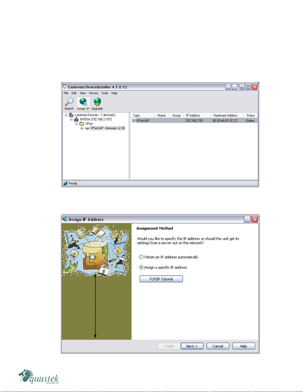
2. Highlight the device and click on the Assign IP button. Choose the “Assign a specific
IP address” option and click Next. The following window will appear.

#286-5489 Byrne Rd., Burnaby, BC, V5J3J1, Canada Phone: 888-387-3787 or 604-266-8547 www.equustek.com
14
3. Enter the desired IP address, subnet mask, and default gateway (if required) and click
Next.
4. To assign the chosen IP address to the DL6000, click the Assign button.
#286-5489 Byrne Rd., Burnaby, BC, V5J3J1, Canada Phone: 888-387-3787 or 604-266-8547 www.equustek.com
15
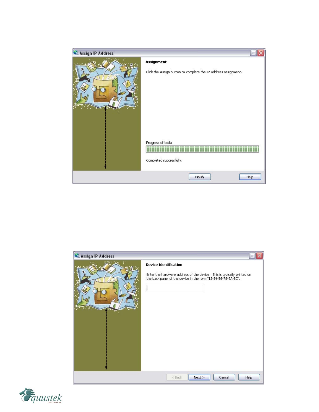
5. When the IP address is assigned, a message stating that the IP address was
successfully assigned should appear. Click the Finish button to close the screen and
go back to the main menu.
5.1.1.1 Device Not Found
If for some reason the Device Installer cannot find the DL6000 on the Ethernet network,
follow the steps below.
1. Click the Assign IP button and the following screen will appear.

#286-5489 Byrne Rd., Burnaby, BC, V5J3J1, Canada Phone: 888-387-3787 or 604-266-8547 www.equustek.com
16
2. Enter MAC address of the DL6000 and click Next. The MAC Address can be found
on the bottom of the DL6000. The Device Installer should now find the device. Now
follow the steps at the beginning of the IP Address section to assign an IP address. If
for some reason the device still cannot be found, see section 9.1 Device Installer
Cannot Find the DL6000.
5.1.2 Telnet
After the IP address of the DL6000 is assigned, the internal communication parameters
that the Lantronix XPORT uses to communicate with the DL6000 motherboard must be
configured.
To start a telnet session, there are two ways that can be used. The first method uses the
Device Installer while the second uses a DOS command prompt.
Telnet using Device Installer
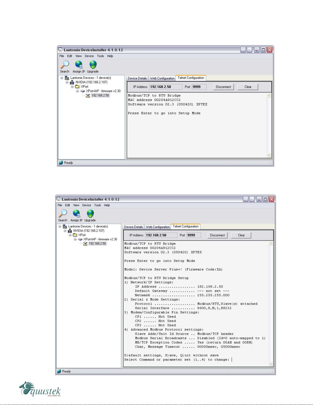
Open Device Installer and click search to find the DL6000. Once the Device Installer has
found the DL6000, double click on the device to bring up more options. Select the Telnet
Configuration tab as shown below.
.
#286-5489 Byrne Rd., Burnaby, BC, V5J3J1, Canada Phone: 888-387-3787 or 604-266-8547 www.equustek.com
17
Press the Connect button and when prompted, press the Enter key with in 5 seconds to
bring up the main menu.
After pressing Enter, you will get the following menu.

#286-5489 Byrne Rd., Burnaby, BC, V5J3J1, Canada Phone: 888-387-3787 or 604-266-8547 www.equustek.com
18
Telnet using the DOS Command Prompt
Open a DOS command prompt window to begin. At the prompt, type telnet then a space,
the IP address of the unit then a space, and then the port 9999. After this is entered, press
Enter to begin a telnet session. The following is an example of how to begin a telnet
session from the command prompt.
C:\>telnet 192.168.2.2 9999
Below are the Telnet settings for the different DL6000 models. After starting a telnet
session, you must press the Enter key with in 5 seconds to bring up the main menu.
5.1.3 Modbus TCP Telnet Settings
The following menu will appear after starting a telnet session.
Modbus/TCP to RTU Bridge Setup
1) Network/IP Settings:
IP Address ................. 192.168.2.50
Default Gateway ............ --- not set ---
Netmask .................... 255.255.255.000
2) Serial & Mode Settings:
Protocol ................... Modbus/RTU,Slave(s) attached
Serial Interface ........... 9600,8,N,1,RS232,DB25
3) Modem Control Settings:
DCD Output ................. Fixed High/Active
CTS Output ................. Fixed High/Active
4) Advanced Modbus Protocol settings:
Slave Addr/Unit Id Source .. Modbus/TCP header
Modbus Serial Broadcasts ... Disabled (Id=0 auto-mapped to 1)
MB/TCP Exception Codes ..... Yes (return 00AH and 00BH)
Char, Message Timeout ...... 00050msec, 05000msec
D)efault settings, S)ave, Q)uit without save
Select Command or parameter set (1..4) to change:
The telnet setup is slightly different depending on whether the DL6000 is to be
configured as a Modbus Slave or a Modbus Master. Follow the steps below for the
configuration you wish to use.
5.1.3.1 Modbus Slave Settings
To set the proper Telnet settings, follow the steps below:
1. Press D to restore Factory Defaults.
2. Press 2 to configure the Serial and Mode Settings. Input the values so that they match
what is shown below. The values shown in the parentheses are the current settings.
To keep the current settings, press Enter. The only value that needs to be changed is
the baud rate.
Attached Device (1=Slave 2=Master) (1)
Serial Protocol (1=Modbus/RTU 2=Modbus/ASCII) (1)
Interface Type (1=RS232 2=RS422/RS485+4-wire 3=RS485+2-wire) (1)
Enter serial parameters (9600,8,N,1) 115200,8,n,1

#286-5489 Byrne Rd., Burnaby, BC, V5J3J1, Canada Phone: 888-387-3787 or 604-266-8547 www.equustek.com
19
The main menu should now show “Modbus/RTU Slave(s) attached” for the Protocol
and “115200, 8, N, 1, RS232, DB25” for the Serial Interface under Serial and Mode
Settings. If your network is DH485 then your baud rate should be 19200 instead
of 115200.
3. Press S to save the new settings and end the telnet session.
4. Press the reset button on the DL6000 to put it online.
5.1.3.1 Modbus Master Settings
To set the proper Telnet settings, follow the steps below:
1. Press D to restore Factory Defaults.
2. Press 2 to configure the Serial and Mode Settings. Input the values so that they match
what is shown below. The values shown in the parentheses are the current settings.
To keep the current settings, press Enter.
Attached Device (1=Slave 2=Master) (1) 2
Serial Protocol (1=Modbus/RTU 2=Modbus/ASCII) (1)
Interface Type (1=RS232 2=RS422/RS485+4-wire 3=RS485+2-wire) (1)
Enter serial parameters (9600,8,N,1) 115200,8,n,1
The main menu should now show “Modbus/RTU Master attached” for the Protocol
and “115200, 8, N, 1, RS232, DB25” for the Serial Interface under Serial and Mode
Settings. If your network is DH485 then your baud rate should be 19200 instead
of 115200.
After setting the Serial and Mode Settings and returning to the main menu you will
see a 5th option, Unit ID -> IP Address Table, as shown below.
Modbus/TCP to RTU Bridge Setup
1) Network/IP Settings:
IP Address ................. 192.168.2.50
Default Gateway ............ --- not set ---
Netmask .................... 255.255.255.000
2) Serial & Mode Settings:
Protocol ................... Modbus/RTU,Master attached
Serial Interface ........... 115200,8,N,1,RS232
3) Modem/Configurable Pin Settings:
CP1 ...... Not Used
CP2 ...... Not Used
CP3 ...... Not Used
4) Advanced Modbus Protocol settings:
MB/TCP Exception Codes ..... Yes (return 00AH and 00BH)
Char, Message Timeout ...... 00050msec, 05000msec
5) Unit ID -> IP Address Table:
Close Idle Sockets ......... 10sec
Redundant Entry Retry ...... Feature Disabled
3. Press 5 to configure the Unit ID to IP Address mapping table. Here you will also
configure the time to wait before closing an idle socket.

#286-5489 Byrne Rd., Burnaby, BC, V5J3J1, Canada Phone: 888-387-3787 or 604-266-8547 www.equustek.com
20
4. After pressing 5, choose the timeout period for idle TCP sockets. The default is 10
seconds.
Close Idle TCP sockets after (3-60 sec, 0=leave open) (10)
5. Leave the Redundant entry retries option disabled. This is the default setting.
Redundant entry retries after (15-60 sec, 0=disable feature) (0)
6. The last part is to setup the Unit ID to IP Address mapping table. To add a table
entry, press A. You will now enter the range of unit ID’s to map to an IP address. To
map only one Unit ID to an IP Address, use the same Unit ID for both the beginning
and ending values. After selecting the Unit ID range, enter the IP Address of the
device to send the messages to. When finished, press Eto exit back to the main
menu. You can enter up to a maximum of 8 separate table entries.
7. From the main menu, press S to save the new settings and end the telnet session.
8. Press the reset button on the DL6000 to put it online.
5.3 EQ32 Configuration Software
The EQ32 software is required when configuring a DL6000-MEDH+ or a DL6000-
MEDH-485. The EQ32 software is used to setup the address mapping between Modbus
and Allan-Bradley networks.
5.3.1 Configuring Modbus Parameters
To configure your DL6000, open the EQ32 Configuration Software and follow the steps
shown below. The following welcome screen will appear when the software is opened.
Table of contents
Other Equustek Gateway manuals

Popular Gateway manuals by other brands


Cisco
Cisco UPWL6028F user guide

RTA
RTA 460ETC-NNA1 Product user guide

D-Link
D-Link DRO-210i user guide

ZyXEL Communications
ZyXEL Communications UAG Series reference guide

SonicWALL
SonicWALL TZ 150 Wireless Getting started guide

Pakedge Device & Software
Pakedge Device & Software RSB-KIT installation manual