CTS VRGIII-31412SFP-N User manual

1
VRGIII-31412SFP-N
4 ports 10/100/1000Mbps RJ-45; 2 ports VoIP FXS, built-in IEEE802.11n WiFi and 1 port 1000Mbps
SFP slot uplink VoIP Residential Gateway
VRGIII-31412SFP-N-DR
4 ports 10/100/1000Mbps RJ-45; 2 ports VoIP FXS, built-in IEEE802.11n WiFi and 1 port
100/1000Mbps SFP slot uplink VoIP Residential Gateway
VRGIII-31412-N-DR
4 ports 10/100/1000Mbps RJ-45; 2 ports VoIP FXS, built-in IEEE802.11n WiFi and 1 port
100/1000Mbps fiber optics uplink VoIP Residential Gateway
VRGIII-31412-CW-N-DR
4 ports 10/100/1000Mbps RJ-45; 2 ports VoIP FXS, built-in IEEE802.11n WiFi and 1 uplink port
combo (10/100/1000Mbps RJ-45 and 100/1000Mbps SFP slot) VoIP Residential Gateway
VRGIII-31412-N-DR-RF
4 ports 10/100/1000Mbps RJ-45; 2 ports VoIP FXS, built-in IEEE802.11n WiFi and 1 port
100/1000Mbps fiber optics uplink VoIP Residential Gateway with CATV RF Receiver
VRGIII-31412-N-RF
4 ports 10/100/1000Mbps RJ-45; 2 ports VoIP FXS, built-in IEEE802.11n WiFi and 1 port 1000Mbps
fiber optics uplink VoIP Residential Gateway with CATV RF Receiver
VRGIII-31412-CW-N-DR-RF
4 ports 10/100/1000Mbps RJ-45; 2 ports VoIP FXS, built-in IEEE802.11n WiFi and 1 uplink port combo
(10/100/1000Mbps RJ-45 and 100/1000Mbps SFP slot) VoIP Residential Gateway with CATV RF Receiver
VRGIII-31412TP-N
4 ports 10/100/1000Mbps RJ-45; 2 ports VoIP FXS, built-in IEEE802.11n WiFi and 1 port
10/100/1000Mbps RJ-45 uplink VoIP Residential Gateway
Network Management User’s Manual Version 1.5

2
Trademarks
CTS is a registered trademark of Connection Technology Systems Inc..
Contents are subject to revision without prior notice.
All other trademarks remain the property of their respective owners.
Copyright Statement
Copyright Connection Technology Systems Inc.
This publication may not be reproduced as a whole or in part, in any way whatsoever unless prior consent
has been obtained from Company.
FCC Warning
This equipment has been tested and found to comply with the limits for a Class-A digital device, pursuant to
Part 15 of the FCC Rules. These limitations are designed to provide reasonable protection against harmful
interference in a residential installation. This equipment generates uses and can radiate radio frequency
energy. If this equipment is not installed properly and used in accordance with the instructions, may cause
harmful interference to radio communications. However, there is no guarantee that interference will not
occur in a particular installation. If this equipment does cause harmful interference to radio or television
reception, which can be determined by turning the equipment off and on, the user is encouraged to try to
correct the interference by one or more of the following measures:
Reorient or relocate the receiving antenna.
Increase the separation between the equipment and receiver.
Connect the equipment into a different outlet from that the receiver is connected.
Consult your local distributors or an experienced radio/TV technician for help.
Shielded interface cables must be used in order to comply with emission limits.
Changes or modifications to the equipment, which are not approved by the party responsible for
compliance, could affect the user’s authority to operate the equipment.
Copyright © 2013 All Rights Reserved.
Company has an on-going policy of upgrading its products and it may be possible that information in this
document is not up-to-date. Please check with your local distributors for the latest information. No part of
this document can be copied or reproduced in any form without written consent from the company.
Trademarks:
All trade names and trademarks are the properties of their respective companies.

3
Revision History
Version
Date
Description
1.4
20150226
Revise WLAN link speed of channel width in
section 2.5.1
1.5
20150904
Revise Photo

4
Table of Contents
1. INTRODUCTION .................................................................................................................................. 6
1.1 Front, Rear and Top-Front Panel............................................................................................................................................... 7
1.2 Management Options ............................................................................................................................................................ 10
1.3 Interface Descriptions............................................................................................................................................................. 10
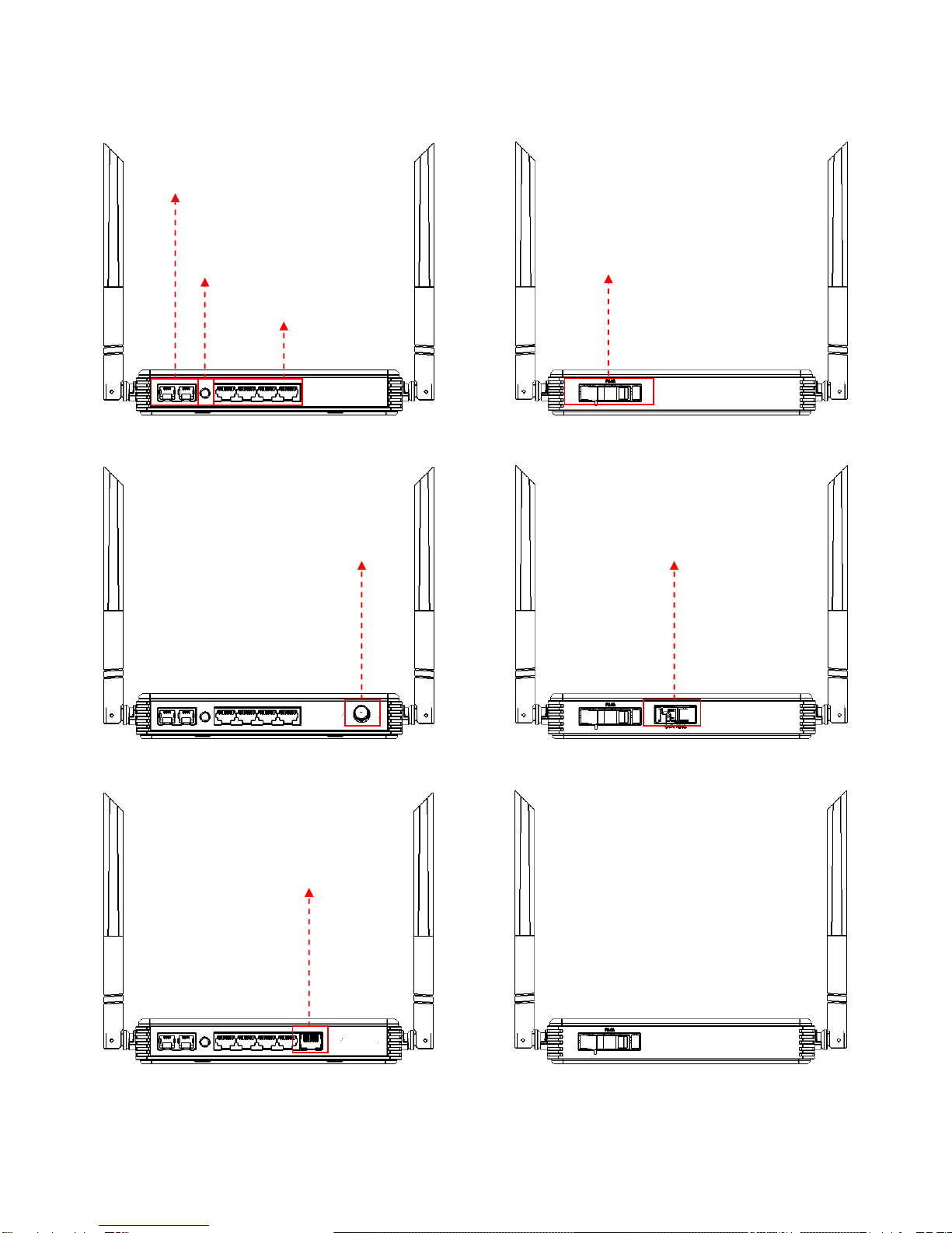
1.4 Connecting the Residential Gateway...................................................................................................................................... 11
1.5 RF over Fiber (With RF Receiver only) .................................................................................................................................... 12
1.6 LED Descriptions ..................................................................................................................................................................... 13
2. WEB MANAGEMENT ......................................................................................................................... 14
2.1 The Concept of IP address ...................................................................................................................................................... 14
2.2 Start Configuring .................................................................................................................................................................... 14
2.3 Introduction to Sub-Menus..................................................................................................................................................... 16
2.4 Setup ...................................................................................................................................................................................... 18
2.4.1 System Information ........................................................................................................................................................ 19
2.4.2 Basic Setup ..................................................................................................................................................................... 21
2.4.3 DDNS............................................................................................................................................................................... 31
2.4.4 Network Setup................................................................................................................................................................ 33
2.4.5 Routing Setup ................................................................................................................................................................. 36
2.5 WiFi ........................................................................................................................................................................................ 38
2.5.1 Wireless Setup................................................................................................................................................................ 38
2.5.2 Wireless Security ............................................................................................................................................................ 43
2.5.3 MAC Access Filter ........................................................................................................................................................... 48
2.6 Security................................................................................................................................................................................... 50
2.6.1 Firewall ........................................................................................................................................................................... 50
2.6.2 Packet Filter.................................................................................................................................................................... 51
2.6.3 URL Filter ........................................................................................................................................................................ 55
2.6.4 VPN Passthrough ............................................................................................................................................................ 56
2.6.5 UPnP ............................................................................................................................................................................... 57
2.6.6 DDoS ............................................................................................................................................................................... 58
2.7 Application ............................................................................................................................................................................. 62
2.7.1 Port Forwarding.............................................................................................................................................................. 62
2.7.2 Port Triggering ................................................................................................................................................................ 64
2.7.3 DMZ ................................................................................................................................................................................ 66
2.8 QoS ......................................................................................................................................................................................... 68
2.8.1 QoS Priority .................................................................................................................................................................... 68
2.8.2 QoS Ratelimiter .............................................................................................................................................................. 73
2.9 SIP........................................................................................................................................................................................... 75
2.9.1 Basic Settings.................................................................................................................................................................. 75
2.9.2 Account Settings ............................................................................................................................................................. 77
2.9.3 Server Settings................................................................................................................................................................ 78
2.10 Voice ..................................................................................................................................................................................... 80
2.10.1 Voice Settings ............................................................................................................................................................... 81
2.10.2 Call Service ................................................................................................................................................................... 83
2.10.3 FAX Port Settings .......................................................................................................................................................... 85
2.10.4 FAX Settings .................................................................................................................................................................. 87
2.10.5 General Dialing Settings ............................................................................................................................................... 88
2.10.6 Phone Book .................................................................................................................................................................. 90
2.10.7 Dialing Plan ................................................................................................................................................................... 91

5
2.11 IPTV ...................................................................................................................................................................................... 93
2.11.1 IGMP Control ................................................................................................................................................................ 93
2.12 CATV(available for RF module only) ..................................................................................................................................... 95
2.12.1 CATV Control................................................................................................................................................................. 95
2.13 Management........................................................................................................................................................................ 95
2.13.1 Auto Provision (TR069/DHCP) ...................................................................................................................................... 95
2.13.2 SNMP ............................................................................................................................................................................ 96
2.14 Administration...................................................................................................................................................................... 98
2.14.1 Device Access ............................................................................................................................................................... 98
2.14.2 Interface Mgmt............................................................................................................................................................. 99
2.14.3 Time............................................................................................................................................................................ 101
2.14.4 Syslog.......................................................................................................................................................................... 102
2.14.5 Diagnostics ................................................................................................................................................................. 103
2.14.6 User Privilege.............................................................................................................................................................. 105
2.14.7 Backup/Restore .......................................................................................................................................................... 106
2.14.8 Factory Default ........................................................................................................................................................... 107
2.14.9 Firmware Upgrade...................................................................................................................................................... 108
2.14.10 Save & Restore.......................................................................................................................................................... 109
2.15 Status.................................................................................................................................................................................. 110
2.15.1 WAN............................................................................................................................................................................ 110
2.15.2 LAN ............................................................................................................................................................................. 111
2.15.3 WLAN.......................................................................................................................................................................... 112
2.15.4 Routing Table .............................................................................................................................................................. 113
2.15.5 Line Status .................................................................................................................................................................. 114
2.15.6 Port Status .................................................................................................................................................................. 114
3. SNMP NETWORK MANAGEMENT .................................................................................................... 116
APPENDIX A: Set Up DHCP Auto-Provisioning ...................................................................................... 117
APPENDIX B: DHCP Text Sample .......................................................................................................... 122

6
1. INTRODUCTION
Thank you for purchasing the WLAN Residential Gateway which is designed to aim at FTTX
applications. This WLAN Residential Gateway provides four TP ports for LAN applications, one
fiber optic or TP port for WAN, two sets of FXS telephony ports and built-in IEEE 802.11b/g/n
wireless LAN (To use CATV application, please purchase the WLAN Residential Gateway with RF
module installed). The combination of wireless and VoIP function provides users not only more
flexible ways to enjoy bandwidth-intensive services but also more secure internetwork connections
by implementing packet or URL filtering policies.
The wireless function of this Gateway conforms to IEEE 802.11n standards that can provide speed
rate up to 30Mbps or 300Mbps when used with other 802.11n wireless products (the speed rate
varies depends on the model that your purchase). To enhance wireless connections to reach
further, the antennas, dispersing the same amount of power in all directions, can be used to
receive and deliver stable and high-gain transmissions. The WLAN Residential Gateway also
supports WPA/WPA2/WPA-Mixed authentication methods and 64/128-bit data encryption to
implement strict security protection so as to prevent your wireless networks from unauthorized
uses or possible malicious attacks. Other security mechanisms provided that can protect your
network including the uses of disabling SSID broadcast function, MAC filtering, URL filtering,
DDoS protection.
For VoIP applications, the internationally recognized standards, SIP (Session Initiation Protocol),
have been employed to manage multimedia communication sessions so that users can use
traditional analog telephones to make telephone calls to IP telephones over the Internet. Calls
received from IP telephones work exactly the same as you would expect from the traditional
telephone service. Other WLAN Residential Gateway’s features are: Voice Activity Detection (VAD)
/ Silence Suppression which reduces the bandwidth that a call uses by not transmitting when you
are not speaking; Comfort Noise Generation that is the background noise the device generates to
fill moments of silence when the other device in a call stops transmitting because the other party is
not speaking (as total silence could easily be mistaken for a lost connection); Echo Cancellation
which is WLAN Residential Gateway’s supporting G.168, an ITU-T standard for eliminating the
echo caused by the sound of your voice reverberating in the telephone receiver while you talk.
The WLAN Residential Gateway is mainly dedicated to the FTTX broadband service providers
who look for a way of delivering multiple IP services to the home users. The fiber optic port
supports connection distance from 2KM to 20KM or further than 100KM by using multi-mode
optical fiber, single-mode optical fiber (SMF), or bi-direction SMF. The transmission distance varies
depending on the fiber transceiver that your purchase. For detailed information about fiber
transceiver, please refer to Fiber Transceiver Information PDF in Documentation CD-ROM. To
easily manage and maintain the device, advanced network settings are configurable via Web-
based Management such as Firmware upgrade. The featured NAT and DHCP server functions
also allow you to use a hub or switch to establish a private network depending on your personal
needs that allows multiple computers to share a single Internet connection.

7
1.1 Front, Rear and Top-Front Panel
Figure 1-1~1-13 show the front, back and top views of the 802.11n device:
Figure 1-1. Front Panel of VRGIII-31412SFP-N and VRGIII-31412-N-DR Figure 1-2. Back Panel of VRGIII-31412SFP-N and VRGIII-31412-N-DR
Figure 1-3. Front Panel of VRGIII-31412-N-DR-RF Figure 1-4. Back Panel of VRGIII-31412-N-DR-RF
Figure 1-5. Front Panel of VRGIII-31412-CW-N-DR Figure 1-6. Back Panel of VRGIII-31412-CW-N-DR
Telephony Port 1-2
(RJ-11 Connection)
Smart
Lighting
Control
LAN Port 1-4
(RJ-45 Connection)
Ethernet Optical
WAN Port
CATV RF
CATV RF Input
Copper WAN Port
(RJ-45 Connector)

8
Figure 1-7. Front Panel of VRGIII-31412-CW-N-RF Figure 1-8. Back Panel of VRGIII-31412-CW-N-RF
Figure 1-9. Front Panel of VRGIII-31412TP-N Figure 1-10. Back Panel of VRGIII-31412TP-N
Figure 1-11. Left Panel Figure 1-12. Right Panel
WPS Button
Reset Button
Power Jack Connector

9
Figure 1-13. Top Panel
LED

10
1.2 Management Options
Management options available in this Residential Gateway are listed below:
Web Management
Web Management is of course done over the network. Once the Residential Gateway is on
the network, you can login and monitor the status remotely or locally by a web browser.
Local console-type Web management, especially for the first time use of Residential
Gateway to set up the needed IP, can also be done through any of the four
10/100/1000Base-T 8-pin RJ-45 ports located at the front panel of the Residential Gateway.
Direct RJ45 LAN cable connection between a PC and Residential Gateway is required for
this.
SNMP Management (See 3. SNMP NETWORK MANAGEMENT for detailed descriptions.)
1.3 Interface Descriptions
Before you start to configure your device, it is very important that the proper cables with the
correct pin arrangement are used when connecting the Residential Gateway to other devices such
as switch, hub, workstation, etc. The following describes correct cables for each interface type.
WAN 100/1000Base-X or 1000Base-X Fiber Port (With VRGIII-31412-N-DR and VRGIII-
31412-N-DR-RF)
1x100/1000Base-X or 1000Base-X Fiber port is located within the back panel of the
Residential Gateway. This port is primarily used for up-link connection and will operate at
100M or 1000M Full Duplex mode. Duplex SC or WDM Simplex SC types of connectors are
available. Use proper multimode or single-mode optical fiber to connect this port with other
Fast Ethernet Fiber port.
WAN 100/1000Base-X or 1000Base-X SFP Port (With VRGIII-31412SFP-N, VRGIII-
31412SFP-N-DR, VRGIII-31412-CW-N-DR and VRGIII-31412-CW-N-DR-RF)
1x1000Base-X or 100/1000Base-X SFP Port is located within the back panel of the
Residential Gateway. The small form-factor pluggable (SFP) is a compact optical
transceiver used in optical data communication applications. It interfaces a network device
mother board (for a switch, router or similar device) to a fiber optic or unshielded twisted
pair networking cable. It is a popular industry format supported by several fiber optic
component vendors.
SFP transceivers are available with a variety of different transmitter and receiver types,
allowing users to select the appropriate transceiver for each link to provide the required
optical reach over the available optical fiber type. SFP transceivers are also available with a
"copper" cable interface, allowing a host device designed primarily for optical fiber
communications to also communicate over unshielded twisted pair networking cable.
SFP slot for 3.3V mini GBIC module supports hot swappable SFP fiber transceiver. Before
connecting the other switches, workstation or Media Converter, make sure both side of the
SFP transfer are with the same media type, for example, 1000Base-SX to 1000Base-SX,
1000Bas-LX to 1000Base-LX, and check the fiber-optic cable type matches the SFP
transfer model. To connect to 1000Base-SX transceiver, use the multi-mode fiber cable

11
with male duplex LC connector type for one side. To connect to 1000Base-LX transfer, use
the single-mode fiber cable with male duplex LC connector type for one side.
LAN 10/100/1000Base-TX RJ-45 Ports
4x10/100/1000Base-T 8-pin RJ-45 ports are located at the front panel of the Residential
Gateway. These RJ-45 ports allow user to connect their traditional copper based
Ethernet/Fast Ethernet devices into network. All these ports support auto-negotiation and
MDI/MDIX auto-crossover, i.e. either crossover or straight through CAT-5 cable may be
used.
Since there is no separated RJ-45 Management Console port for this Residential Gateway,
however any of these four 10/100/1000Base-T RJ-45 ports can be used temporarily as the
RJ-45 Management Console Port for local management. This temporary RJ-45
Management Console Port of the Residential Gateway and a RJ-45 LAN cable for PC
connections are required to connect the Residential Gateway and a PC. Through these, the
user then can configure and check the Residential Gateway even when the network is
down.
FXS RJ-11 Telephony ports
There are two FXS RJ-11 telephony ports at the front panel of the Residential Gateway.
The “Phone”ports are for users to connect their traditional telephones.
1.4 Connecting the Residential Gateway
Before starting to configure the Residential Gateway, you have to connect your devices correctly.
When you connect your device correctly, the corresponding LEDs will light up.
Connect the power adaptor to the power port of the Residential Gateway on the back, and
the other end into a wall outlet. The Power LED should be ON.
The system starts to initiate. After completing the system test, the Status LED will light up.
CAUTION: For the first-time configuration, connect one end of an Ethernet patch cable (RJ-
45) to any ports on the front panel and connect the other end of the patch cable (RJ-45) to
the Ethernet port on Administrator computer. LAN LED for the corresponding port will light
up.
Connect one end of an Ethernet patch cable (RJ-45) to other LAN ports of the Router and
connect the other end of the patch cable (RJ-45) to the Ethernet port on other computers or
Ethernet devices to form a small area network. The LAN LED for that port on the front panel
will light up.
Connect the Fiber cable provided from your service provider to the WAN Fiber port on the
back panel, the WAN LED will light up and blinking if data are transmitting.

12
1.5 RF over Fiber (With RF Receiver only)
Fiber Optic RF Receiver with SC/APC connector is located in the middle of the back panel of the
WLAN Residential Gateway. This port is primarily used for CATV RF link connection and will
operate at output level greater than 24dBmV@-5dBm of optical input with 77 NTSC or 60 PAL
channels of loading. Use proper RF optical fiber to connect this port with other fiber port at the
CATV head end. Also use TV Coaxial Cable to connect the TV with the TV coaxial cable female
connector located in the right corner of the front panel of the WLAN Residential Gateway.

13
1.6 LED Descriptions
LED
Color
Operation
Power
Off
Power is off.
Green
Power is functioning normally.
STATUS
Green
System is ready.
Orange
System is not ready.
Orange blinking
Insert a pin or paper clip to press the Reset button for 3
seconds to restart the device. The STATUS LED will blink
in orange once.
Insert a pin or paper clip to press the Reset button for 10
seconds to reset the device to factory defaults. The
STATUS LED will blink in orange three times.
WAN
Off
The port link is off or it is up in 10Mbps.
Green
The link is up and works at 100Mbps.
Orange
The link is up and works at 1000Mbps.
Blinking
The traffic is present.
LAN 1
Off
The port link is off or it is up in 10Mbps.
Green
The link is up and works at 100Mbps.
Orange
The link is up and works at 1000Mbps.
Blinking
The traffic is present.
LAN 2
Off
The port link is off or it is up in 10Mbps.
Green
The link is up and works at 100Mbps.
Orange
The link is up and works at 1000Mbps.
Blinking
The traffic is present.
LAN 3
Off
The port link is off or it is up in 10Mbps.
Green
The link is up and works at 100Mbps.
Orange
The link is up and works at 1000Mbps.
Blinking
The traffic is present.
LAN 4
Off
The port link is off or it is up in 10Mbps.
Green
The link is up and works at 100Mbps.
Orange
The link is up and works at 1000Mbps.
Blinking
The traffic is present.
Wi-Fi
Off
WLAN link is off.
Green
WLAN link is up
Green blinking
The traffic is present.
WPS
Off
WLAN link is off.
Green
WPS is searching for the WPS client.
TEL 1
Off
Telephony Port 1 link is off.
Green
The telephone of Telephony Port 1 is off the hook.
Green Blinking
The telephone of Telephony Port 1 rings.
TEL 2
Off
Telephony Port 2 link is off.
Green
The telephone of Telephony Port 2 is off the hook.
Green Blinking
The telephone of Telephony Port 2 rings.

14
2. WEB MANAGEMENT
This chapter describes how to manage the Residential Gateway through a Web browser. The IP
address concepts and gaining access to the Residential Gateway will be introduced first, and then
followed by web-based management instructions.
2.1 The Concept of IP address
IP addresses have the format n.n.n.n, for example 168.168.8.100.
IP addresses are made up of two parts:
The first part (168.168 in the example) refers as network address identifies the network on
which the device resides. Network addresses are assigned by three allocation
organizations. Depending on your location, each allocation organization assigns a globally
unique network number to each network that wishes to connect to the Internet.
The second part (8.100 in the example) identifies the device within the network. Assigning
unique device numbers is your responsibility. If you are unsure of the IP addresses
allocated to you, consult the allocation organization from which your IP addresses were
obtained.
Remember that no two devices on a network can have the same address. If you connect to the
outside world, you must change all the arbitrary IP addresses to comply with those you have been
allocated by the allocation organization. If you do not do this, your outside communications will not
operate.
A subnet mask is a filtering system for IP addresses. It allows you to further subdivide your
network. You must use the proper subnet mask for proper operation of a network with subnets
defined.
2.2 Start Configuring
The Residential Gateway can be managed via a Web browser. However, before doing so, you
must assign a unique IP address to the Residential Gateway. Use a RJ-45 LAN cable and any of
the four 10/100/1000Base-T RJ-45 ports of Residential Gateway as the temporary RJ-45
Management console port to login to the Residential Gateway and set up the IP address for the
first time. (The default IP is “192.168.0.1”. You can change the Residential Gateway’s IP to the
needed one in the WAN Settings under Network Configuration menu.)
Follow these steps to manage the Residential Gateway through a Web browser:
Use one of the four 10/100/1000Base-T RJ-45 ports as the temporary RJ-45 Management
console port to set up the assigned IP parameters of the Residential Gateway.
1. IP address
2. Subnet Mask
3. Default gateway IP address, if required
Run a Web browser and specify the Residential Gateway’s IP address to reach it. (The
default IP of Residential Gateway is “192.168.0.1” before any changes.)

15
Login to the Residential Gateway to reach the Main Menu.
Once you gain the access, a Login window appears like the following:
Enter the authorized user name and password then click “Login”. The default user name is
admin and without a password (leave this field blank).
After a successful login, the following Residential Gateway Main Menu screen appears.
NOTE: By default, the remote access to the Residential Gateway is disabled. If you would
like to login the Residential Gateway from WAN port or ports assigned in Bridge Mode, you
must create a management interface in Basic Setup under the Setup Menu Bar and
enable it. Then, specify the IP address (if necessary) of the management computer and
specify Http port number for remote login in Device Access under the Administration
Menu Bar. Once completed, you can type in the IP address of the WAN management
interface and Http port number in URL field of your web browser like this
“192.168.1.198:8888”to access to web management.

16
2.3 Introduction to Sub-Menus
If you successfully login to the web management, the first page you will see is as follows:
Main Menu Bar At the top of the screen page is the Main Menu bar. It contains the following
main tabs:
Setup -To check or configure basic settings of the Residential Gateway, such as WAN
and LAN Settings, DHCP, NAT, VLAN, DDNS, Static Routing etc.
WiFi -To configure the WiFi settings of the Residential Gateway.
Security -To configure the security policies of the Residential Gateway, such as Firewall,
Packet Filter, URL Filter, VPN Passthrough, UPnP, SIP ALG and DDoS.
Applications -To configure the port forwarding function, port triggering function and
DMZ.

17
Qos -To configure the QoS settings and the rate limit of the Residential Gateway
SIP Settings -To configure SIP settings, such as SIP Basic/Advanced/Account Settings.
VoIP Settings -To configure VoIP settings, such as Voice, Phone Book, Call server,
FAX and FXS port settings, etc.
TV -To configure the IGMP settings and to enable or disable CATV module. And this tab
is only available for the WLAN Residential Gateway with RF module installed.
Management -To enable or disable Auto-provision, TR069 and SNMP for management.
Administration -To configure Device Access, Interface Management, system
Date/Time setting, Syslog, Ping test, User Privilege, Bakc/Restore, Factory Default and
Firmware Update.
Status -To show the current status of each interface and the basic information of the
Residential Gateway.
And note that when a main tab appears in the dark blue background, it is currently selected.
Sub Menu Bar Below the Main Menu Bar is the Sub Menu Bar. The Sub Menu Bar includes the
items which are associated to the selected main tab.
The area below the Sub Menu Bar includes two sub parts.
Configuration Area The part in the right side of the screen page is the configuration area.
Select a tab in the Sub Menu Bar for a feature. Then, you can find the parameters which you can
configure for this feature in the configuration area.
Section Panel This is a panel in the left side of the configuration area which displays the
sections available in the configuration area. The sections are the outline for the parameters of this
screen page.

18
Below is the brief description for each sub-menu. For detailed function explanations, please refer
to the individual section.
2.4 Setup
Select Setup from the Main Menu bar. Then you can see the sub-items –System Information,
Basic Setup,DDNS, Network Setup and Routing Setup –on the sub menu bar.

19
2.4.1 System Information
Select System Information from the Setup sub menu bar. Then, System Information screen
page appears as follows:
This page displays basic information of the Residential Gateway and information about the SFP
transceiver plugged in the WAN port. And for more details, please refer to the description of the
individual section below.
System This is a view-only section which displays basic system information of the Residential
Gateway. Below is a description of each item in this section.
Company Name —This is the name of the manufacturer.
System Name —This is the model name of the Residential Gateway.
System Object ID —This is the predefined system OID of the Residential Gateway.

20
System S/N —This is the serial number of the Residential Gateway.
Firmware Version —This is the current firmware version of the Residential Gateway.
Host Name —This is the host name of the Residential Gateway.
Date & Time —This is the time of the internal clock of the Residential Gateway.
Up Time —This is the time period since the Residential Gateway has been powered on
Fiber Information This is a view-only section which displays information about the fiber
transceiver in the fiber WAN port. Below is a description for each item in this section.
Connector —This is the type of the fiber connector in the fiber WAN port.
Vendor —This is the name of the manufacturer.
Vendor SN —This is serial number of the SFP transceiver.
Product Name —This is the model name of the fiber transceiver.
Speed —This is the maximal link speed which the fiber transceiver supports.
Wave Length —This is the the receiving and transmitting wave length of this fiber..
Distance —This is the maximal transmission distance which the fiber transceiver
supports.
This manual suits for next models
7
Table of contents
Other CTS Gateway manuals