EQUYSIS ULTRA-E-F User manual

ULTRA-E-F
Transit Time Ultrasonic Flow Meter
Clamp-on
Manual

CONTENTS
PART-1 INTRODUCTION ...................................................................................................1
General ...............................................................................................................................................1
Principleof measurement.................................................................................................................... 1
Applications........................................................................................................................................2
Features ..............................................................................................................................................2
Specifications .....................................................................................................................................3
Parts Identification...............................................................................................................................4
PART-2 CLAMP-ON TRANSDUCER INSTALLATION.................................................... 6
General ...............................................................................................................................................6
Mounting Location ............................................................................................................................ 6
Transducer Spacing ............................................................................................................................7
Transducer Mounting..........................................................................................................................8
Transducer Mounting Inspection and CouplantApplication..............................................................13
PART-3 TRANSMITTER INSTALLATION AND OPERATION INSTRUCTIONS ...14
Transmitter Installation .....................................................................................................................14
Transmitter Wirings............................................................................................................................... 15
KeypadConfiguration...................................................................................................................... 16
PART-4 WINDOWS DISPLAYEXPLANATIONS ..........................................................20
PART-5 OUTPUT FUNCTIONS ........................................................................................28
4-20mAOutput..........................................................................................................................28
OCT Pulse Output...........................................................................................................................28
RelayOutput..............................................................................................................................29
RS485 Output....................................................................................................................................... 29
MODBUS-RTU Protocol................................................................................................................29
Data Storage Function ....................................................................................................................31
PART-6 HOW TO USE MENU FUNCTIONS..................................................................33
Use Menu Windows for Transducer Mounting Inspection..............................................................33
How to Judge Whether the Instrument works Well on Site.............................................................34
How to Judge the LiquidFlowing Direction..............................................................................35
How to Reset theDefault Setups ...............................................................................................35
How to Stabilize the Flow...............................................................................................................36
How to Use the Low FlowCutoff Function....................................................................................36
How to Setup Zero Point ................................................................................................................36
How to Use Scale Factor ...........................................................................................................36
How to Do When all keys or ENTER Key is invalid................................................................37
How to Set Date and Time.................................................................................................................37
ON/OFFTotalizer.................................................................................................................. 37
Units Options...........................................................................................................................37

PART-7 TROUBLESHOOTINGAND FAQ...............................................................................38
Troubleshooting....................................................................................................................................38
Frequently Asked QuestionsandAnswers......................................................................................40
PART-8 WARRANTYAND SERVICE ..............................................................................42
Warranty.......................................................................................................................................................42
Service.............................................................................................................................................42
APPENDIX 1 INSERTION TRANSDUCER INSTALLATION.........................................43
A, Menu Configuration..........................................................................................................................43
B, Installation Locating..........................................................................................................................43
C, Mountingthe Transducers................................................................................................................46
D, Transducer wirings...........................................................................................................................47
E, How to Obtain Good Signal Strength andSignalQuality.................................................................48
APPENDIX 2 ENERGYFUNCTION INSTRUCTION...................................................49
1. Introduction ................................................................................................................................. 49
2. Wires Connection..............................................................................................................................49
3. EnergyCalculation ...........................................................................................................................49
4. Temperature Range ...........................................................................................................................50
5. Pt1000 Temperature Sensors.............................................................................................................50
6. Clamp-On TemperatureSensors Installation.....................................................................................50
7. Insertion TemperatureSensors Installation .......................................................................................51
APPENDIX 3 MOUNTING FRAME INSTALLATION.......................................................52
0B
Int
1
ro
.
duction
........................................................................................................................................ 52
1B-2M. Mounting Frame Installation ..........................................................................................................52
Parts List of M-Mounting Frame...................................................................................................................52
Installation Steps for V and W Transducer Mounting Methods .....................................................................53
Installation Steps for Z and N Transducer Mounting Methods......................................................................56
3. S-Mounting Frame Installation.........................................................................................................58
Parts List of S-Mounting Frame....................................................................................................................58
Installation Steps for V and W Transducer Mounting Methods .....................................................................59
Installation Steps for Z and N Transducer Mounting Methods......................................................................60
APPENDIX 4 FUILD CHARACTERISTIC (SOUND SPEED)......................................62
1. Fluid Properties ................................................................................................................................62
2. Water Sound Speed...........................................................................................................................63
3. Pipe Material SoundSpeed Table................................................................................................................64

1
ULTRA-E-F
PART-1 INTRODUCTION
General
It is the engineers and technicians' hope to measure the flow on the non-invasive pipeline
reliably. Series ULTRA-E-F are state-of–the-art universal transit-time ultrasonic flow meters,
fit to measure flow of full pipe line, providing a measuring system with unsurpassed accuracy,
versatility, ease of installation and dependability. Although designed primarily for cleaner
liquids, the flow meter is tolerant of liquids with the small amount of air bubbles or suspended
solids found in most industrial environments.
Principle ofmeasurement
The ULTRA-E-F ultrasonic flow meter is designed to measure the fluid velocity of liquid
within a closed pipe. The transducers are a non-invasive, clamp-on type, which will provide
benefits of non-fouling operation and easy installation.
The ULTRA-E-F transit time flow meter utilizes two transducers that function as both ultrasonic
transmitters and receivers. The transducers are clamped on the outside of a closed pipe at a
specific distance from each other. The transducers can be mounted in V-method where the
sound transverses the pipe twice, or W-method where the sound transverses the pipe four times,
or in Z-method where the transducers are mounted on opposite sides of the pipe and the sound
crosses the pipe once. This selection of the mounting method depends on pipe and liquid
characteristics. The flow meter operates by alternately transmitting and receiving a frequency
modulated burst of sound energy between the two transducers and measuring the transit time
that it takes for sound to travel between the two transducers. The difference between the transit-
time is directly and exactly related to the velocity of the liquid in the pipe, as shown in Figure 1.
V=K*
△
t
Q=S*V
Where: V Liquidvelocity
K Constant
△
t
Differenceintimeofflight
Q Flow rate
S Sectional area ofpipe
Figure 1

2
ULTRA-E-F
Applications
1. Water,sewage (with low particle content) and sea water
2. Water supply and drainagewater
3. Process liquids; Liquors
4. Milk, yoghourtmilk
5. Gasoline; Kerosene; Diesel;Oil
6. Powerplant
7. The flowpatrolling and examining
8. Metallurgy, Laboratory
9. Energy-conservation, economize onwater
10. Food and medicine
11 Heat measures, Heatbalance
12 On-the-spot check-up, standard, the data are judged, Pipeline leak detection
Features
Built-In large capacity memory and USB data download function. The downloaded data can
be opened by EXCELdirectly.
Clamp-On transducers are easy to install, non-invasive, cost effective, and require no pipe
cutting or processing interrupt. Since the transducers do not contact with the liquid, fouling
and maintenance areeliminated.
Insertion transducers are hot-tapped installation, no pipe line flow interrupted.
Apair of sensors can satisfy different materials , wide different pipe diameters
Clear, user-friendly menu selections make ULTRA-E-F series simple and convenient to use
4 Lines display, can display total flow, flow rate, velocity and meter run status. Parallel
operation of positive, negative and net flow totalizes.
U.S., British and Metric measurement units are available. Meanwhile, almost all-universal
measurement units worldwide may be selected to meet customer’s requirements.
The heat measurement by configuring with Pt1000 temperature sensors.
Remote operation by the wireless handheld operator. No matter the pipeline in high altitude
or underground, users can install or adjust the transducer more convenient. The
communication range is about 100 meters in free range space, and 10 meters in through-wall
distance. Compared to the short distance of Bluetooth, it is more convenient and practical.
This wireless handheld operator has wireless remote reading function and it also can
operate the meters instead of paneloperations.

3
ULTRA-E-F
Specifications
Transmitter
Transducer
Description
Specifications
Liquid types
Virtually most any liquid containing less than 5% total suspended solids
(TSS) or aeration.
Suited Liquid temperature
Standard Temp. Transducer: -40 to 240F [-40 to 121℃]
High Temp. Transducer : -40 to 480F [-40 to 250℃] for Clamp-on
-40 to 300F [-40 to 150℃] for Insertion
Transducer to Transmitter
Cable distance
Shield cable, standard 6 meters, (opt) Lengths to 300 meters
Pipe size
M transducer: 40-1000mm pipe I.D; L transducer: 1000-4500mm; S&K
transducer: 20-50mm; Insertion transducer: 80-4500mm
Pipe material
All kind of steel and cast iron, PVC etc.
Description
Specifications
Principle of Measurement
Principle of Transit Time, DSP technology and MultiPulse Transducer
Technology
Power Requirements
100-240VAC 50/60Hz ±15% or 12-36VDC
Velocity
0.003 to 12 m/s, bi-directional
Outputs
Optional
All outputs are isolated from earth and system grounds.
Data storage function
4-20mA: 1000 ohm max, Accuracy: 0.1%
Frequency output: (From F.out), for flow rate or total flow
Relay output for total flow or alarm
RS485 (Modbus-RTU) output
Option: Wireless handheld operator, GPRS
Display
4 line×16 English letters LCD, it can display total flow, flow rate,
velocity and meter run statusetc.
Units
Rate
Totalizer
User Configured (English and Metric)
Flow Rate and Velocity Display
Forward total; Reverse total; Net Total(difference between forward and
reverse flow)
Ambient Conditions
-40 to 131F [-40 to 55℃], 0-95% relative humidity, non-condensing
Enclosure
NEMA 4X [IP65]
261H×193W×80D mm
Accuracy Flow Rate
±1.0% of reading at rates >0.5 m/s
±0.005 m/s of reading at rates<0.5 m/s
Repeatability
0.2%
Responding Time
500ms display refresh, sampling cycle 7.5ms
Security
Keypad lock and system lock, access code enable
Approvals(option)
ATEX (ExdⅡBT6) certified. (LCIE 09 ATEX 3088)
Other functions
Automatic record incident and functions of management of flow
Remember the state of the flow meter; Diagnosis

4
ULTRA-E-F
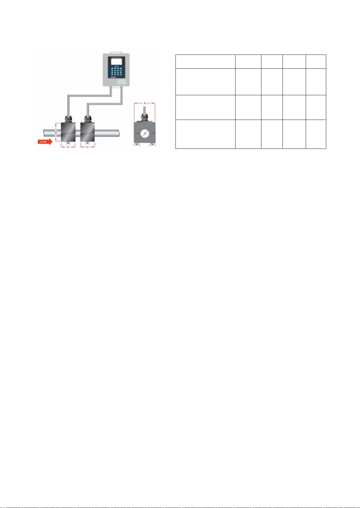
Parts Identification
Transmitters:
Standard wall-mounted
Transducers:
Ex-proof type (ATEX) K transducer High temperaturetransducer
S-Transducer M-Transducer L-Transducer
M-Mounting Frame (V method andZ method) S-Mounting Frame (V method and Zmethod)
Accessories:
Stainless Steel Strap Flexible belts Couplant
5
ULTRA-E-F
K mode transducers:
Size
A
B
C
D
K1:
3/4", 1"
55
39
42
34
K2:
3/4", 1", 1-1/4"
64
46
42
43
K3:
1-1/4", 1-3/4", 2"
80
46
42
61

6
ULTRA-E-F
PART-2 CLAMP-ON TRANSDUCER INSTALLATION
General
The transducers that are utilized by the Series ULTRA-E-F contain piezoelectric crystals for
transmitting and receiving ultrasound signals through walls of liquid piping systems. The
transducers are relatively simple and straight-forward to install, but spacing and alignment of
the transducers is critical to the system's accuracy and performance. Extra care should be taken
to ensure that these instructions are carefully executed.
Mounting of the clamp-on ultrasonic transit time transducers is comprised of three steps:
Selection of the optimum location on a piping system.
Entering the necessary parameters into the ULTRA-E-F keypad. (ULTRA-E-F will
calculate proper transducer spacing based on these entries (menu 25))
Pipe preparation and transducermounting.
MountingLocation
The first step in the installation process is the selection of an optimum location for the flow
measurement. For this to be done effectively, a basic knowledge of the piping system and its
plumbing is required.
An optimum location is defined as:
A piping system that is completely full of liquid when measurements are being taken. The
pipe may become completely empty during a process cycle - which will result in an error code
being displayed on the flow meter while the pipe is empty. Error codes will clear automatically
once the pipe is filled with liquid. It is not recommended to mount the transducers in an area
where the pipe may become partially filled. Partially filled pipes will cause erroneous and
unpredictable operation of the meter.
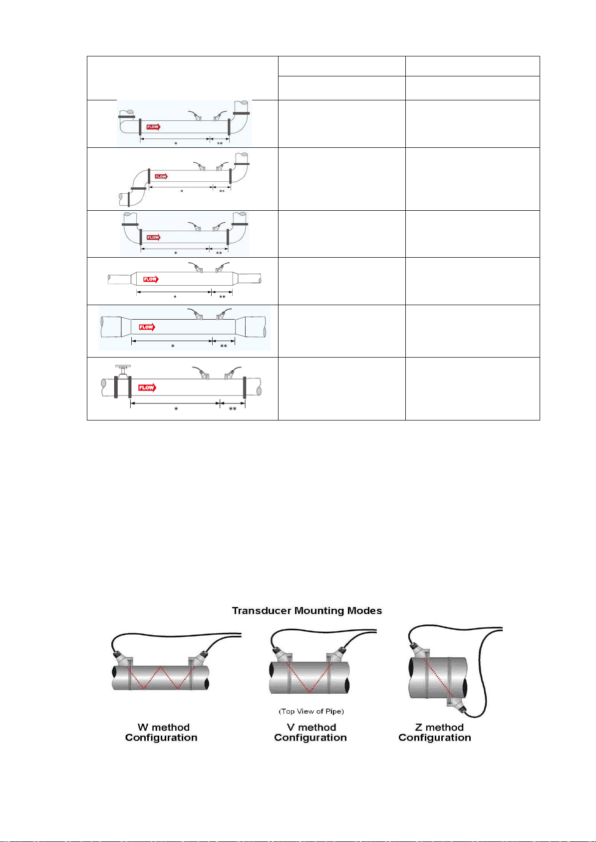
A piping system that contains lengths of straight pipe such as those described in Table
2.1. The optimum straight pipe diameter recommendations apply to pipes in both horizontal
and vertical orientation. The straight runs in Table 2.1 apply to liquid velocities that are
nominally 7 FPS [2.2 MPS]. As liquid velocity increases above this nominal rate, the
requirementfor straight pipe increases proportionally.
Mount the transducers in an area where they will not be inadvertently bumped or
disturbed during normal operation.
Avoid installations on downward flowing pipes unless adequate downstream head pressure
is present to overcome cavitations in the pipe.
Table 2.1 Requirement of Straight Pipe Length
7
ULTRA-E-F
Piping configuration
And transducer position
Upstream Dimension
Downstream Dimension
Pipe Diameters (*)
Pipe Diameters (**)
24
5
14
5
10
5
10
5
8
5
24
5
TransducerSpacing
ULTRA-E-F transducers are clamped on the outside of a closed pipe at a specific distance
from each other. The transducers can be mounted in V-mode where the sound transverses the
pipe two times, W-mode where the sound transverses the pipe four times, or in Z-mode where
the transducers are mounted on opposite sides of the pipe and the sound crosses the pipe once.
W-mode provides the longest sound path length between the transducers - but the weakest
signal strength. Z-mode provides the strongest signal strength - but has the shortest sound path
length.

8
ULTRA-E-F
The ULTRA-E-F system calculates proper transducer spacing by utilizing piping and
liquid information entered by the user.
The following information is required before programming the instrument. Note that much of
the data relating to material sound speed, viscosity and specific gravity are preprogrammed
into the ULTRA-E-F flow meter. This data only needs to be modified if it is known that a
particular liquid data varies from the reference value. Refer to Part 3 of this manual for
instructions on entering configuration data into the ULTRA-E-F flow meter via the meter
keypad.
1.
Pipe OuterDiameter
2.
Pipe wall thickness
3.
Pipe material
4.
Pipe sound speed
5.
Pipe relativeroughness
6.
Pipe line thickness
7.
Pipe linematerial
8.
Pipe line sound speed
9.
Fluid type
10.
Fluid sound speed
Nominal values for these parameters are included within the ULTRA-E-F operating system.
The nominal values may be used as they appear or may be modified if exact system values are
known.
After entering the data listed above, the ULTRA-E-F will calculate proper transducer spacing
for the particular data set. This distance will be in inches if the ULTRA-E-F is configured in
English units, or millimeters if configured in metric units.
TransducerMounting
After selecting an optimum mounting location and successfully determining the proper
transducer spacing, the transducers may now be mounted onto the pipe.
The transducers must be properly oriented on the pipe to provide optimum reliability and
performance. On horizontal pipes, the transducers should be mounted 180 radial degrees from
one another and at least 45 degrees from the top-dead-center and bottom-dead-center of the
pipe. See Figure 2.1. Figure 2.1 does not apply to vertically oriented pipes.

9
ULTRA-E-F
Pipe Preparation
Before the transducers are mounted onto the pipe surface, two areas slightly larger than the flat
surface of the transducer heads must be cleaned of all rust, scale and moisture. For pipes with
rough surfaces, such as ductile iron pipe, it is recommended that the pipe surface be ground flat.
Plastic pipes typically do not require surface preparation other than soap and water cleaning.
Observe Signal Strength while placing the transducers into position. Signal Strength can be
displayed on Menu 90.
V-Mode and W-Mode Installation
1. For ULTRA-E-F transducers, place a single bead of couplant, approximately 0.5 inch [15
mm] width, on the flat face of the transducer. See Figure 2.2. Generally, silicone-based grease
is used as an acoustic couplant, but any grease-like substance that is rated not to “flow” at the
temperature that the pipe may operate will be acceptable.
Figure 2.2
2.
P
lace the up
s
tream tra
ns
ducer in po
s
ition and
s
ecure
w
ith a mounting
s
trap.
S
trap
s
s
hould be
placed in the arched groove on the end of the transducer. A screw is provided to help hold the
transducer onto the strap. Verify that the transducer is stick to the pipe - adjust as necessary.
Tighten the transducer strap securely.
3.Place the downstream transducer on the pipe at the calculated transducer spacing. See
Figure 2.3. Using firm hand pressure, slowly move the transducer both towards and away
from the upstream transducer while observing Signal Strength. Clamp the transducer at the
position where the highest Signal Strength is observed. A Signal Strength (Menu 90) between
60 and 95 is acceptable.
4. If after adjustment of the transducers, the Signal Strength (Menu 90) does not rise to above
60, then an alternate transducer mounting method should be selected. If the mounting method
was W-mode, then reconfigure the ULTRA-E-F for V-mode, reset the ULTRA-E-F, move the
downstream transducer to the new location and repeat step 3.
10
ULTRA-E-F
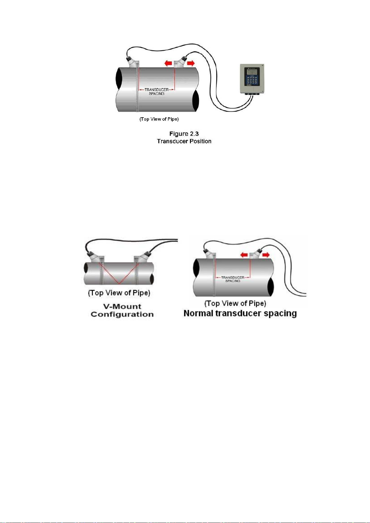
V-Mount is the STD installation method, it is convenient and accurate, Reflective type
(transducers mouthed on one side of the pipe) of installation used primarily on pipe size in the
(50mm~400mm) internal diameter range attention transducer designed parallel on the centre
line of installing the pipeline.
The spacing value shown on menu window M25 refers to the distance of inner spacing
between the two transducers. The actual transducers spacing should be as close as possible to
the spacing value. The transducer spacing is from the end of one transducer to another sensor.
The transducer mounting spacing is very important for Transit-time meters, and users need
mount transducers exactly according to the spacing distance value M25 displays after users
input proper parameter settings. M91 is only for reference, and just keep it within 97--103%
value range.
As the above figure shows, the normal transducer spacing refers to the distance between the
ends of the two transducers (as the two red lines indicate). And this spacing should be exactly
according to the value in M25. Note that this method suits for normal Small, Std. M and Large
transducer.
For Magnetic transducers, the definition of transducer spacing is the distance between the two
scale lines, just as showed bellow:

11
ULTRA-E-F
The value displayed in M25 for magnetic transducer spacing refers to the distance showed in
the above figure. (Note: The displayed value in M25 is larger than the distance between the
ends of the two magnetic transducers.) Users should mount the magnetic transducers with the
above showed spacing exactly according to the M25 value.
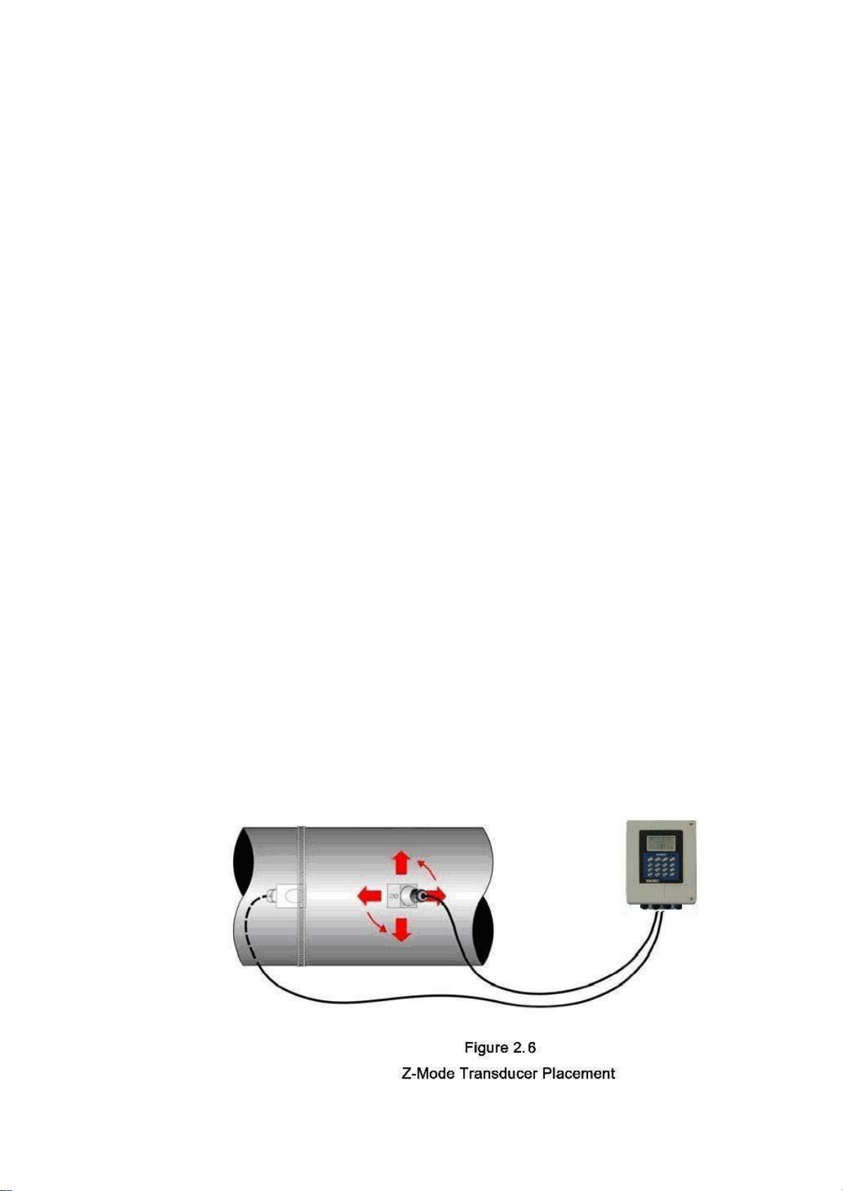
Z-Mode Installation
Z-mode installation method is suitable for S-Transducer, L-Transducer and the condition of
weak signal strength and/or inaccurate readings. The section below details a method for
properly locating the transducers on larger pipes. This method requires a roll of paper such as
freezer paper or wrapping paper, masking tape and a marking device.
1.
Wrap the paper around the pipe in the manner shown in Figure 2.4. Align the paper ends
to within 6 mm.
2.
Mark the intersection of the two ends of the paper to indicate the circumference. Remove
the template and spread it out on a flat surface. Fold the template in half, bisecting the
circumference. See Figure2.5.
3.
Crease the paper at the fold line. Mark the crease. Place a mark on the pipe where oneof
12
ULTRA-E-F
the transducers will be located. See Figure 2.1 for acceptable radial orientations. Wrap the
template back around the pipe, placing the beginning of the paper and one corner in the
location of the mark. Move to the other side of the pipe and mark the pipe at the ends of the
crease. Measure from the end of the crease directly across the pipe from the first transducer
location) the dimension derived in Step 2, Transducer Spacing. Mark this location on the
pipe.
4.
The two marks on the pipe are now properly aligned and measured.
If access to the bottom of the pipe prohibits the wrapping of the paper around the
circumference, cut a piece of paper to these dimensions and lay it over the top of the pipe.
Length = Pipe O.D. x 1.57; width = Spacing determined on Menu 25.
Mark opposite corners of the paper on the pipe. Apply transducers to these two marks.
5.
Place a single bead of couplant, approximately 0.5 inch [15 mm] width, on the flat face of
the transducer. See Figure 2.2. Generally, a silicone-based grease is used as an acoustic
couplant, but any grease-like substance that is rated to not “flow” at the temperature that the
pipe may operate at, will beacceptable.
a)
Place the upstream transducer in position and secure with a stainless steel strap or other.
Straps should be placed in the arched groove on the end of the transducer. A screw is
provided
b)
Try to help hold the transducer onto the strap. Verify that the transducer is true to the pipe
- adjust as necessary. Tighten transducer strap securely. Larger pipes may require more than
one strap to reach the circumference of the pipe.
6.
Place the downstream transducer on the pipe at the calculated transducer spacing. See
Figure 2.6. Using firm hand pressure, slowly move the transducer both towards and away
from the upstream transducer while observing Signal Strength. Clamp the transducer at the
position where the highest Signal Strength is observed. Signal Strength of between 60 and 95
percent is acceptable. On certain pipes, a slight twist to the transducer may cause signal
strength to rise to acceptablelevels.
7.
Secure the transducer with a stainless steel strap or other.

13
ULTRA-E-F
TransducerMounting Inspection and CouplantApplication
2.5.1 Transducer Mounting Inspection
It is very important to use menu operations for TRANSDUCER MOUNTING INSPECTION
and Estimation, Refer to 6.1, Use menu windows for Transducer Mounting Inspection.
2.52 Couplant Application
A, It is also very important for couplant application.
When mounting the transducers, apply just enough pressure so that the couplant fills the gap
between the pipe and transducer. Commonly, the Dow 732 for permanent and Dow 111 for
temporary installations, but Dow 111 has a better coupling effect. If Dow 732 was used,
ensure that no relative movement between the transducer and the pipe takes place during the
setting time and do not apply instrument power for at least 24 hours, Dow 111 also be used for
permanent installations(avoid rain or water etc.), setting time is not necessary. We recommend
using Dow 111 for permanent installing, and then use Dow732 around the transducer in order
to fix the transducer, waterproof cloth is recommended if the Transducers are installed outdoor.
Dow 112 for high temperatureapplication.
B, Transducers for High Temperature
Mounting of high temperature transducers is similar to ULTRA-E-F standard transducers; High
temperature installations require acoustic couplant Dow Corning 112 that is rated not to flow
at the temperature that will be present on the pipe surface.

14
ULTRA-E-F
PART-3 TRANSMITTER INSTALLATION AND OPERATION
INSTRUCTIONS
TransmitterInstallation
After unpacking, it is recommended to save the shipping carton and packing materials in case
the instrument is stored or re-shipped. Inspect the equipment and carton for damage. If there is
evidence of shipping damage, notify the carrier immediately.
The enclosure should be mounted in an area that is convenient for servicing, calibration or for
observation of the LCD reading.
1 Locate the transmitter within the length of transducer cable that was supplied with the
ULTRA-E-F system. If this is not possible, it is recommended that the cable be exchanged for
one that is of proper length. Transducer cables that are up to 990 feet [300 meters] may be
accommodated.
2.
Mount the ULTRA-E-F transmitter in a location that is:
♦
Where little vibrationexists.
♦
Protected from falling corrosivefluids.
♦
Within ambient temperature limits -40 to 131°F [-40 to 55°C]
♦
Out of direct sunlight. Direct sunlight may increase transmitter temperature to above the
maximum limit.
3.
Mounting: Refer to Figure 3.1 for enclosure and mounting dimension details. Ensure that
enough room is available to allow for door swing, maintenance and conduit entrances.
Secure the enclosure to a flat surface with four appropriate fasteners.
Figure 3.1 Mechanical Dimensions

15
ULTRA-E-F
4.
Conduit holes. Conduit hubs should be used where cables enter the enclosure. Holes not
used for cable entry should be sealedwith plugs.
NOTE: Use NEMA 4 [IP65] rated fittings/plugs to maintain the water tight integrity of the
enclosure. Generally, the left conduit hole (viewed from front) is used for line power; the
center conduit hole for transducer connections and the right hole are utilized for OUTPUT
wiring.
5 If additional holes are required, drill the appropriate size hole in the enclosure’s bottom.
Use extreme care not to run the drill bit into the wiring or circuit cards.
TransmitterWirings
Figure 3.2 Transmitter Wirings
To access terminal strips for electronic connectors, loosen the two screws in the enclosure door
and open the door. Guide the transducer terminations through the transmitter conduit hole
located in the bottom-center of the enclosure.
The terminals within ULTRA-E-F are a pluggable type - they can be removed wired and then
plugged back in. Connect the appropriate wires to the corresponding screw terminals in the
transmitter.
XDCR UP “+ - GND” is used to connect upstream transducer (Marked with a red sign),

16
ULTRA-E-F
.
∧
MENU
XDCR DN “+ - GND” is used to connect downstream transducer (Marked with a blue sign).
Connect line power to the screw terminals N, Land GND in the transmitter. The ground terminal
grounds the instrument, which is mandatoryfor safe operation.
DC Power connection: The ULTRA-E-F may be operated by a 12-36 VDC source, which is
capable of supplying a minimum of 3 Watts.
NOTES:
1)
The transducer cable carries low level high frequency signals. In general, it is not
recommended to add additional cable to the cable supplied with the transducers. If
additional cable is required, contact the factory to arrange an exchange for a transducer
with the appropriate length of cable. Cables to 300 meters are available.
2)
This instrument requires clean electrical line power. Do not operate this unit on circuits
with noisy components (i.e., fluorescent lights, relays, compressors, or variable frequency
drives). It is recommended not to run line power with other signal wires within the same
wiring tray orconduit.
Keypad Configuration
Keypad functions
After transducer and connection of appropriate power supply to ULTRA-E-F, keypad
configuration of the instrument can be undertaken. Generally, there should be no display of
error messages, and the flow meter will go to the most commonly used Menu Window Number
01 (short for M01) to display the Velocity, Flow Rate, Positive Totalizer, Signal Strength and
Signal Quality, based on the pipe parameters entering by the user or by the initial program.
The ULTRA-E-F contains a 16-key tactile keypad, allows the user to view and change
configuration parameters as shown below.
Follow these guidelines when using ULTRA-E-F
keypad:
0~ 9 and to input numbers anddecimal.
to backspace or delete characters to the left.
The arrow keys and
∨
To return to the last
menu or to open the next menu, are used to scroll
through menu configuration parameters; also acts
as “+” and “-” functions when entering numbers.
to select a menu. Press this key first,
input two menu numbers and then enter the
selected menu. For instance, to input a pipe Outside diameter, press MENU
1keys,
◀
1

17
ULTRA-E-F
∧
8
1
1
∧
,
∨
2
1
8
6
1
4
1
MENU
MENU
1
1
ENTER
ENTER
where “11” is the window Address to display the pipe outside diameter.
Keypad Operation
With all of the parameters entered, the instrument setup and measurement displays are
subdivided or consolidated into more than 100 independent windows. The user can view the
window menu, input parameters, modify settings or display measurement results. These
windowsarearrangedby2-digitserialnumbers(including
∧
sign)from00~94, thento
∧
0 ,
, etc.. Every window serial number, or so-called window Address code, has a defined
meaning. For instance, Window No.11 indicates the parameter input for pipe outside diameter,
while Window No.25 indicates the mounting distance between the transducers, etc. (Refer to
Part 4 –Windows Display Explanations).
The keypad shortcut to visit a specific window is to press the MENU key at any time, then
input the 2-digit window Address code. For instance, to input or check the pipe outside
diameter, justpress the keys for window Address code11.
Anothermethodto visit a particularwindow is to press
∨
and ENTER keys to scrollthe
menu. For instance, if the current window Address code is 66, press
∧
key to enter Window
No.65, press the again to enter Window No.64; then, press the key to back Window
No.65, and press the key again to enter WindowNo.66.
Example 1. To enter a pipe outside diameter of 218.6, the procedure is as follows:
Press keys to enter Window No.11 (the numerical value displayed currently
is a previous value). Now press ENTER key. The symbol ﹥and the flashing cursor are
displayed at the left end of the second line on the Screen. The new value can be entered by
press . .
Example 2. If the pipe material is “Stainless Steel”, press keys MENU to enter
Window No.14 first. Then press key to modify the options. Now, select the “1.
Stainless Steel ” option by pressing and keys, and then press key to confirm the
selection. It is possible to press the key to change the selection and wait until “1.
Stainless Steel” is displayed on the second line of the screen. Then press the ENTER key to
confirm.
M11
Outer Diameter
108 mm
M11
Outer Diameter
108 mm
﹥218.6
∧
∨
∧
∨
ENTER
Table of contents


