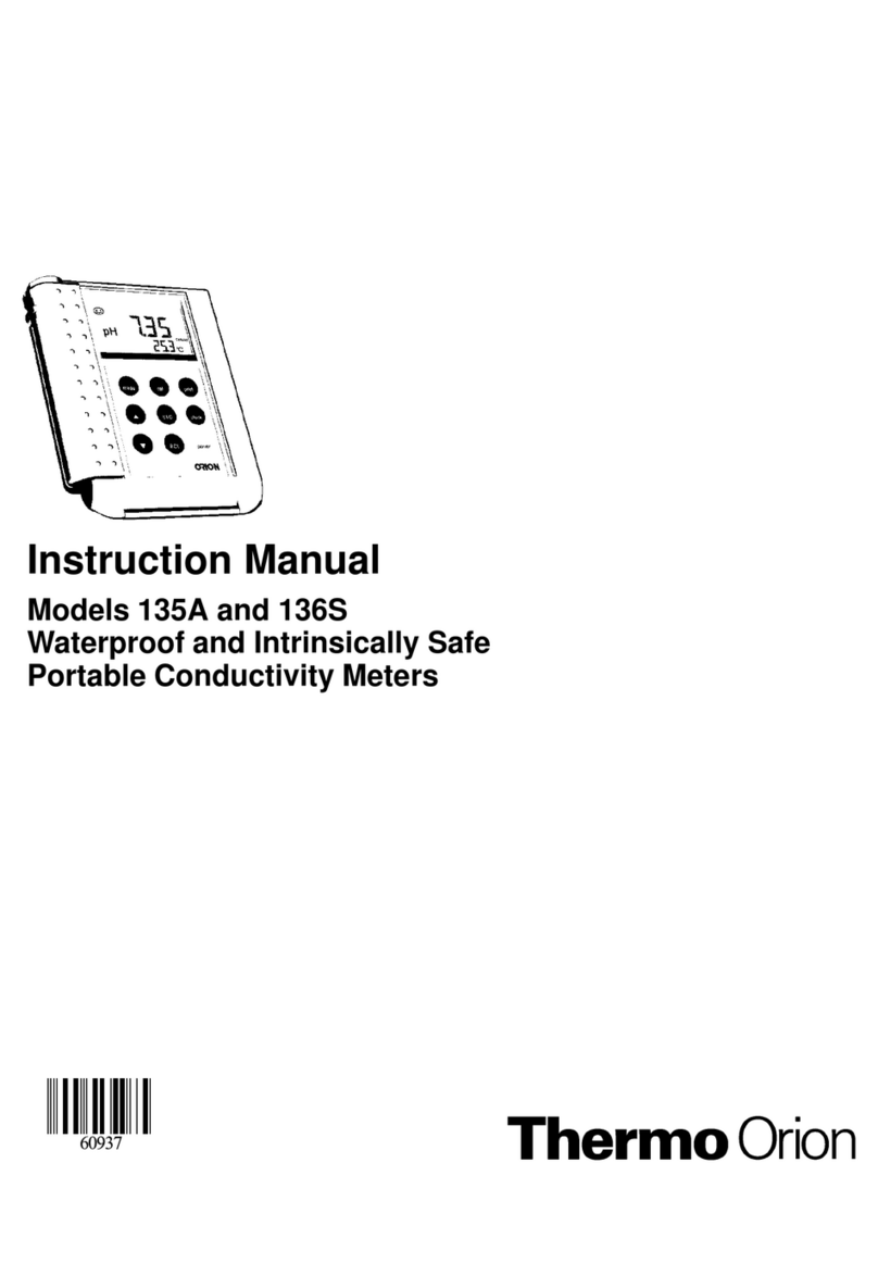
Thermo orion 410Aplus User manual

Benchtop pH and pH/ISE Meters
Models 410Aplus
420Aplus
520Aplus
525Aplus
710Aplus
720Aplus
920Aplus
INSTRUCTION MANUAL

Benchtop pH/ISE Meter Instruction Manual
Introduction 1
Chapter I
Introduction
Thermo Orion provides pH and ISE meters for every application from pH
measurements to advanced Ion Selective Electrode work. This manual
describes the operation and use of the Thermo Orion Model 410Aplus
pH/Temperature Meter, Model 420Aplus pH/mV/Temperature Meter, the
Model 520Aplus Advanced pH/mV/Temperature Meter, the Model
525Aplus Dual Channel pH/mV/Temperature Meter, the Model 710Aplus
pH/ISE Meter, the Model 720Aplus Dual Channel pH/ISE Meter, and the
Model 920Aplus Advanced pH/ISE Meter.
All meters are microprocessor-controlled and feature pH autocalibration,
sealed keypads, simultaneous temperature display and many other features.
The Models 410Aplus, 420Aplus and 710Aplus feature a custom LCD
display. The Models 520Aplus, 525Aplus, 720Aplus, and 920Aplus feature
a two color vacuum fluorescent display with a separate prompt line that
explains each step during calibration and measurement.
How to Use This Manual
For more detail on the operation of any of the models, please refer to the
Table of Contents for the page location of an operation of a particular meter
model. Troubleshooting instructions are common to all meters and this
information is located toward the end of this manual.
Explanation of key functions and additional reference information are not
required for calibration and measurement can be found in the appendices.

2
Benchtop pH/ISE Meter Instruction Manual

Benchtop pH/ISE Meter Instruction Manual
General Information 3
Chapter II
General Information
Models 410Aplus, 420Aplus, 710Aplus
General Information
The Model 410Aplus is a pH/Temperature Meter, the Model 420Aplus is a
pH/mV/Temperature Meter and the Model 710Aplus is a pH/ISE
mV/Temperature Meter for general laboratory use. These meters feature:
(1) a custom LCD display, which simultaneously displays mode, results
and temperature; (2) a sealed keypad with tactile and audible feedback;
and (3) an RS232 port for use with the Thermo Orion 900A printer or other
serial peripheral devices.
Models 520Aplus, 525Aplus, 720Aplus, 920Aplus
General Information
The Model 520Aplus is a pH/mV/Temperature Meter, Model 525Aplus
is an Advanced pH/mV/Temperature Meter, 720Aplus is a
pH/ISE/mV/Temperature Meter and 920Aplus is an Advanced
pH/ISE/mV/Temperature meter for general or advanced laboratory use.
These meters feature: (1) a two color vacuum fluorescent display; (2) a
sealed keypad with tactile and audible feedback; and (3) an RS232 port for
use with Thermo Orion 900A printer or other serial peripheral devices. The
Models 525Aplus, 720Aplus and 920Aplus feature dual electrode inputs.

SETUP CALIBRATE MEASURE
ready
ON
OFF
°
C
ATC
47 10 Man
timer
power
model 410
no
mode
yes
pH meter
SETUP:
RESOLUTION
SLOPE
PRINT OPTIONS
CAL BUFFER OPTION
S-1
S-2
S-3
S-4
ERROR CODES:
OUT OF RANGE
AUTO BUFFER ERROR
CAL STANDARD ERROR
BAD SLOPE
PRINTER ERROR
BAD VALUE
E-20
E-21
E-22
E-23
E-29
E-31
See Manual for other Error Codes.
print
Benchtop pH/ISE Meter Instruction Manual
Set Up, Self-Test and Check-Out
4
Chapter III
Set Up, Self-Test and Check-Out
Procedures
A. Models 410Aplus Set Up and Self-Test
NOTE: Use this procedure when the instrument is
first received and whenever troubleshooting
becomes necessary.
1. Connect BNC shorting cap (Thermo Orion Catalog No. 090045)
supplied with meter to sensing electrode input.
2. Disconnect the ATC probe.
3. Plug line (Thermo Orion Catalog No. 020125 for 110V, Thermo Orion
Catalog No. 020130 for 220V) into an appropriate wall outlet then
securely into meter power receptacle.
NOTE: Firmly push the power adapter into the jack
on the back of the meter.
4. Press and hold yes while pressing power. The instrument
automatically performs electronic and hardware diagnostic tests. See
the explanation in the Self-Test Section of the troubleshooting guide
for a more detailed explanation.
a. When “O” appears in the lower field, press each key
including power. A numeric digit will be displayed for
each keypress.
b. During test 8, the meter will turn off. To restart meter press power.
Figure #1 Front Panel Model 410Aplus

pH mV Rel mV Conc
SETUP CALIBRATE MEASURE
2nd
ready
bold
EXP
ON
OFF
°
C
ATC
pH / ISE meter
SETUP:
READY
HOLD
BEEP
AUTOSHUTOFF
SLOPE
RESOLUTION
ISOPOINT
RESET
TIMER INTERVAL
REMAINING TIME
SET REAL TIME
SET DATE
HIGH ALARM LIMIT
LOW ALARM LIMIT
PRINT MODE: 1 = MAN, 2 = READY, 3 = TIMED
PRINT INTERVAL
DATA LOG MODE: 1 = MAN, 2 = READY, 3 = TIMED, 0 = OFF
DATA LOG INTERVAL
DOWNLOAD DATA
DATA CLEAR
1-1
1-2
1-3
1-4
2-1
2-2
2-3
2-4
3-1
3-2
3-3
3-4
4-H
4-L
5-1
5-2
6-1
6-2
6-3
6-4
See Manual for Error Codes.
power
yes
2nd
no
mode
cal
measure
print
setup
timer
model 710
B. Models 420Aplus and 710Aplus Set Up and Self-Test
NOTE: Use this procedure when the instrument
is first received and whenever troubleshooting
becomes necessary.
1. Connect BNC shorting cap (Thermo Orion Catalog No. 090045)
supplied with meter to sensing electrode input.
2. Disconnect the ATC probe.
3. Plug line adapter (Thermo Orion Catalog No. 020125 for 110V, Thermo
Orion Catalog No. 020130 for 220V) into an appropriate wall outlet then
securely into meter power receptacle.
NOTE: Firmly push the power adapter into the jack on
the back of the meter.
4. Press and hold yes while pressing power. The instrument automatically
performs electronic and hardware diagnostic tests. See the explanation
in the Self-Test Section of the troubleshooting guide for a more
detailed explanation.
a. When “O” appears in the lower field, press each key one at
a time including power. A numeric digit will be displayed
for each keypress.
b. During TEST 8, the meter will turn off, then back on.
c. After completion of the self-test, proceed to the
Check-Out Procedure.
Benchtop pH/ISE Meter Instruction Manual
Set Up Self-Test and Check-Out 5
Figure #2 Front Panel Model 710Aplus

C. Models 420Aplus and 710Aplus Check-Out Procedure
1. Perform the self-test.
2. After completing the self-test the meter will be in MEASURE mode.
The legend MEASURE will be displayed.
a. Press mode until the pH mode indicator is displayed. Main display
should read a steady 7.00 ± 0.02.
NOTE: If this is the first time this procedure has been
performed the reading should be 7.00 ±0.02.
b. If not, press 2nd cal. “P1” will appear. When “Ready” appears,
press yes.
c. Press measure. The main display should read 100.0 with the
legend SLP in the lower display. If so, press yes.
d. If not, scroll until the display reads 100.0 and then press yes.
The meter advances to MEASURE and the display should
now read steady 7.00.
NOTE: To change a value, press or . The first digit
will flash, continue scrolling until the first digit equals the
correct value, then press yes. The second digit will flash.
Scroll to the correct value then press yes. When all digits
have been changed, press yes to enter the new value.
3. Press mode to enter millivolt mode. Display should read 0.0 ± 0.2. If
not, press 2nd cal then press yes to enter the value 0.0. The meter will
return to MEASURE mode.
4. Press mode to enter REL mV mode. Display should read 0.0 ± 0.2. If
not, press 2nd cal then press yes to enter the value 0.0. The meter will
return to MEASURE mode.
Benchtop pH/ISE Meter Instruction Manual
Set Up, Self-Test and Check-Out
6
▼
▼

Benchtop pH/ISE Meter Instruction Manual
Set Up, Self-Test and Check-Out 7
For Model 420Aplus, the meter is now ready for use with electrodes.
Remove the shorting cap.
5. For Model 710Aplus only
With the shorting cap still connected, press mode until the
concentration mode indicator is displayed. The display should
read 1.00.
NOTE: If this is the first time this procedure has been
performed the reading should be 1.00.
a. If not, press 2nd cal. At the P1 prompt, scroll until the display
reads 1.00. Press yes.
b. Press measure. SLP and 59.2 should be displayed. If so,
press yes.
c. If not, scroll until the display reads 59.2, then press yes.
6. After successfully completing steps 1 through 5, the meter is ready
for use with electrodes. Remove the shorting cap.

model 525
yes
no
1st
2nd
4
hold
1
mode 2
calibrate
5
resolution
channel
6
slope
3
measure
+ -
date/time
beep
7
print
data log
mV
8
activate
set timer
0
standby
options data/print
modes
alarm
9
set temp
ready
.
Benchtop pH/ISE Meter Instruction Manual
Set Up, Self-Test and Check-Out
8
D. Models 520Aplus and 525Aplus Set Up and Self-Test
NOTE: Use this procedure when the instrument is
first received and whenever troubleshooting
becomes necessary.
1. Connect BNC shorting cap (Thermo Orion Catalog No. 090045)
supplied with meter to all sensing electrode input(s).
2. Disconnect the ATC probe.
3. Plug line adapter (Thermo Orion Catalog No. 020125 for 110V,
Thermo Orion Catalog No. 020130 for 220V) into an appropriate wall
outlet then securely into meter power receptacle.
NOTE: Firmly push the power adapter into the jack
on the back of the meter.
4. Hold yes while plugging in the line adapter into meter. The instrument
automatically performs electronic and hardware diagnostic tests. See
the explanation in the Self-Test Section of the troubleshooting guide
for a more detailed explanation.
a. When “press all keys” appears in the lower field, press each key
one at a time. A numeric digit will be displayed for
each keypress.
b. During TEST 8, the meter will turn off, then back on.
c. After completion of the self-test, proceed to the
Check-Out Procedure.
Figure #3 Front Panel Model 525Aplus

Benchtop pH/ISE Meter Instruction Manual
Set Up, Self-Test and Check-Out 9
E. Models 520Aplus and 525Aplus
Check-Out Procedure
1. Perform the self-test.
2. For 525Aplus only
Press 2nd channel until channel 1 is selected
3. After completing the self-test the meter will be in MEASURE mode.
The legend MEAS will be displayed.
NOTE: If this is the first time this procedure has been
performed the reading should be 7.00 ±0.02.
4. Press 1st mode to display pH.
a. The prompt line on the display should read 25.0˚ C. If not, press
1st set temp and enter 25.0, then press yes.
b. Press 1st calibrate. Enter 1buffer then press yes. Display should
read 7.00 pH. If not, enter 7.00 and press yes.
c. Meter should display the slope as 100.0 PCT. If not, enter 100.0
and press yes.
d. Meter will return to measure mode. Display should read
7.00 ± 0.02.
5. Press mode to display mV. Display should 0.0 ± 0.2 mV. If not, enter
0.0 and press yes.
For Model 520Aplus the meter is now ready for use with electrodes.
Remove the shorting cap.
6. For 525Aplus only
a. Press 2nd channel to select input channel 2.
b. Repeat steps 4 and 5 for input channel 2.
For Model 525Aplus the meter is now ready for use with electrodes.
Remove the shorting cap.

model 920
yes
no
1st
2nd
4
hold
incr tech
1
mode 2
calibrate
cal edit
5
resolution
channel
6
slope
electrode
ID
3
measure
stability
+ -
date/time
beep
7
print
data log
mV
8
activate
set timer
0
standby
options data/print
modes
alarm
9
set temp
ready
.
Benchtop pH/ISE Meter Instruction Manual
Set Up Self-Test and Check-Out
10
F. Models 720Aplus and 920Aplus Set Up and
Self-Test
NOTE: Use this procedure when the instrument is first
received and whenever troubleshooting
becomes necessary.
1. Connect BNC shorting cap (Thermo Orion Catalog No. 090045)
supplied with meter to all sensing electrode input(s).
2. Disconnect the ATC probe.
3. Plug line adapter (Thermo Orion Catalog No. 020125 for 110V,
Thermo Orion Catalog No. 020130 for 220V) into an appropriate wall
outlet then securely into meter power receptacle.
NOTE: Firmly push the power adapter into the jack
on the back of the meter.
4. Press and hold yes while connecting the power. The instrument
automatically performs electronic and hardware diagnostic tests. See
the explanation in the Self-Test Section of the troubleshooting guide
for a more detailed explanation.
a. When “O” appears in the lower field, press each key one at a time.
A numeric digit will be displayed for each keypress.
b. During TEST 8, the meter will turn off, then back on.
c. After completion of the self-test, proceed to the
Check-Out Procedure.
Figure #4 Front Panel Model 920Aplus

Benchtop pH/ISE Meter Instruction Manual
Set Up Self-Test and Check-Out 11
G. Models 720Aplus and 920Aplus
Check-Out Procedure
1. Perform the self-test.
2. After completing the self-test the meter will be in MEASURE mode.
The legend MEASURE will be displayed.
NOTE: If this is the first time this procedure has been
performed the reading should be 7.000 ±0.02.
3. Press mode until pH is displayed.
a. Press 2nd channel until channel 1 is selected.
b. The prompt line on the display should read 25.0˚ C. If not, press
1st set temp and enter 25.0, then press yes.
4. For 920Aplus only:
Press 2nd electrode id. Press 1for pH and press yes.
5. Press 1st calibrate.
a. Press 1buffer, then press yes.
b. Display should read 6.997. If not, enter 6.997 and press yes at
the READY CAL AS prompt.
c. Meter should display the slope, 100.0 PCT. If not, enter 100.0
and press yes.
d. Meter will return to measure mode. Display should read
6.997 ± 0.02.
6. Press mode to display mV. Display should read 0.0 ± 0.2 mV.
If not, enter 0.0 and press yes.
7. Press mode until CONC is displayed.
a. For 920Aplus only:
Display should read CON and — . Press 2nd electrode id.
Enter 13, (Na+) then press yes.
b. Press calibrate. Enter 1standard and press yes.
c. Meter should display 1.00. If not, enter 1.00 and press yes at the
READY ENTER VALUE prompt.
d. Meter should display the slope as 59.2 mV. If not, enter 59.2 and
press yes.
e. Meter will return to measure mode. Display should read
1.00 ± 0.01.
8. Press mode to select pH.
a. Press 2nd channel to select input channel 2.
b. Repeat steps 3 through 7 for input channel 2.
9. After successful completion of steps 1 through 7, the meter is ready for
use with electrodes. Remove shorting caps.

Benchtop pH/ISE Meter Instruction Manual
Rear Panel and Electrode Connections
12
Instrument Set Up
The meter can be adjusted to provide you an optimal viewing angle via the
flip stand. To adjust the viewing angle, turn the instrument over and place
your thumbs on the inside of the stand sides. As you lift the stand, gently
push the sides of the stand out. This will lock the stand at a 90˚ angle,
providing easy viewing from across the lab. To adjust to the last viewing
angle, continue to gently push the sides of the stand out as you lift the stand
to its furthest point.

Power
ATC/DIN Ref. Input Rec. Gnd. ATC/DIN KF Input 1 Ref.1 Input 2 Ref. 2
9V DC
6345
1
8
2
7
Benchtop pH/ISE Meter Instruction Manual
Rear Panel and Electrode Connections 13
Chapter IV
Rear Panel and Electrode Connections
A. Rear Panel
Inputs Use
(1.) Input Sensing electrode jack. Inputs accept pH,
1 and 2 ion selective, and redox electrodes with
BNC connectors. (Input 1 illustrated with
shorting cap connected, input 2 illustrated
with shorting cap disconnected).
(2.) Ref 1 Reference electrode jacks. Inputs accept
Ref 2 standard pin-tip connectors.
(3.) Gnd. Earth ground jack, accepts standard
pin-tip connectors.
(4.) ATC Automatic Temperature Compensator jack,
accepts thermistor-type ATC probe with
DIN connector.
(5.) KF Polarizing current source for Karl Fischer
titrations. Jack accepts standard pin-
tip connectors.
(6.) Rec Recorder jack. Accepts 2.5 mm audio jack
for strip chart recorder connection. Tip is
output, ring is ground.
(7.) Power Power receptacle. Accepts input connector
from Thermo Orion supplied line converter.
(8.) BNC BNC Shorting Cap.
NOTE: The Models 410Aplus, 420Aplus, 520Aplus and
710Aplus contain only Sensing Electrode Input 1 and
Reference Electrode Input 1. On the Models 410Aplus,
420Aplus, and 710Aplus the inputs are found on the left
side of the rear panel.
Figure #5 Rear Panel

Benchtop pH/ISE Meter Instruction Manual
Calibration and Measurement of pH
14
B. Electrode Connections
1. Attach electrodes with BNC connectors to sensor input by sliding
connector onto input, pushing down and turning clockwise to lock into
position. Connect reference electrodes with pin tip connectors by
pushing connector straight into reference input.
NOTE: If using a combination electrode with a BNC
connector, a reference electrode is not used.
2. Attach the ATC probe to the ATC jack by sliding the connector
straight on until it is firmly in place. The connector has a special
sealing mechanism, which is engaged, when the connector is
properly attached.

Benchtop pH/ISE Meter Instruction Manual
Calibration and Measurement of pH 15
Chapter V
Calibration and Measurement of pH
A. General Information on pH Calibration
A one, two or multipoint (where available) calibration should be performed
using fresh buffers before pH is measured. It is recommended that a two
buffer calibration, using buffers that bracket the expected sample range, be
performed at the beginning of each day to determine the slope of the
electrode. This serves a dual purpose, determining if the electrode is
working properly and storing the slope value in memory. Perform a one
buffer calibration every two hours to compensate for electrode drift,
using a fresh aliquot from one of the calibration buffers used in the
initial calibration.
The instruments use a point-to-point calibration scheme, i.e. the meter
stores in memory the different electrode slopes for each portion of the
calibration curve. When measuring in a particular region of the curve, the
electrode slope for that region is employed in the calculation of sample pH.
After calibration, the average electrode slope for all the segments of the
entire calibration curve is displayed. Use of this scheme increases accuracy
in the different regions of the calibration curve. However, the electrode
slope may be lower than normal, especially if buffers from the pH extremes
< 2.00 or > 12.00 are used. See Appendix C.
There are two ways of calibrating Thermo Orion Benchtop Meters,
autocalibration or manual calibration. The following are descriptions and
instructions of each method, for each model.
For Best Results
It is recommended that an ATC probe be used. If an ATC probe is not used,
all samples and standards should be at the same temperature or manual
temperature compensation should be used. Stir all buffers and samples with
a magnetic stirrer while a measurement is being made.
NOTE: Some magnetic stirrers generate enough heat to
change solution temperature. To avoid this, place a piece
of cardboard, foam rubber or other insulating material
between the stir plate and beaker.
Always use fresh aliquots of buffers whenever calibrating.

Benchtop pH/ISE Meter Instruction Manual
Calibration and Measurement of pH
16
Temperature Compensation
pH measurements on the Model 410Aplus are made with Automatic
Temperature Compensation. pH measurements on the Models 420Aplus,
520Aplus, 525Aplus, 710Aplus, 720Aplus, and 920Aplus may be made
with either Automatic or Manual Temperature Compensation.
For Automatic Temperature Compensation, an ATC probe must be used.
Plug in the ATC probe and the meter will display temperature corrected pH
results in the main display.
For Manual Temperature Compensation with Models 520Aplus,
525Aplus, 720Aplus, and 920Aplus disconnect the temperature probe.
Temperature values can be entered manually by pressing set temp.
Temperature corrected pH values, based on the manually entered
temperature, will be displayed in the main field.
For Manual Temperature Compensation with Models 420Aplus and
710Aplus disconnect the temperature probe. Temperature values can be
entered manually by pressing or while in measure mode. The value
will be displayed in the lower field. Temperature corrected pH values based
on the manually entered temperature will be displayed in the main field.
▼
▼

Benchtop pH/ISE Meter Instruction Manual
Calibration and Measurement of pH 17
B. Model 410Aplus pH Calibration and Measurement
Autocalibration
Autocalibration is a feature of the Model 410Aplus Meter that automatically
recognizes the standard buffers, 4.01, 7.00 and 10.01, within a range of
± 0.5 pH units. Simply select the buffer sequence that best fits your
application. Results greater than ± 0.5 pH units from the theoretical value
will trigger an operator assistance code. During calibration, the user waits
for a stable pH reading. Once the electrode is stable, the meter
automatically recognizes and displays the temperature-corrected value for
that buffer. Pressing yes enters the value into memory.
Manual Calibration
To calibrate with buffers other than 4.01, 7.00, or 10.01, use the manual
calibration technique. The chosen buffers must be greater than one (1) pH
unit but less than four (4) pH units from the next closest buffer. Manual
calibration is selected through SETUP mode. The calibration sequence is
the same as autocalibration except that the buffer values are scrolled in and
then entered.
NOTE: For manual calibration use yes to accept or no
to change each digit until the correct value, then press
yes to accept.
Three Point pH Calibration
Up to a three (3) point calibration can be performed on the Model 410Aplus
Meter. Simply select the buffer sequence that best fits your application.

Benchtop pH/ISE Meter Instruction Manual
Calibration and Measurement of pH
18
pH Calibration Procedure
1. Connect electrode(s) to meter. Choose buffers that will bracket the
expected sample pH.
2. Rinse electrode(s) and place into buffer.
3. Press mode until CALIBRATE is displayed.
4. The last buffer sequence used will be displayed. Press yes to use this
sequence or no to scroll through choices.
5. Buffer indicator along bottom of the display will indicate the buffer
chosen. P1 will be displayed in lower display field and buffer reading
will be displayed in the main field. When READY is displayed,
indicating electrode stability, press yes to accept the displayed value.
If performing a manual calibration, press no to change each digit until
the correct pH value is displayed then press yes to accept.
6. The temperature corrected value for that buffer is automatically
entered into the memory of the meter. P2 will be displayed in the
lower display field indicating the meter is ready for the second buffer.
The buffer indicator along the bottom of the display will indicate the
second buffer of the calibration sequence selected.
7. Repeat steps 2 and 5 for each buffer.
8. After the buffer value for the last buffer has been entered, press
measure. The electrode slope will be displayed. SLP appears in the
lower field while the actual electrode slope, in percent, appears in the
main field. Press yes, the meter will automatically advance to the
measure mode. MEASURE is displayed above the main field.
9. Rinse electrode(s) and place into sample. Record pH directly from the
main meter display when READY is displayed. Temperature is
displayed in the lower field.

Benchtop pH/ISE Meter Instruction Manual
Calibration and Measurement of pH 19
C. Model 420Aplus pH Calibration and Measurement
Autocalibration
Autocalibration is the feature of the Model 420Aplus Meter that
automatically recognizes three buffers, 4.01, 7.00, and 10.01, within a
range of ± 0.5 pH units. Results greater than ± 0.5 pH units from the
correct value will trigger an operator assistance code. At this point, a
manual calibration can be performed or the calibration can be ended and
repeated with fresh buffers. During calibration the user waits for a stable
pH reading. Once the electrode is stable, the meter automatically
recognizes and displays the temperature-corrected value for that buffer.
Pressing yes enters the value into memory.
NOTE: Do not scroll when using autocalibration. If you
want to exit the menu at any time, press measure.
Manual Calibration
To calibrate with buffers other than 4.01, 7.00, or 10.01, use the manual
calibration technique. The chosen buffers must be greater than one (1) pH
unit but less than four (4) pH units from the next closest buffer. The
calibration sequence is the same as autocalibration except that the buffer
values are scrolled in and then entered.
NOTE: For manual calibration you must use or .
Even if the value displayed is the correct value for your
buffer, you must press a scroll key to start the editing
process. Press yes to accept each digit. Otherwise
the meter assumes autocalibration is being performed.
Three Point pH Calibration
Up to a three (3) point calibration can be performed on the Model420Aplus
Meter. Both autocalibration and manual calibrations may be used within the
same calibration curve. For example, autocalibration may be used with the
7.00 and 10.01 buffers while manual calibration would be used with a
3.78 buffer.
▼
▼
This manual suits for next models
6
Table of contents
Other Thermo orion Measuring Instrument manuals
Popular Measuring Instrument manuals by other brands
Stanley
Stanley STHT77366 manual
Domino
Domino F Series user guide
LaserLine
LaserLine T-2000SD owner's manual
PCB Piezotronics
PCB Piezotronics 339B01 Installation and operating manual
Absolute Process Instruments
Absolute Process Instruments API 4003 G I quick start guide
hager
hager KJ10S Mounting instructions
