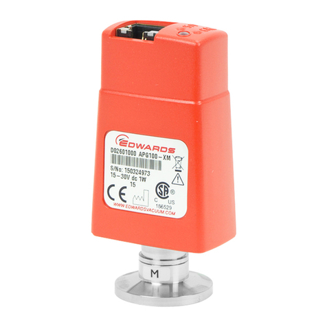
Edwards AIM-S-NW25 User manual

D146-41-880
Issue J
Instruction Manual
Active Inverted Magnetron Gauge
Description Item Number
AIM-S-NW25 D146-41-000
AIM-SL-NW25 D146-44-000
AIM-X-NW25 D146-42-000
AIM-XL-NW25 D146-45-000
Original instructions

This page has been intentionally left blank.
Declaration of Conformity
We, Edwards Limited,
Crawley Business Quarter,
Manor Royal,
Crawley,
West Sussex, RH10 9LW, UK
declare under our sole responsibility, as manufacturer and person within the EU authorised
to assemble the technical file, that the product(s)
xAIM-S-NW25 D146-41-000
xAIM-X-NW25 D146-42-000
xAIM-SL-NW25 D146-44-000
xAIM-XL-NW25 D146-45-000
to which this declaration relates is in conformity with the following standard(s) or other
normative document(s)
EN61010-1: 2010 Safety Requirements for Electrical Equipment for Measurement,
Control and Laboratory Use. General Requirements
EN61326-2-3: 2013 Electrical equipment for measurement, control and laboratory
(Class B Emissions Use. EMC requirements. Particular requirements. Test
Industrial Immunity) configuration, operational conditions and performance criteria
for transducers with integrated or remote signal conditioning
CAN/CSA-C22.2 Safety requirements for electrical equipment for measurement,
No.61010-1-04 Control and laboratory use – Part 1: General requirements
UL61010-1, 2nd Edition Safety requirements for electrical equipment for measurement,
Control and laboratory use – Part 1: General requirements
EN50581: 2012 Technical Documentation for the Assessment of Electrical and
Electronic Products with respect to the Restriction of Hazardous
Substances
and fulfils all the relevant provisions of
2014/35/EU Low Voltage Directive
2014/30/EU Electromagnetic Compatibility (EMC) Directive
2012/19/EU Waste Electrical and Electronic Equipment (WEEE) Directive
2011/65/EU Restriction of Certain Hazardous Substances (RoHS) Directive
Note: This declaration covers all product serial numbers from the date this Declaration was
signed onwards.
Larry Marini, Senior Technical Manager Date and Place
P200-02-600 Issue F
This product has been manufactured under a quality management system certified to ISO 9001:2008
19.08.2015, Eastbourne

© Edwards Limited 2015. All rights reserved. Page i
Edwards and the Edwards logo are trademarks of Edwards Limited.
Contents
D146-41-880 Issue J
Contents
Section Page
1 Introduction .......................................................................................1
1.1 Scope and definitions ................................................................................................... 1
1.2 Description ................................................................................................................ 1
1.3 Gas dependency .......................................................................................................... 2
2 Technical data ....................................................................................5
2.1 Mechanical data .......................................................................................................... 5
2.2 Performance, operating and storage conditions .................................................................... 5
2.3 Electrical data ............................................................................................................ 7
2.4 Error monitoring ......................................................................................................... 7
2.5 Materials exposed to vacuum .......................................................................................... 8
3 Installation .........................................................................................9
3.1 Unpack and inspect ...................................................................................................... 9
3.2 Fit the AIM Gauge to the vacuum system ............................................................................ 9
3.3 Electrical connections ................................................................................................... 9
3.3.1 Connect to Edwards controllers or AGD display ..................................................................... 9
3.3.2 Connect to your own supply and control equipment ............................................................... 9
4 Operation ........................................................................................ 13
4.1 Safety .....................................................................................................................13
4.2 Enable and disable the AIM Gauge ...................................................................................13
4.3 Pressure measurement .................................................................................................13
4.4 Set-point .................................................................................................................14
5 Maintenance ..................................................................................... 15
5.1 Introduction .............................................................................................................15
5.2 Replace the body tube .................................................................................................15
5.2.1 Remove the AIM Gauge from the vacuum system ..................................................................15
5.2.2 Fit the new body tube .................................................................................................15
5.2.3 Refit the AIM Gauge to the vacuum system ........................................................................15
5.3 Replace the electrode assembly ......................................................................................17
5.4 Replace the electronics and magnet housing ......................................................................17
5.5 Clean the internal components .......................................................................................17
5.6 Fault finding .............................................................................................................18
6 Storage and disposal ........................................................................... 19
6.1 Storage ...................................................................................................................19
6.2 Disposal ...................................................................................................................19
7 Spares and accessories ......................................................................... 21
7.1 Introduction .............................................................................................................21
7.2 Spares .....................................................................................................................21
7.3 Accessories ...............................................................................................................21
For return of equipment, complete the HS Forms at the end of this manual.
Xplanation 5717 03/2016

D146-41-880 Issue J
Page ii © Edwards Limited 2015. All rights reserved.
Edwards and the Edwards logo are trademarks of Edwards Limited.
Contents
Illustrations
Figure Page
1 General view of the AIM Gauge (showing the NW25 flange) ...................................................... 3
2 Dimensions (mm) ........................................................................................................ 6
3 Schematic diagram of typical electrical connections .............................................................10
4 Exploded view of the AIM Gauge .....................................................................................16

Tables
Table Page
1 Pins on the AIM Gauge electrical connector socket ...............................................................11
2 Pressure and voltage characteristics for nitrogen and dry air: AIM-S and AIM-SL Gauges ...................14

© Edwards Limited 2015. All rights reserved. Page 1
Edwards and the Edwards logo are trademarks of Edwards Limited.
Introduction
D146-41-880 Issue J
1Introduction
1.1 Scope and definitions
This manual provides installation, operation and maintenance instructions for the Edwards AIM Gauge (Active
Inverted Magnetron Gauge). You must use the AIM Gauge as specified in this manual.
Read this manual before you install and operate the AIM Gauge. Important safety information is highlighted as
WARNING and CAUTION instructions; you must obey these instructions. The use of WARNINGS and CAUTIONS is
defined below.
CAUTION
Cautions are given where failure to observe the instruction could result in damage to the equipment, associated
equipment or process.
The units used throughout this manual conform to the SI international system of units of measurement.
The following warning symbol also appears on the product:
1.2 Description
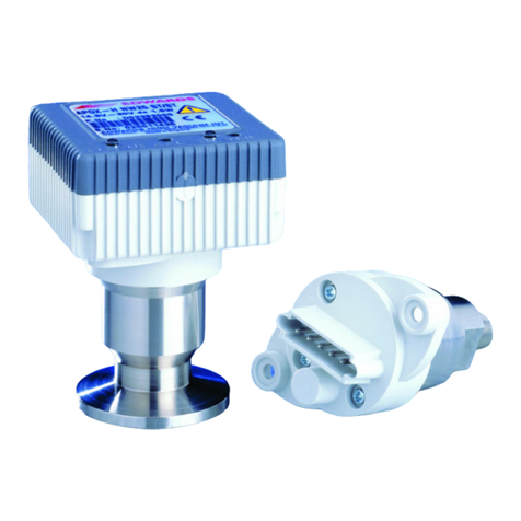
The AIM Gauge, shown in Figure 1, is an inverted magnetron gauge head and gauge controller in a single compact
unit. The gauge operates as a cold cathode ionisation gauge, in which the pressure is measured indirectly as a
function of the current which flows in a Townsend discharge maintained in the body tube.
Four versions of AIM Gauge are available; the ‘S’, ‘SL’, ‘X’ and ‘XL’ gauges. The ‘X’ and‘XL’ gauges have an extended
measurement range (see below) and a linear output characteristic. The ‘SL’ and ‘XL’ gauges have a very low external
magnetic field and are suitable for use with sensitive analytical instrumentation.
The measurement range of the AIM-S and AIM-SL gauges is 1 x 10⁻⁸ to 1 x 10⁻² mbar. The measurement range of the
AIM-X and AIM-XL gauges is 1 x 10⁻⁹ to 1 x 10⁻² mbar. The AIM gauge vacuum connection is an NW25 flange.
The AIM Gauge requires a 13.5 to 36 V d.c. power supply: it has a 2 to 10 V d.c. analogue output which is related to
pressure. The AIM Gauge is compatible with all of the Edwards AGCs (Active Gauge Controllers) and with the
appropriate versions of the Edwards AGDs (Active Gauge Displays).
Alternatively, you can use an independent power supply for the AIM Gauge and you can read the AIM Gauge output
signal with a voltmeter or an analogue-to-digital converter.
We recommend that you do not operate the AIM Gauge unless the pressure in the vacuum system is 1 x 10⁻² mbar or
lower. A gauge enable signal is used to control the operation of the AIM Gauge; refer to Section 4.2 for more
information.
An 8-way electrical connector socket on the AIM Gauge (Figure 1, item 6) is used to connect the AIM Gauge to your
AGC, AGD or electrical supply and voltmeter. Electrical cables fitted with suitable connector plugs are available
as accessories.
WARNING
Warnings are given where failure to observe the instruction could result in injury or death
to people.
Edwards will offer European customers a recycling service.

D146-41-880 Issue J
Page 2 © Edwards Limited 2015. All rights reserved.
Edwards and the Edwards logo are trademarks of Edwards Limited.
Introduction
A gauge identification signal is available on the electrical connector: this signal is used by Edwards AGCs to identify
which type of Active Gauge is connected.
The AIM Gauge has a set-point facility; the set-point signal is an open-drain transistor (FET) output, which is on when
the pressure measured by the Gauge is below a preset pressure. You can adjust the pressure at which the set-point
output goes on: refer to Section 4.4. Note that, if you use a Edwards AGC Controller or AGD Display, the AIM Gauge
set-point output signal is not used.
1.3 Gas dependency
The ionisation of the gas in the vacuum system is dependent on both the pressure and the physical properties of the
gas. Therefore, the output signal of the AIM Gauge is gas dependent.
The output signal voltage to pressure conversions in Table 2 apply for nitrogen and dry air.
Calibration graphs for use with argon, neon, krypton, helium and carbon dioxide are available on request; contact
your supplier or Edwards.

© Edwards Limited 2015. All rights reserved. Page 3
Edwards and the Edwards logo are trademarks of Edwards Limited.
Introduction
D146-41-880 Issue J
Figure 1 - General view of the AIM Gauge (showing the NW25 flange)
1. End-cap
2. Vacuum flange
3. Body tube
4. Magnet housing
5. Cable connector plug
6. Set-point potentiometer (on end of item 1)
7. AIM Gauge connector socket

D146-41-880 Issue J
Page 4 © Edwards Limited 2015. All rights reserved.
Edwards and the Edwards logo are trademarks of Edwards Limited.
This page has been intentionally left blank.

© Edwards Limited 2015. All rights reserved. Page 5
Edwards and the Edwards logo are trademarks of Edwards Limited.
Technical data
D146-41-880 Issue J
2Technicaldata
2.1 Mechanical data
2.2 Performance, operating and storage conditions
Dimensions See Figure 2
Mass
AIM-S/X-NW25 810 g
AIM-SL/XL-NW25 860 g
Volume of gauge tube 26 cm3
Enclosure rating IP40 (BS5490) and IP403 (IEC529)
Ambient temperature
operation 5 to 60 °C
storage 0 to 70 °C
Ambient humidity (operation) 10 to 90% (non-condensing)
Maximum operating altitude 2000 m
Indoor use only
Maximum internal pressure 10 bar absolute (9 bar gauge)
Pressure measurement range
AIM-S/SL-NW25 1 x 10⁻⁸ to 1 x 10⁻² mbar
AIM-X/XL-NW25 1 x 10⁻⁹ to 1 x 10⁻² mbar
Pollution degree 2

D146-41-880 Issue J
Page 6 © Edwards Limited 2015. All rights reserved.
Edwards and the Edwards logo are trademarks of Edwards Limited.
Technical data
Figure 2 - Dimensions (mm)
1. Clearance required for electrical cable

© Edwards Limited 2015. All rights reserved. Page 7
Edwards and the Edwards logo are trademarks of Edwards Limited.
Technical data
D146-41-880 Issue J
2.3 Electrical data
2.4 Error monitoring
The set-point output is switched off:
For 0.5 seconds during gauge switch-on
When pressure output signal voltage < 1.8 V.
Electrical supply
Voltage +13.5 to +36 V d.c.
Max voltage ripple 1 V peak to peak
Max source resistance 50 Ω
Maximum power consumption 2 W
Electrical connector FCC68/RJ45 type, 8-way
Pressure output signal
Range 2 < output < 10 V d.c.
Error range output < 2 V d.c. or output > 10 V d.c.
Impedance 0.1 Ω
Min load impedance 10 kΩ
Max current source 1 mA
Gauge enable
Control sense Active low
Active level < 1.3 V
Control impedance 12 kΩpull-up to positive supply
Set-point output external load rating 40 V d.c., 100 mA max
Set-point trip level
Range 1.8 to 10.0 V
Minimum load impedance 200 kΩ
Hysteresis 500 mV
Back EMF suppression diode *
*Required when you use an external d.c. Relay connected to the set-point output.
Min. surge rating 1 A
Min. reverse voltage rating 100 V
Gauge identification resistance
AIM-S/SL-NW25 100 kΩ+ 2%
AIM-X/XL-NW25 110 kΩ + 2%

D146-41-880 Issue J
Page 8 © Edwards Limited 2015. All rights reserved.
Edwards and the Edwards logo are trademarks of Edwards Limited.
Technical data
2.5 Materials exposed to vacuum
Stainless steel (AISI 304 and 306).
Fluoroelastomer.
Soda lime glass.

© Edwards Limited 2015. All rights reserved. Page 9
Edwards and the Edwards logo are trademarks of Edwards Limited.
Installation
D146-41-880 Issue J
3 Installation
3.1 Unpack and inspect
Remove all packing materials and protective covers and check the AIM Gauge.
If the AIM Gauge is damaged, notify your supplier and the carrier in writing within three days; state the Item Number
of the AIM Gauge together with your order number and your supplier’s invoice number. Retain all packing materials
for inspection. Do not use the AIM Gauge if it is damaged.
If the AIM Gauge is not to be used immediately, replace the protective covers. Store the AIM Gauge in suitable
conditions as described in Section 6.
3.2 Fit the AIM Gauge to the vacuum system
The AIM Gauge can be mounted in any orientation. To avoid the build-up of debris or condensable material in the
body tube of the AIM Gauge (which will probably cause pressure measurement errors), we recommend that you install
the AIM Gauge vertically as shown in Figure 2.
Use an ‘O’ ring/centring ring or Co-Seal and clamp to connect the NW25 flange of the AIM Gauge to a similar flange
on your vacuum system.
If required, you can turn the end-cap (relative to the magnet housing) so that the electrical connection socket is in
a convenient position on your system; refer to Figure 1 and use the following procedure: hold the magnet housing (4)
and turn the end-cap (1) in a clockwise or anticlockwise direction (arrow B) until the electrical connection socket (6)
is in the required position.
3.3 Electrical connections
When using a cable longer than 30 m, full compliance with European Standards requires an in-line surge suppressor
(please refer to Section 7.3)
3.3.1 Connect to Edwards controllers or AGD display
Connect the AIM Gauge to the controller or display with a cable which is terminated in suitable connectors. Suitable
cables are available from Edwards (refer to Section 7).
3.3.2 Connect to your own supply and control equipment
Note: Do not connect the electrical supply common (pin 2) to the signal common (pin 5). If you do, the AIM Gauge
pressure output signal will be inaccurate.
A schematic diagram of the recommended electrical connections to the AIM Gauge is shown in Figure 3.
The pins on the AIM Gauge electrical connection socket are used as shown in Table 1. The specification of the
electrical supply, d.c. relay and back EMF suppression diode are given in Section 2.
WARNING
If the AIM Gauge malfunctions, the AIM Gauge pressure output may be incorrect. If such a failure
could cause injury to people or damage equipment, you must install a suitable control system to
indicate the failure and, if necessary, to close down your process system.

D146-41-880 Issue J
Page 10 © Edwards Limited 2015. All rights reserved.
Edwards and the Edwards logo are trademarks of Edwards Limited.
Installation
Figure 3 - Schematic diagram of typical electrical connections
1. AIM Gauge electrical connector socket
2. Cable electrical connector plug
3. Electrical supply
4. Voltmeter (pressure signal)
5. D.C. relay (optional)
6. Back EMF suppression diode (optional)
7. Gauge enable switch
8. Voltmeter (set-point trip level)

© Edwards Limited 2015. All rights reserved. Page 11
Edwards and the Edwards logo are trademarks of Edwards Limited.
Installation
D146-41-880 Issue J
The connection to pin 6 is optional. Make the connection to pin 6 if you want to connect the set-point output signal
to a d.c. relay: you must connect a suppression diode between pins 1 and 6 to protect the AIM Gauge from transient
voltages generated when the d.c. relay is switched off.
You can connect a voltmeter between pins 5 and 8 to measure the set-point trip level (that is, the voltage at which
the set-point output will go on): see Figure 3.
Connect a switch betweenpins 2 and 7to enable and disable the gauge (refer to Section 4.2). If you want to measure
the gauge identification signal (which identifies the AIM Gauge), measure the resistance between pins 4 and 5.
Table 1 - Pins on the AIM Gauge electrical connector socket
Pin Number Use
1
2
3
4
5
6
7
8
Electrical supply positive voltage
Electrical supply common
Pressure measurement output signal
Gauge identification signal
Signal common
Set-point output signal
Gauge enable
Set-point trip level

D146-41-880 Issue J
Page 12 © Edwards Limited 2015. All rights reserved.
Edwards and the Edwards logo are trademarks of Edwards Limited.
This page has been intentionally left blank.

© Edwards Limited 2015. All rights reserved. Page 13
Edwards and the Edwards logo are trademarks of Edwards Limited.
Operation
D146-41-880 Issue J
4 Operation
4.1 Safety
4.2 Enable and disable the AIM Gauge
CAUTION
Do not operate the AIM Gauge for long periods when the system pressure is above 1 x10⁻² mbar. If you do, the
anode pin can be damaged and the AIM Gauge can be severely contaminated.
We recommend that you only enable the gauge when the system pressure is lower than 1 x 10⁻² mbar and that you
disable the gauge when the system pressure is 1 x 10⁻² mbar or higher.
If you have connected the AIM Gauge to an AGC or AGD, refer to the corresponding instruction manual for details of
how to enable (switch on) and disable (switch off) the AIM Gauge.
Otherwise, to enable (switch on) the AIM Gauge, connect pin 7 to pin 2 (or to ground). To disable (switch off) the AIM
Gauge, disconnect pin 7 from pin 2 (or from ground).
4.3 Pressure measurement
If you connected the AIM Gauge to a Edwards AGC controller or AGD display, the pressure measured by the AIM Gauge
is shown on the display.
If you connected the signal output of the AIM Gauge to a voltmeter, convert the measured voltage to the
corresponding pressure value: for AIM-S and AIM-SL gauges, refer to Table 2; for AIM-X and AIM-XL gauges, use the
equation:
P= 10
where Pis the pressure in mbar, and V is the measured voltage.
If necessary, adjust the pressure reading to compensate for the RMM of the gas in your vacuum system (refer
to Section 1.3).
WARNING
Do not use the AIM Gauge to measure the pressure of explosive or flammable gases or mixtures.
WARNING
Never operate the AIM Gauge when it is disconnected from the vacuum system or when there are
explosive or flammable gases in the surrounding atmosphere or the vacuum system. High voltages
(up to 3 kV) are generated inside the body tube of the AIM Gauge; these could cause injury to
people or could be a source of ignition.
WARNING
The AIM Gauge incorporates magnets. Keep away from Heart Pacemakers, Computers, Credit Cards
and any other magnetically sensitive devices.
(7/8V - 10.75)

D146-41-880 Issue J
Page 14 © Edwards Limited 2015. All rights reserved.
Edwards and the Edwards logo are trademarks of Edwards Limited.
Operation
4.4 Set-point
Note: The set-point is not used if you connect the AIM Gauge to a Edwards AGC Controller or AGD Display.
To adjust the voltage at which the set-point output signal goes on, turn the set-point potentiometer, which is
accessible through an access hole in the end-cap of the gauge: see Figure 1. Turn the potentiometer clockwise to
increase the voltage and turn it anticlockwise to decrease the voltage. Refer to Section 4.3 to determine the
operating voltage which corresponds to a given pressure.
The AIM Gauge has an error monitoring facility, which ensures that the set-point output signal is off:
When the Gauge is switched off (that is, not enabled).
For 0.5 seconds immediately after the AIM Gauge is switched on.
When the pressure output signal is out of range, perhaps because the gauge has failed to strike (ignite).
If required, you can adjust the potentiometer so that the set-point operating voltage is < 1.8 V (that is, turn the
potentiometer fully anticlockwise). This ensures that the set-point output signal is permanently off.
If required, you can use the set-point output signal to indicate when the Gauge is operating correctly: adjust the
potentiometer so that the set-point operating voltage is > 10 V (that is, turn the potentiometer fully clockwise). If the
Gauge is operating normally, the set-point output signal will then be switched on.
Note: If you adjust the set-point operating voltage to > 9.5 V, the hysteresis voltage will be > 10 V and the
set-point output signal may not switch off when the pressure rises; if so, the set-point output signal will
only go off when the gauge is switched off (that is, disabled).
Table 2 - Pressure and voltage characteristics for nitrogen and dry air: AIM-S and AIM-SL Gauges
Pressure (mbar) Output voltage
(V) Pressure (torr) Pressure (mbar) Output voltage
(V) Pressure (torr)
1.0 x 10⁻⁸
2.4 x 10⁻⁸
5.8 x 10⁻⁸
8.1 x 10⁻⁸
1.1 x 10⁻⁷
1.5 x 10⁻⁷
2.1 x 10⁻⁷
2.9 x 10⁻⁷
4.0 x 10⁻⁷
5.4 x 10⁻⁷
7.3 x 10⁻⁷
9.8 x 10⁻⁷
1.3 x 10⁻⁶
1.7 x 10⁻⁶
2.2 x 10⁻⁶
2.8 x 10⁻⁶
3.6 x 10⁻⁶
4.5 x 10⁻⁶
5.6 x 10⁻⁶
2.00
2.50
3.00
3.20
3.40
3.60
3.80
4.00
4.20
4.40
4.60
4.80
5.00
5.20
5.40
5.60
5.80
6.00
6.20
7.5 x 10⁻⁹
1.8 x 10⁻⁸
4.4 x 10⁻⁸
6.1 x 10⁻⁸
8.3 x 10⁻⁸
1.1 x 10⁻⁷
1.6 x 10⁻⁷
2.2 x 10⁻⁷
3.0 x 10⁻⁷
4.1 x 10⁻⁷
5.5 x 10⁻⁷
7.4 x 10⁻⁷
9.8 x 10⁻⁷
1.3 x 10⁻⁶
1.7 x 10⁻⁶
2.1 x 10⁻⁶
2.7 x 10⁻⁶
3.4 x 10⁻⁶
4.2 x 10⁻⁶
6.9 x 10⁻⁶
8.4 x 10⁻⁶
1.0 x 10⁻⁵
1.2 x 10⁻⁵
1.4 x 10⁻⁵
1.7 x 10⁻⁵
2.0 x 10⁻⁵
2.4 x 10⁻⁵
2.9 x 10⁻⁵
3.5 x 10⁻⁵
4.3 x 10⁻⁵
5.7 x 10⁻⁵
7.9 x 10⁻⁵
1.2 x 10⁻⁴
1.9 x 10⁻⁴
3.3 x 10⁻⁴
6.7 x 10⁻⁴
1.7 x 10⁻³
3.6 x 10⁻³
1.0 x 10⁻²
6.40
6.60
6.80
7.00
7.20
7.40
7.60
7.80
8.00
8.20
8.40
8.60
8.80
9.00
9.20
9.40
9.60
9.80
9.90
10.00
5.2 x 10⁻⁶
6.3 x 10⁻⁶
7.5 x 10⁻⁶
9.0 x 10⁻⁶
1.1 x 10⁻⁵
1.3 x 10⁻⁵
1.5 x 10⁻⁵
1.8 x 10⁻⁵
2.2 x 10⁻⁵
2.6 x 10⁻⁵
3.2 x 10⁻⁵
4.3 x 10⁻⁵
5.9 x 10⁻⁵
9.0 x 10⁻⁵
1.4 x 10⁻⁴
2.5 x 10⁻⁴
5.0 x 10⁻⁴
1.3 x 10⁻³
2.7 x 10⁻³
7.5 x 10⁻³

© Edwards Limited 2015. All rights reserved. Page 15
Edwards and the Edwards logo are trademarks of Edwards Limited.
Maintenance
D146-41-880 Issue J
5Maintenance
5.1 Introduction
The internal components of the AIM Gauge are shown in Figure 4. The AIM Gauge is designed so that you can easily
clean these components, or use the spares listed in Section 7 to replace these components. Refer to the following
sections for details of the maintenance procedures, which you should do when necessary.
5.2 Replace the body tube
Refer to Figure 4 and use the following procedures to replace the body tube:
5.2.1 Remove the AIM Gauge from the vacuum system
1. Switch off the AIM Gauge electrical supply and ensure that the vacuum system is at atmospheric pressure.
2. Disconnect the cable connector plug (Figure 1, item 5) from the AIM Gauge and remove the AIM Gauge from the
vacuum system.
5.2.2 Fit the new body tube
1. Hold the magnet housing (1) and turn the body tube (5) anticlockwise (when viewed from the vacuum flange) to
unlock the bayonet fitting. Remove the body tube from the magnet housing.
2. Slide the new body tube into the magnet housing (1) (as shown by arrow B).
3. Hold the magnet housing (1) and turn the body tube (5) clockwise (when viewed from the vacuum flange) to lock
the bayonet fitting (as shown by arrow C).
5.2.3 Refit the AIM Gauge to the vacuum system
Refit the AIM Gauge to the vacuum system as described in Section 3.2 and refit the cable connector plug to the socket
on the AIM Gauge (Figure 1, item 6).
WARNING
Do not disconnect the electronics and magnet housing from the body tube when the body tube is
connected to the vacuum system. If there is a plasma discharge in the vacuum system near the
body tube, the body tube can become electrically charged.
WARNING
Disconnect the cable from the AIM Gauge before you remove the AIM Gauge from the vacuum
system. High voltages are generated inside the AIM Gauge.

D146-41-880 Issue J
Page 16 © Edwards Limited 2015. All rights reserved.
Edwards and the Edwards logo are trademarks of Edwards Limited.
Maintenance
Figure 4 - Exploded view of the AIM Gauge
1. Magnet housing
2. Collar
3. Anode assembly
4. ‘O’ ring
5. Body tube
6. Cathode plate
7. Cathode tube
8. Circlip
Other manuals for AIM-S-NW25
3
This manual suits for next models
3
Table of contents
Other Edwards Measuring Instrument manuals

Edwards
Edwards AIM-S-NW25 User manual

Edwards
Edwards PRG20K User manual

Edwards
Edwards AIM-SI1-NW25 User manual

Edwards
Edwards GXS 0-60 SLM User manual

Edwards
Edwards TruWave User manual

Edwards
Edwards Barocel 7045 User manual

Edwards
Edwards M528-09-160 User manual

Edwards
Edwards OLM100 User manual

Edwards
Edwards FSRZI-A Assembly instructions

Edwards
Edwards AIM-S-NW25 User manual