Pro-Cut PFM 9.2 DRO User manual

TECHNICAL MANUAL


PG / ØØ4 800.543.6618
OUR MISSION
Pro-Cut International is dedicated to providing our customers with the most advanced, pre-
cise, and profitable tools for brake repair. We have worked with, learned from and solved
problems for people at all levels of the brake repair business - from the largest auto manufac-
turers and national service chains to one-bay, one-man operations. It is a business our entire
staff lives, eats, and breathes. We welcome you to our table and look forward to working with
you to improve your brake service business.

WWW.PROCUTUSA.COM PG / ØØ5
What Your Warranty Does Not Cover
This warranty does not apply to damage due directly to misuse, abuse, negligence or lack of maintenance.
Limited Warranty
This warranty extends to the original owner of the the equipment. Pro-Cut International warranties this
equipment against defects in materials or workmanship as follows.
Labor
For the period of one (1) year from the original date of purchase, if we determine that the equipment is
defective subject to the limitations of this warranty, we will replace it at not charge for labor. Pro-Cut
International warrants any such work done against defects in materials or workmanship for the remaining
portion of the original warranty period.
Parts
For the period of one (1) year from the original date of purchase, we will supply, at no charge, new or
rebuilt replacement parts in exchange for parts we determine are defective subject to the limitations of
this warranty. Pro-Cut International warranties any such replacement parts against defects in materials or
workmanship for the remaining portion of the original warranty period.

PG / ØØ6 800.543.6618
CONTENTS
4 Pro-Cut Mission
7 Safety and Warning Information
8 Introduction
10 Lateral Run-out Defined
12 9.2 DRO Lathe Overview
14 Lathe Setup
16 Vehicle Preparation
18 Lathe Preparation: Checking Cutting Tips
19 Machining Rotors: A 4 Step Guide
Step 1: Mount the Adapter
Step 2: Set Up the Lathe
Step 3: Adjust for Lateral Run-out
Step 4: Make the Cut
27 Machining the Opposite Side
28 Vehicle Reassembly
29 Maintenance
30 Troubleshooting: Assuring a Smooth Finish
33 Troubleshooting: Lateral Run-out Adjustment
34 Troubleshooting: Raising or Lowering the Acceptance Number
36 DRO Compensation Instructions
40 G2X Technical Supplement
42 G2X Component Overview
44 50-1250 Cutting Head
47 50-1206 Slide Sensor
48 50-1148 Gage Pick Up Module
50 G2X Calibration
53 G2X Troubleshooting
54 GYR Technical Supplement
56 GYR Component Overview
58 Setting up your GYR
60 GYR Service Corridor Concept
67 Customer Vehicle and Management Reports
69 GYR Troubleshooting
72 Adapter Guide
74-86 9.2 DRO Parts Diagrams
88 Maintenance Schedule
9.2 DRO Lathe Body
50-220 Cutting Head
50-139 Bevel Gear Box
50-2193 Trolley
50-1148 Gage Pick Up Module
50-1162 Computer Box
50-1250 Cutting Head
50-1206 Slide Sensor
50-1740 Spindle Guard
50-143 Slide Assembly
50-1360 GYR Command Center
50-1902 Motor and Gear Box Assembly

WWW.PROCUTUSA.COM PG / ØØ7
IMPORTANT SAFETY INSTRUCTIONS
The 9.2 DRO Rotor Matching System is a precision instrument which requires close attention while in operation. It will
provide many years of service if it is operated safely. Basic Safety precautions should always be followed, including
the following:
Read all instructions
Care must be taken as burns can occur from touching hot parts.
Do not operate equipment with a damaged cord or if the equipment has been dropped or damaged - until it has been
examined by a qualified service person.
Do not let a cord hang over the edge of the table, bench, counter or come in contact with hot manifolds or moving fan
blades.
If an extension cord is necessary, a cord with a current rating equal to or more than that of the equipment should be
used. Cords rated for less current than the equipment may overheat. Care should be taken to arrange the cord so that
it will not be tripped over or pulled
Always unplug equipment from electrical outlets when not in use. Never use the cord to pull the plug from the outlet.
Grasp the plug and pull to disconnect.
Let equipment cool completely before putting away. Loop cord loosely around equipment when storing.
To reduce the risk of fire, do not operate equipment in the vicinity of open containers of flammable liquids (gasoline).
Adequate ventilation should be provided when working on operating internal combustion engines.
Keep hair, loose clothing, fingers, and all parts of the body away from moving parts.
To reduce the risk of electric shock, do not use on wet surfaces or expose to rain.
Use only as described in this manual. Use only manufacturer’s recommended attachments.
ALWAYS WEAR SAFETY GLASSES. Everyday eyeglasses only have impact resistant lenses. THEY ARE NOT SAFETY
GLASSES.
1.
2.
3.
4.
5.
6.
7.
8.
9.
10.
11.
12.
13.
SAVE THESE INSTRUCTIONS

PG / ØØ8 800.543.6618
Congratulations on your purchase of the PRO-CUT 9.2 DRO, the world’s fastest and most accurate computer-
ized on-car brake lathe.
For many years, on-car lathes were used only for rotors that were difficult to remove. Due to current trends,
virtually all auto manufacturers now require or recommend the use of on-car technology to match every rotor
to every hub. By matching a rotor to the hub, the chance of a vehicle returning for a lateral run-out induced
brake pedal pulsation is virtually eliminated. There is simply no better way to refinish and match a rotor than
with the patented ROTOR MATCHING SYSTEM.
The following pages are designed to guide you through set-up, operation, and maintenance of your lathe. We
recommend that technicians take the online training in our TrainSmart section of the website:
http://www.procutusa.com/trainsmart.aspx
If you have any questions along the way, please call us. Our technical support team is standing by from 8
a.m. to 5 p.m. Eastern time. Or browse our website for technical information and tips: www.procutusa.com
WELCOME TO THE PRO-CUT TEAM.
INTRODUCTION

WWW.PROCUTUSA.COM PG / ØØ9
Every Pro-Cut 9.2 DRO lathe comes with setup and training included by a local, certified Pro-Cut Rep. Please
contact Pro-Cut at 800-543-6618 immediately if you have not already made arrangements for on-site training.
Every 9.2 DRO lathe also comes with the ability to be packaged as a stand alone service called BrakeSaver. Please
contact Pro-Cut to receive your BrakeSaver point of sale marketing kit. Your local Pro-Cut Rep can help you launch
the new service at the time of lathe set up and training, and Pro-Cut will promote your shop on our website as a
certified BrakeSaver location. Now that you have the the best way to perform brake rotor service, why not promote
that fact and add dollars to your bottom line while giving your customers the best brake job on the planet!
Adapter Packages
50-380
50-220
50-046
50-703
50-754
50-752
4 to 8 adapter packages
Adjustable Disc-Lock Trolley
Speed-Lock Cutting Head
Nose Cone Extension
Disc Silencer
Double-Thick Disc Silencer
Lathe Cover
50-246
30-791
50-179
50-742
50-660
(2)37-034
50-729
Small Spacer
Large Spacer
Nut & Bolt Kit
Premium Pro-Cut Cutting Tips (10pcs.)
Tool Box Complete
S-Hooks
Brake Specification Guide
YOUR LATHE PACKAGE Getting the Most From Your New Rotor Matching System

PG / Ø1Ø 800.543.6618
LATERAL Run-out leads to ...
THICKNESS VARIATION which results in ...
BRAKE PEDAL PULSATION.
Run-out DEFINED
WWW.PROCUTUSA.COM PG / Ø11
Brake pedal pulsation is most often the result of thickness variation in the brake
rotor. Thickness variation is the technical term for a rotor that is not uniformly
thick. New rotors are uniformly thick, and stop the vehicle smoothly. But thick-
ness variation can develop over time and eventually lead to brake pedal pulsa-
tion.
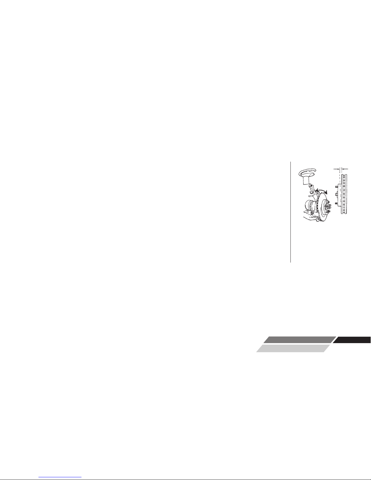
How does thickness variation develop? Through lateral run-out in the face of the
rotor. Lateral run-out is the technical term for “wobble”, and is a measurement of
how much the surface of the disc wobbles from side to side as it rotates .
A rotor with lateral run-out will not wear evenly, and uneven wear increases over
time. As the vehicle moves down the road with the brakes relaxed, the rotor will
brush each pad once per revolution, resulting in a thin spot on the rotor.
Since vehicle hubs often have lateral run-out due to stacked component toleranc-
es, a new or newly machined rotor will often exhibit excessive lateral run-out as it
turns on the hub. Most manufacturers require rotor run-out to be below 0.002”.
The 9.2DRO Rotor Matching System allows you to match every rotor to the hub on
which it turns. The on-board computer delivers a precise alignment between the
lathe axis and the hub axis, thereby guaranteeing that a Pro-Cut machined rotor
will have less than 0.001” lateral run-out every time.
By match-machining the
rotor to the hub assembly
on which it resides, lateral
run-out will be reduced to
below OEM specs every
time!
PG /Ø11
WWW.PROCUTUSA.COM

PG / Ø12 800.543.6618
Lathe Overview
1
2
5
3
13
12
9
8
15
10
11
7
14
4
*Guard 50-1730 Not Shown
16
6

WWW.PROCUTUSA.COM PG / Ø13
1. 9.2DRO Computer Box
2. On/Off Switch
3. 1 hp Motor
4. Draw Bar Knob
5. Adjustment Flange (obscured)
6. Adjustment Solenoid (obscured)
7. Feed Engagement Knob (obscured)
8. Disc-Lock Lever
9. Automatic Shut-off Switch
10. Automatic Shut-off Cam
11. Cut Depth Adjustment Dials
12. Cutting Tips/Inserts
13. Tool Arm Lock Lever
14. Cutting Head lateral Lock Lever
15. Trolley (optional model 50-2192 shown)
16. Height Adjustment
NOTE* 50-1730 GUARD NOT SHOWN
COMPONENTS

PG / Ø14 800.543.6618
Before you begin setting up, check contents
against the parts diagram enclosed in the
lathe package. If you are missing any parts,
call Pro-Cut immediately.
SETTING UP A NEW LATHE

WWW.PROCUTUSA.COM PG / Ø15
ASSEMBLE THE TROLLEY
Open the trolley box and check contents against the parts diagram . If you are missing any parts, call Pro-Cut
immediately. Proceed with assembly, following the instructions enclosed in the box.
MOUNT THE LATHE TO THE TROLLEY
Once the trolley is assembled you will need to mount the lathe to the trolley. Locate lathe arm on trolley so
that lathe will be in upright horizontal position when it is installed, then lock the disc-lock lever firmly.
1 ) Remove the lathe body from the shipping pallet and install mounting studs under lathe in two threaded
holes the pallet bolts were removed from.
2 ) Find another person to help lift the lathe using the handles on either end, and insert the lathe mounting
studs into trolley arm. Secure with two nuts (36-001B) and flat washers (37-108).
3 ) Assemble Guard to Lathe if so equipped. See Page 48 for assembly drawing of Guard 50-1730.
Guard 50-1730 is mandatory in the Province of Quebec.
Assemble the trolley com-
pletely then get assis-
tance from another person
to mount the lathe on the
trolley.
Cutting
Edge
Tip

PG / Ø16 800.543.6618
VEHICLE PREPARATION
Before lifting the vehicle, the front wheels should be straight and the parking brake should be off, with the
transmission in neutral.
NOTE: Remember to index mark rotors before removing them so you
can be sure they are returned to the same positions on the hub.
1. Raise the vehicle according to the lift manufacturer’s instructions. Raise until the wheel hub is about belt level.
2. Check wheel bearings for damage or excessive play. If this or any other wheel service is required, it should be performed
before match-machining the rotors as loose or damaged bearings will keep the lathe from doing the most accurate job possible.
3. Remove the wheels. Remove the brake calipers and suspend them out of the way of moving parts such as half shafts and
CV joints using the yellow S-hooks provided (pn 37-034K). Be sure to remove all wheels that may turn when the lathe is
turned on.
4. If the rotor is free on the hub, mark and remove it in order to assess the mating surface. Use a ScotchBrite™type wheel
on a die grinder, or other suitable wheel hub cleaning tool to remove rust or debris. Clean all material from the mounting
area.
5. The rotor on the side of the wheel that is not to be machined should be marked and removed if it is free on the hub or
secured with at least 2 lug nuts. Match marking the rotors to the hub is very important.
6. Use a micrometer to measure rotor thickness and determine how much material may be removed from the rotor by com-
paring to brake spec guide provided. Visually inspect for deep rust or grooves. This inspection will help determine the
depth of the cut.

WWW.PROCUTUSA.COM PG / Ø17
It is important to start on the proper side. The Pro-Cut mounts directly to the hub of the vehicle.
With the lathe right-side up (FIG:1) the cutting head is to the right of the hub as you face the vehicle
wheel well. When machining a rotor, the cutting head is most often positioned where the caliper
rides. On a vehicle where the calipers ride in front of the hub, always start on the passenger side. If
the caliper rides to the rear of the hub, begin on the driver’s side.
When you flip the lathe to machine the opposite side of the vehicle (FIG:2), no lateral cutting head
adjustments are required since they were made in the upright position.
Lathe in upside-down position. You will need to flip the
lathe over into this position to machine one side of the ve-
hicle if there is a dust shield, or other interference behind
the rotor.
The Pro-Cut 9.2DRO
machines both front
and rear rotors. The
lathe’s operations do
not change at all in the
rear of the vehicle.
NOTE
Lathe in upright position. Note that adjustments to cut-
ting head are simpler in this position.
FIG:1
FIG:2

PG / Ø18 800.543.6618
LATHE PREPARATION
This is the premium Pro-
Cut tip (50-742).When
the tip is mounted cor-
rectly, the chip breaker
and dots face up.
Before mounting the lathe, check the cutting tips and make sure they are ready for use. The cutting tips are one of the most
critical components of the machine. It is vital that they are Pro-Cut brand tips in good condition and properly mounted. Each
cutting tip has three corners which may be used. The correctly installed tip is wider on the top and has a groove, or dots, fac-
ing up. A tip mounted upside down will produce a surface finish that looks like a record.
You should get at least 7 cuts per corner. However, tip life is affected by variables such as rust or ridges. In order to deter-
mine when to rotate tips, monitor rotor finish. If the rotor finish begins to look inconsistent, or feels rough to the touch, tips
should be rotated. Tips that are chipped or cracked should never be used.
Be sure that the tip pocket is clean before positioning the tip. Any foreign material pinched under the tip will cause problems.
NOTE 2: Use only Pro-Cut Cutting Tips (50-742). Although other tips may
fit the machine, only Pro-Cut tips have been specifically engineered in tan-
dem with the Pro-Cut lathe. Using a non-Pro-Cut tip may compromise lathe
performance and result in poor surface finish.
NOTE 1: The lathe has a powerful 1 hp motor which requires 20 amp ser-
vice. All extension cords must be at least 12 gauge and less than 25 feet;
drop light cords are not recommended.
CHECK CUTTING TIPS

WWW.PROCUTUSA.COM PG / Ø19
The adapters are made of
case iron, not aluminum or
steel like wheels. They are
not designed to withstand
the use of impact tools.
DO NOT USE IMPACT
GUNS TO ATTACH THESE
ADAPTERS! Twenty to
thirty ft.-lbs. applied by
hand is plenty to secure
the adapter to the vehicle.
Excess torque applied
with an impact wrench
will damage the adapters.
Warranty does not cover
this misuse.
WARNING
STEP 1: MOUNT THE ADAPTER (2 Minutes)
MACHINING ROTORS
In just 4 steps in about 7-9 minutes, any tech can perform top-quality brake work.
Step 1: Mount the Adapter (2 mins.)
Step 2: Set up the Lathe (1-2 mins.)
Step 3: Adjust for Lateral Run-out (1 mins.)
Step 4: Make the Cut (3-4 mins.)
The First step is to choose the proper adapter. Most passenger cars require either the four (50-687) or
five lug (50-688) Direct Fit® adapter. Some larger passenger cars and smaller trucks use the (50-695)
adapter. For most trucks and vans, use the larger adapter (50-691) or the Asian / European variant, the
50-681. This fits 5, 6, 7, and 8-lug vehicles. See the adapter guide on pages 72-73 of this manual, or
use the adapter search on the Pro-Cut website for more specific information.
Once you’ve selected the correct size adapter, try each bolt pattern until you find the one that fits the ve-
hicle evenly. When possible, use the nuts provided with the machine. Hand tighten nuts with an open
box end wrench or a torque wrench in a star pattern. Do not use impact wrenches to mount adapters.
Nuts should be hand-tightened to 25-30 ft. lbs. Excess torque may damage the adapter.
Some vehicles require the use of a spacer (30-791 or 50-246) which are provided in the lathe package.
If the adapter doesn’t fit flush and square, use the spacer. Sometimes the holes in the spacer are not
needed as the entire bolt pattern will fit in the center of the spacer.
If the four steps are followed properly on each brake job, the Pro-Cut 9.2DRO RMS will operate accurately and efficiently.

PG / Ø2Ø
MACHINING ROTORS CONTINUED
Vibration is the root cause of
most surface finish problems.
Be sure the cutting head is
securely locked in place.
Tight connections here reduce
the chance of vibration.
SECURING THE
CUTTING HEAD
STEP 2: SET UP THE LATHE (2 Minutes)
A. Mount the Lathe to the Adapter
Move the cutting head out so that the tips will not strike the rotor as you mount the lathe.
Next, roll the machine into place and match it up with the adapter. Note that the trolley moves up
and down to accommodate different heights. The small dowel pin on the face of the adapter will fit
into either of several holes on the run-out adjustment flange. Turn the draw bar knob to thread into
the adapter securely connecting the lathe to the vehicle.
NOTE: It is very important that the machine be mounted smoothly on the adapter without prying or
forcing. Take the time to align the machine properly in order to avoid damage to the run-out adjust-
ment flange. The large draw bar knob will spin on very easily when the machine is properly aligned,
much like installing an oil filter. Tighten it by hand only.
Loosen the trolley handle so that the machine is free to rotate. Rotate the machine so that the cutting
head is in a position where there is clearance to make the cut. Be sure to check the back side of the
rotor for obstacles. Make sure there will be clearance for the chip deflector as well. Lock the trolley
lever securely so the machine will not rotate when the motor is started.
B. Position the Lathe for Cutting
Table of contents
Other Pro-Cut Lathe manuals


Popular Lathe manuals by other brands


Harbor Freight Tools
Harbor Freight Tools 31316 user manual

Laguna Tools
Laguna Tools Revo 10x16 Mini manual

Clarke
Clarke WOODWORKER CWL1000CF Operation & maintenance instructions

Grizzly
Grizzly T10811 instructions

Huvema
Huvema HU 410 x 800 VAC TOPLINE instruction manual

Woodtec
Woodtec XW074 instruction manual

Gude
Gude GMH 2000 Translation of the original instructions

Acra
Acra 1440GWI Operation manual

EINHELL
EINHELL BT-WW 1000 Original instruction manual

Jet
Jet E-1440VS Operating instructions and parts manual

Teknatool
Teknatool NOVA Comet II Instructions and parts manual

Optimum
Optimum OPTiturn TM 4010 operating manual