Ergon Crafco Patcher I Diesel User manual

Patcher I Diesel
PART MANUAL - 56933
Rev. 0

2
Revised: 02/06

3
Patcher I Diesel
Part Number 56900 (Skid Mount)

4
TABLE OF CONTENTS
PatcherI............................................................................................................................... 5
SafetyPrecautions...............................................................................................................6-7
LimitedWarranty.................................................................................................................. 8
WarrantyClaimInstructions.................................................................................................9
Specifications.......................................................................................................................10
Introduction............................................................................................................................11
OperatingInstructions
MachineStartUp..........................................................................................12
Figures1and2............................................................................................ 13
Figures3and4............................................................................................ 14
Figures5and6............................................................................................ 15
Figures7and8............................................................................................ 16
Caution..........................................................................................................17
ShutdownProcedure................................................................................... 17
StoringMachine........................................................................................... 17
TroubleShootingChart............................................................................... 18
ServiceInstructions..................................................................................... 18
Maintenance MaintenanceInstructions............................................................................ 19
MaintenanceChart...................................................................................... 20
RecommendedFluids&Lubricants.......................................................... 21
TypicalSpecifications..................................................................................21
GeneralMaintenanceItems........................................................................ 22
InstructionsforOrdering Parts.................................................................... 22
PatchingMaterialPlacement......................................................................23
ApplicationSteps.........................................................................................23
ApplicationofthePatchingProduct........................................................ 24
BurnerTroubleShooting..............................................................................25
DieselBurnerElectrodeAdjustment..........................................................26
DieselBurnerSettings.................................................................................26
RTDSensor-Ohmsvs.Temperature........................................................27
Parts PatcherIDiagramsandParts....................................................................28-32
PlaceforNoted.............................................................................................33
HydraulicDiagramandParts..................................................................... 34-36
5
Patcher I Diesel
Thismanualisfurnishedwitheachnew CRAFCO Patcher I Diesel MIXER. Themanual will
helpyour machine operatorslearntorunthe mixer properly andunderstanditsmechanical
functionsfor trouble-freeoperation.
Your CRAFCO Patcher I Diesel MIXER is designed to give excellent service and save
maintenanceexpense. However,aswith all specifically engineered equipment, youcanget
bestresultsatminimumcostsif:
1. Youoperateyourmachine as instructedinthismanual, and
2. Maintainyourmachine regularly asstatedinthis manual.
WARNING: The engine exhaust from this product containschemicals
known to theStateof California to cause cancer, birth defectsor other
reproductiveharm. Operate in well ventilatedareaonly. Engineexhaust
isdeadly.

6
SAFETY PRECAUTIONS
•Highoperatingtemperatures of product and machine require protective clothing, long sleeve
shirt,long pants/coveralls, hat or hard hat (ifrequired)andflameresistantglovesbe worn by
operator.
•Alwaysweareyeprotection (goggles or faceshield) when operating hotcompressedair
lance,airgaslance and when applying material. Faceshield is tobeworn when adding mate-
rialto the Patcher I.
•Observe all CAUTIONAND WARNING signs posted on machine.
•Avoidthe entrance of water into any partofthemachine. Water will displace heat transferoil
ormelted material when it reaches operating temperatures which could be hazardous to
personnelsurroundingthemachine.
•Avoidbodily contactwith hot applied patchingmaterial or heat transfer oil;seriousburnsmay
result.
•ReadOperatorManualthoroughlybeforeoperatingmachine.
•Makesure operator is familiar with machine operation.
•Do not operate in closed building or confined areas.
•Shut-downburner and engine prior to refilling diesel tank.
•When adding material to material tank, stop mixer, lift lid, add material and close lid before
restartingmixer. Hotmaterial could splashandcauseseriousburnsifthis procedure is not
followed.
•Keephands,feet,andclothingaway from all moving parts.
•Alwayskeepafireextinguisherneartheunit. Maintainextinguisher properly and be familiar
withits use.
•Donotexceed525OF. for heat transfer oil temperature.
•Donot overfill heat transfer oil level. Expansionofoilduringheatupcouldcause overflow.
Check oil each day before starting burner, add oil to touch bottom of dipstick if required (at
70OF.) Useonly recommended heat transfer oil and change after500hoursof operation or
oneyear,whicheveroccursfirst.

7
SAFETY PRECAUTIONS continued
•Followoperating instructions forstartingandshut-downofburner. Instructionsaremounted
oncontrolbox.
•Replaceanyhoseswhichshowsignsofwear,fraying, or splitting. Be sure all fittings and
jointsare tight and leak-proof.
•Precautionisthebest insurance against accidents.
•ThePatcher I mixershouldnot be leftunattendedwithburner lit.
•Tightenallboltsandscrewsafterevery100hoursofoperation.
•Crafco,Inc. assumesnoliabilityforanaccidentor injury incurred through improper use of the
machine.

8
Patcher I Diesel
LIMITED WARRANTY
Crafco,Inc., through itsauthorized distributor,will replace for the original purchaserfreeof
chargeany partsfounduponexaminationbythefactory at Mesa,Arizona, to bedefectivein
materialorworkmanship. Thiswarrantyis for a period within 60 days of purchase date, but
excludesengineorcomponents,tires,andbatteryastheseitemsaresubjecttowarranties
issuedby theirmanufacturers.
After60 days,Crafco,Inc.warrants structuralparts,excludingheating system,hydrauliccom-
ponents,and electrical componentsfor a periodofone(1) year from date of delivery. Crafco,
Inc.,shallnot be liable for parts that have been damaged by accident, alteration, abuse, im-
properlubrication/maintenance, normal wear,orothercausebeyondour control.
Thewarranty provided herein extends onlytotherepairand/orreplacement of those compo-
nentsontheequipmentcoveredaboveanddoesnotcover labor costs. The warranty does
notextendtoincidentalorconsequentialdamagesincurredasaresultofanydefectcovered
bythiswarranty.
Alltransportationandlaborcostsincurred by the purchaser in submitting or repairing covered
componentsmust be incurredbythepurchaser.
Crafco,Inc. specifically disavows any otherrepresentation,warranty, or liabilityrelatedtothe
conditionoruseof the product.
WARNING: Useofreplacement parts other than genuine Crafcoparts
mayimpair the safety orreliabilityofyourequipment and nullifies anywarranty.

9
WARRANTY CLAIM INSTRUCTIONS
Pleasefollow the instructions statedbelowwhencallingin a WarrantyClaim. Failuretofollow
theseprocedures may be cause to void the warranty.
1. Callyour local Crafco Distributor. Ifyoudonot know who your local distributor is, call
aCrafcoCustomerServiceRepresentative,(tollfree 1-800-528-8242) for name,
location,andtelephonenumber.
2. OncontactingtheDistributor,be preparedtoidentifythe machine type, model number,
andserialnumber,also the date of purchase if available.
3. Shouldthecauseofthemalfunction be a defective part, the Distributor will advise you
oftheprocedure to follow for a replacement.
4. Thewarrantyis valid only for parts which havebeensuppliedorrecommendedby
Crafco,Inc.
Ifyou have any additional questions regarding warranty repairs and parts, please do not
hesitatetocalltoll free 1-800-528-8242.
CRAFCO,INC.
235SOUTH HIBBERT
MESA, AZ 85210
480-655-8333
480-655-1712 (FAX)
TollFree 1-800-528-8242

10
SPECIFICATIONS
VatCapacity............................................................. 95 gallons
HeatTransferOilRequired..................................... 17 gallons at 70OF.
TankConstruction.................................................... Double boiler type
TankOpeningSize(2)............................................. 14.25” x 17.88” (each)
MaximumHeatInput.................................................260,000B.T.U.
Burner&TemperatureControl................................Automatic-Digitalreadout.
Hotoilandmaterial.Autoflame
shutdown.
Engine-Yanmar SingleCylinder(Max. Output)
ModelL100V- DieselFueled............................. 9.1 BHP @ 3600 rpm
DriveMechanism.....................................................Allhydraulic with two speed forward
andreverse action.
Mixer..........................................................................Horizontalshaftwith4sweep paddles
DryShippingWeight(Skid)....................................Approximately3,000lbs.
MaximumEquippedWeight(Skid)........................Approximately4,850 lbs.
DryWeightTrailer(IfEquipped).............................900lbs.

11
Patcher I Diesel
OPERATING INSTRUCTIONS
INTRODUCTION
TheCrafcoPatcherIDiesel Mixer was developed to melt patching material.
DO NOT operatemachinewithoutfollowingthese instructions:
1. Checkenginecrankcaseoillevel(referto Engine OperatorManual).
2. Checkhydraulic fluid level, at ambient temperature. Add fluid ifnecessary to bring to
correctlevel (approximately 3” below top of filler tube).
3. Checkheattransferoil level (see Fig. 4). At 70OF.,the oilshouldtouchthedipstick.
DO NOT overfillor spillage may occur when oil is heated and expands.
NEVER REMOVE DIPSTICK WHEN OIL IS HOT.
4. ThereardischargematerialvalveshouldbeintheclosedpositionandtheBurner
Controltoggle switch “OFF.”
5. Fill engine tank with diesel fuel - DO NOT FILL ENGINE FUEL TANK WHEN
BURNERS ARE LIT (see Fig. 7).
6. Lubricate mixer bearingsweekly(see Fig. 1).
7. Make sure discharge gate is in the closed position (see Fig. 2).
8. Placethehydrauliccontrol valve switch in the neutral position(seeFig.3).

12
MACHINE START UP
1. Startengine. To startengine, insert key into the control panel. Turnkeytofirstposition.
Warninglightsshouldturn“ON.” Turnkeyto second position. Engineshould start.
Releasekey when engine is running. Leave at idle for a few minutes. Move throttle
levertoset engine at desired speed (see Fig.5). Makesure hydraulic control valve
switchis in the neutral position.
2. Settemperaturedialstodesiredtemperature. Hot oil temperature should not exceed
525OF. and material 410OF. (see Fig. 6).
3. Turntoggleswitch“ON”(seeFig. 6).
CAUTION
Ifburners do not ignite thefirsttime,turntoggle switch “OFF.” Turntoggleswitch “ON.” Burner
shouldignite. If burner still does not ignite, determinecauseofmalfunction(seeTrouble
ShootingGuide,page 25).
4. Allowtheheatingoilto continue to heat. Place bags of material in the mixerandheat.
Start the mixer as soon as possible to break up the bags. When loading solid material
intothemixer tank, the mixer will stop when lifting the lid (if equipped with lid switchs),
addmaterialand close the lid again to startthe mixer. Followingthisprocedurewill
preventthe hot material from splashingandcausingseriousburns to personnel.
Engagethe mixer by moving the mixer hydraulic controltoggleswitchtoforwardor
reverserotation. When changing the speed of mixing, movebothbypasshydraulic
valvessimultaneously. Ifmixer jams, switch maybemovedforoppositerotation.The
speedofmixingiscontrolledbythepositionofthe 2 bypass hydraulic valves
(seeFig.8). Thevalvesshould be moved together (either in or out)notoneatatime.
Theminimumamountof material needed for proper mixer operation is400lbs.
5. Temperaturereadouton burner control box indicatesmaterialtemperature. When
patchingmaterialreachescorrectapplicationtemperature,materialmaybedrawnoff
as desired. Discharge gate is opened by moving handle down. Drain material into
pourbucket.
Removeexcess patching material from chute with scrapingtool.
CAUTION: Be sure discharge gate is completely closed after each draw off. Lock
handlewithsafetychainifmachineis transported (see Fig. 2).
13
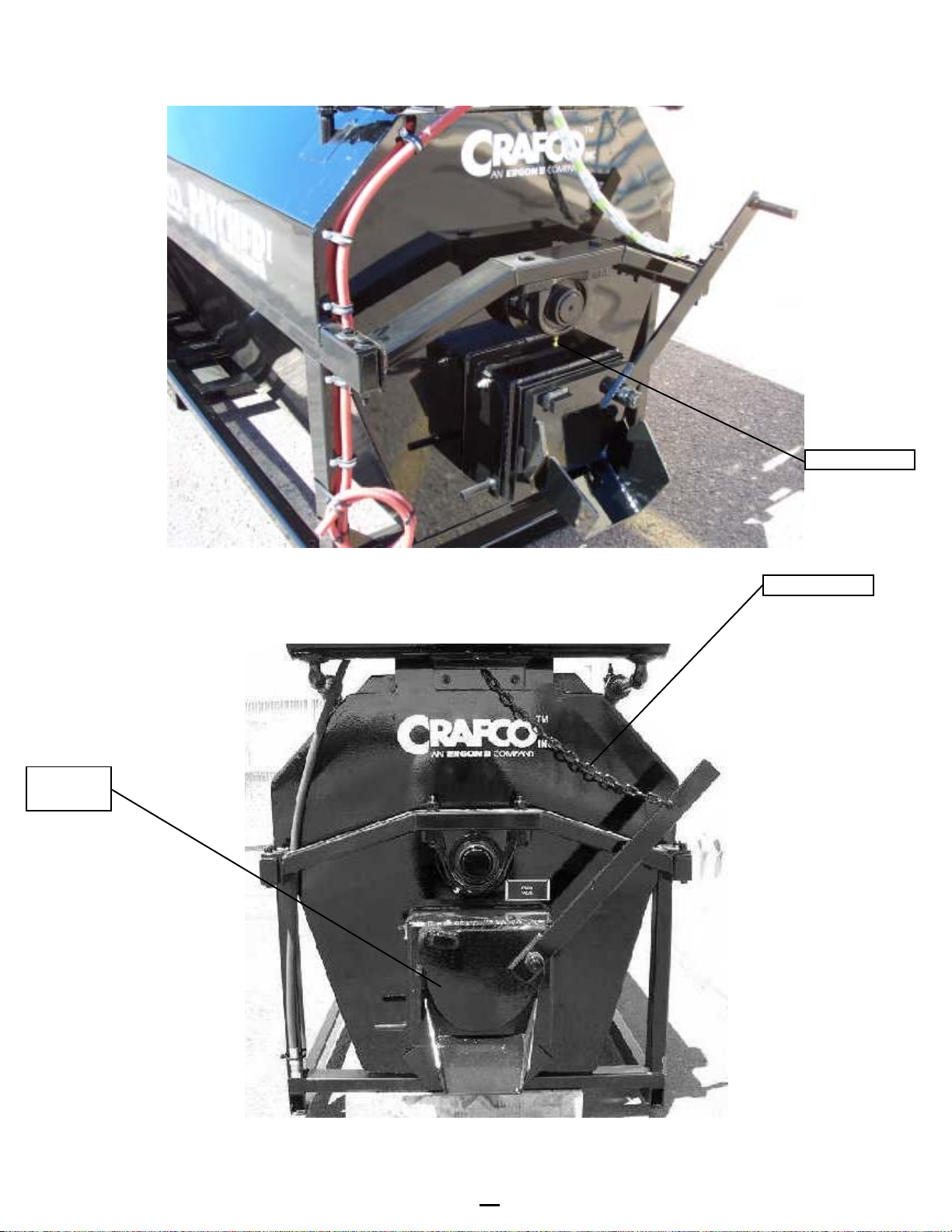
Fig. 1
Fig. 2
grease fitting
safety chain
discharge
gate

14
Fig. 3
Fig. 4
heat transfer dipstick
mixer control switch
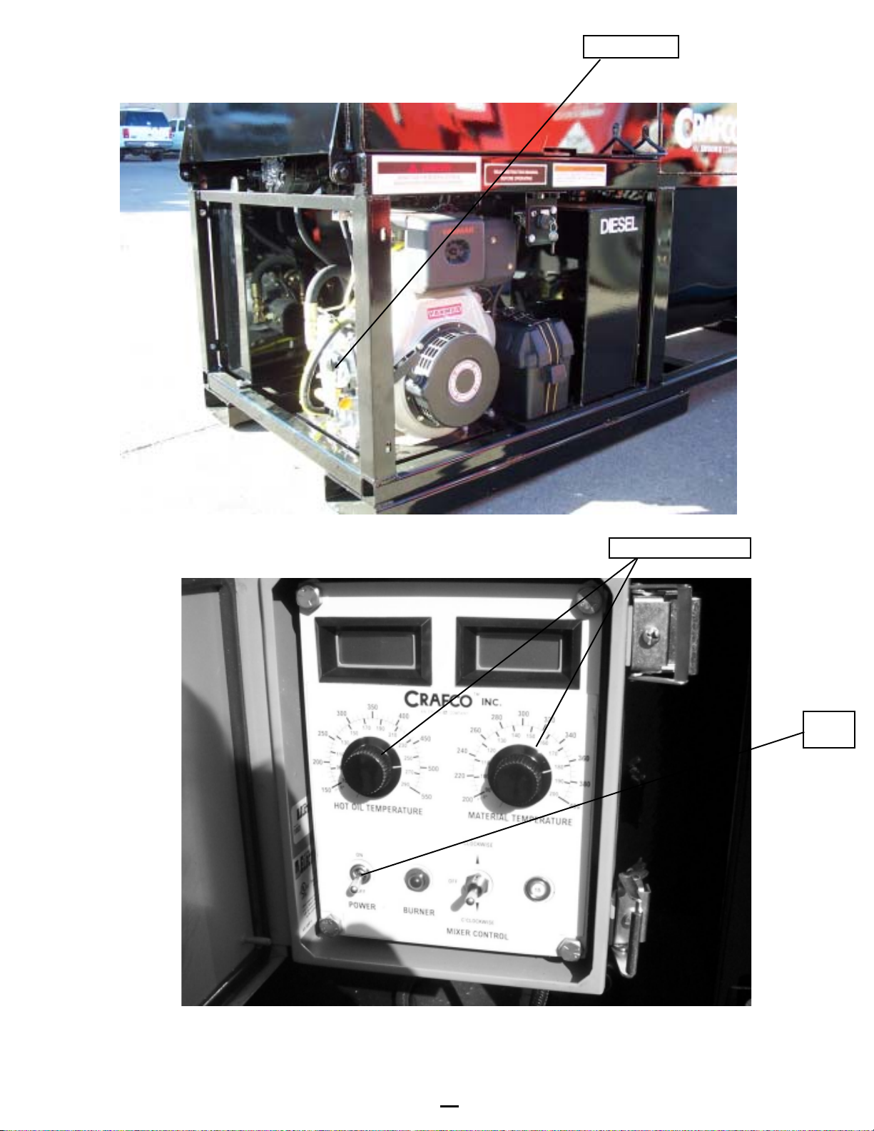
15
Fig. 5 temperature dials
Fig. 6
throttlelever
toggle
switch
16
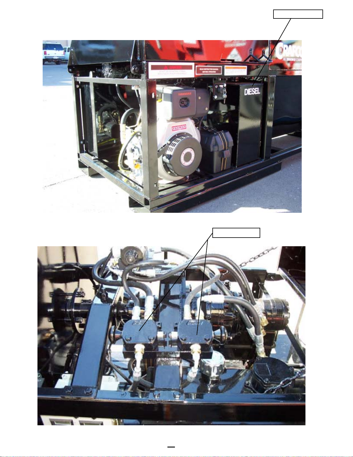
Fig. 7
Fig. 8
by-pass valves
enginefuel tank

17
SHUTDOWN PROCEDURE
1. Turnburnertoggleswitchto“OFF.”
2. Returnmixerhydraulic control switchto“OFF”position.
3. Turnoffengineby closing stop leverandturnoffkey.
STORING MACHINE
ThePatcherIDiesel shouldbestoredinanareawheremoisturecannotentermachine.
Extendeddowntimecancausemoisturebuildupinheatingoiltank.
Ifthere is any suspicion moisture thatmayhavecollectedinheat transfer oil, warm heat
transferfluidto300OF. for 2 to 3 hours to evaporate the moisture.
CAUTION
Extremecaremustbeusedwhenoperatingthis equipment. Safety is the result of being
carefulandpayingattentiontodetails. Certainexposedpartsofthismachine,whenoperat-
ing,reach500OF.; the material as high as 400OF. and the hydraulic fluid may reach 200OF.
Always wearprotectiveclothingandeyeprotection. Besure that all joints and fittings are tight
andleakproof. Immediately replace any hose which show signs of wear,fraying or splitting.
Tightenallbolts,nutsand screws every100hours.

18
TROUBLE SHOOTING CHART
SERVICE INSTRUCTIONS
1. Conductageneralinspectionof your machine at least once a week. Replace all worn
ordamaged parts, make any necessary adjustments and tighten all loose nuts or
screws.
2. Keep regular replacement items instockforemergencyrepairs,toavoid costly “down”
time. Refertogeneralmaintenanceitems.
3. Watchfor leaks - tighten packingon mixer if necessary.
4. Cleanmachineexternally periodically. Check with material manufacturerfor
recommendation.
5. Follow“RecommendedMaintenanceProcedures”perMaintenance Chart, page 20.
MELBORPESUACYDEMER
etatortonlliwrexiM
.wolooterutarepmettnalaeS lairetamtaehoteunitnoC
.emitenotadecalpskcolbynamooT gnisrev
eryrt&lairetamtaehoteunitnoC .rexim
erusserp/wolfciluardyhetauqedanI .leveldiulfciluardyhkcehC .yrassecenfiwolfkcehc/erusserpteseR
tnalesfoputaehwolS
foedisniehtnolairetamdezillatsyrcrodekocfopudliuB .knatlair
etam .loocotenihcamwollA .tnevloshtiwhsulfdnastisopedevomeR
gnitarepotonrenruB .ediuGgnitoohSelbuorTrenru
BeeS
levelliognitaehwoL tcerrocsileveldiulferusekaM
erutarepmetliognitaehwoL erutarepmetdednemmocertaeeS
d
ezillatsyrcsahrodloliognitaeH sruoh005yrevedednemmocersatiecalpeR
etatortonlliwrexiM
ffodenruthctiwselgg
otrexiM hctiwselggotnonruT
noitcennoceriwdaB riaperdnadniF
evlavlortnocdaB evlavecalpeR
eruliafegdritraccil
uardyH ecalperdnaevomeR
eruliafliocciluardyH ecalperdnaevomeR

19
MAINTENANCE INSTRUCTIONS
ENGINE:
Checkoildaily. Service engine perYanmar owners manual. See engine owners
manualfor additional operating andmaintenanceinstructions.
HYDRAULIC SYSTEM:
Checkhydraulic fluid daily. Change hydraulic filter after250 hours. Change hydraulic
fluidevery 500 hours of operation.
MIXER PACKING GLAND/SEALS:
Tightenglandwhile hot at40hourintervals. Do not overtighten.
MIXER SHAFT BEARINGS:
Lubricateweeklyusinga good grade of high temperature grease.
HEAT TRANSFER OIL:
Checkleveldaily. Oil should touch dipstick when 70OF. Donot overfill (see Fig. 4).
TEMPERATURE CONTROL CALIBRATION
Checkcontrolknobcalibrationweekly. Calibratebyaligningthelineonthecontrolknob
withthecalibrationlineonthescaleplate(seebelow).
20
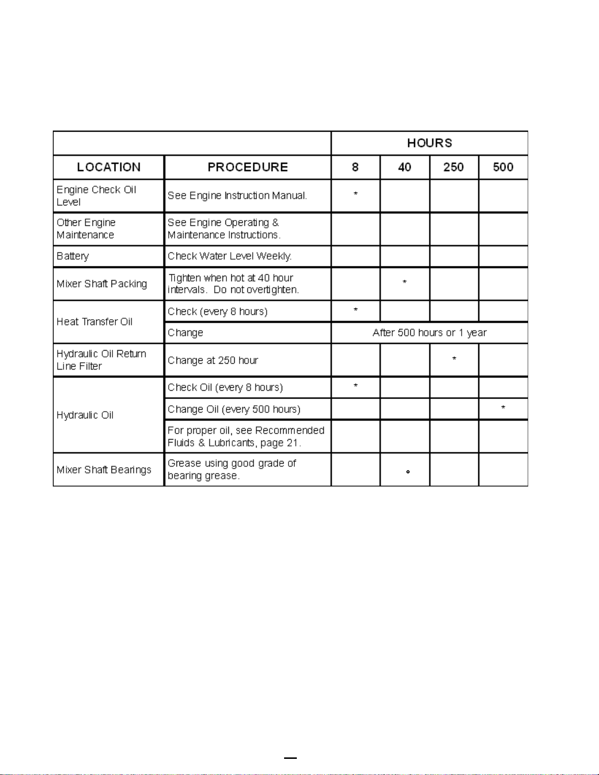
MAINTENANCE CHART
Table of contents
Popular Mixer manuals by other brands

Paramount Fitness
Paramount Fitness BM80 Installation & operation manual

Holstein Housewares
Holstein Housewares HH-09149005 manual

Linea 2000
Linea 2000 DOMO DO9180M Instruction booklet

Univex
Univex Swing Ring SRMF20 Maintenance & parts manual

Ametek
Ametek Chandler Engineering 3260 instruction manual

Russell Hobbs
Russell Hobbs THE SLICK STICK Instructions & warranty


 Specification sheet")


