Ergoswiss P D compact Series User manual

Operating instruction
Hydraulic system with Motor drive PXD compact
Document no.: B-00021
Edition 2019 09
Operating instruction EN
Copyright by Ergoswiss AG
1/25
Operating instruction - Motor drive PXD compact
to control and drive hydraulic lifting systems made by Ergoswiss AG
It is essential to read this operating instruction thoroughly before commissioning the system.
This operating instruction has to be stored in the immediate vicinity of the system.
Power cable
Control box compact-3-eco
Manual control switch Memory
Motor cable PXD
Motor PXD with front plate and housing PXD
Cable strain relief
PXD coupling for connection to the Ergoswiss
hydraulic pumps type PA, PB and PF (with Woodruff key)
Errors and technical changes reserved.
Ergoswiss AG does not assume any liability for operating
errors or using the products outside of the intended
purpose use.
At the time of delivery Ergoswiss AG will replace or re-
pair defect products within accordance with the warran-
ty provisions. In addition, Ergoswiss assumes no other
liability.
For your questions and special custom demand
Ergoswiss AG will be at your disposal.
Ergoswiss AG
Nöllenstrasse 15
CH-9443 Widnau
Tel.: +41 (0) 71 727 06 70
Fax: +41 (0) 71 727 06 79
info@ergoswiss.com
www.ergoswiss.com
1
3
5
2
7
4
6

Operating instruction
Hydraulic system with Motor drive PXD compact
Document no.: B-00021
Edition 2019 09
Operating instruction EN
Copyright by Ergoswiss AG
2/25
This operating instruction applies to:
Item description
Item number
Motor drive PAD
230 compact EU
112.00081
230 compact CH
112.00083
230 compact UK
112.00085
110 compact US
112.00087
230 compact IT
112.00089
Motor drive PBD
230 compact EU
112.00082
230 compact CH
112.00084
230 compact UK
112.00086
110 compact US
112.00088
230 compact IT
112.00090
Motor drive PFD
230 compact EU
112.00141
230 compact CH
112.00142
230 compact UK
112.00143
110 compact US
112.00145
230 compact IT
112.0014x
standard item

Operating instruction
Hydraulic system with Motor drive PXD compact
Document no.: B-00021
Edition 2019 09
Operating instruction EN
Copyright by Ergoswiss AG
3/25
Table of contents
1System description .....................................................................................................................................4
1.1 General................................................................................................................................................ 4
1.2 Intended purpose use ...........................................................................................................................4
1.3 Target group and prior knowledge .........................................................................................................4
1.4 Performance characteristics ...................................................................................................................5
1.4.1 PXD motor.......................................................................................................................................5
1.4.2 Control box PXD compact-3-eco.........................................................................................................5
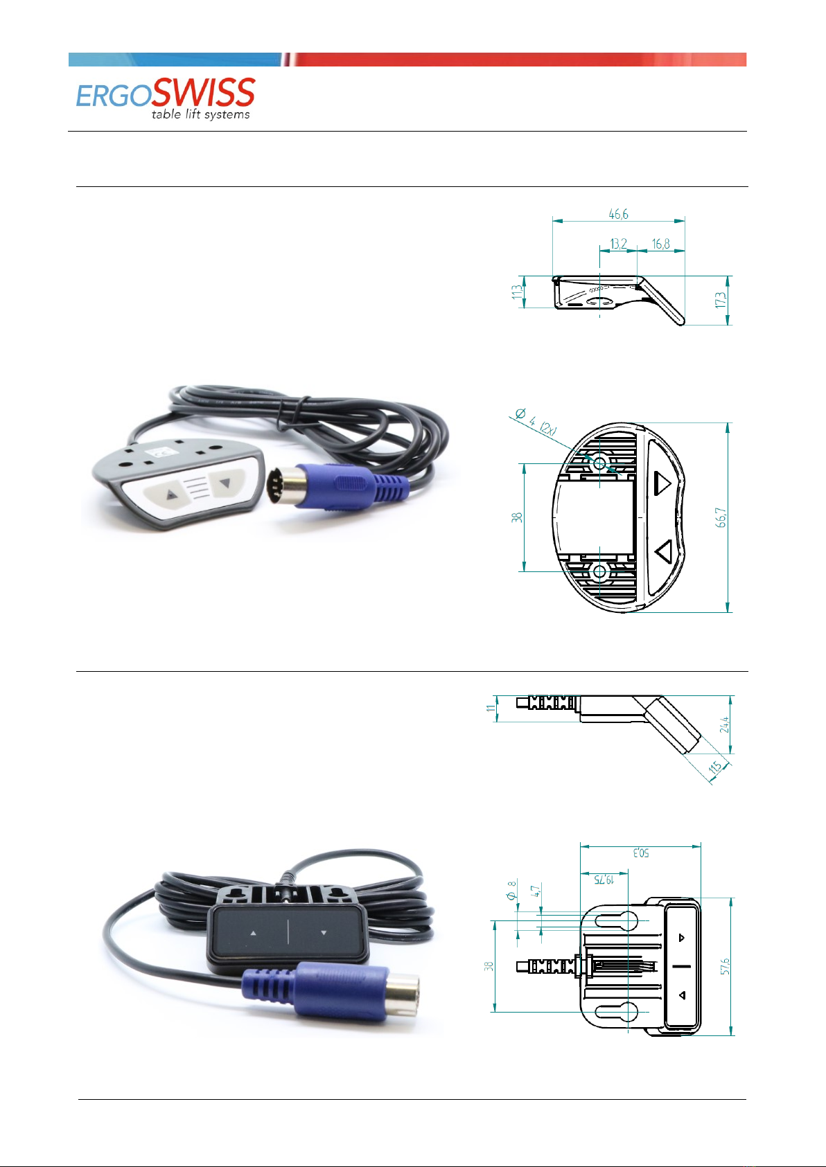
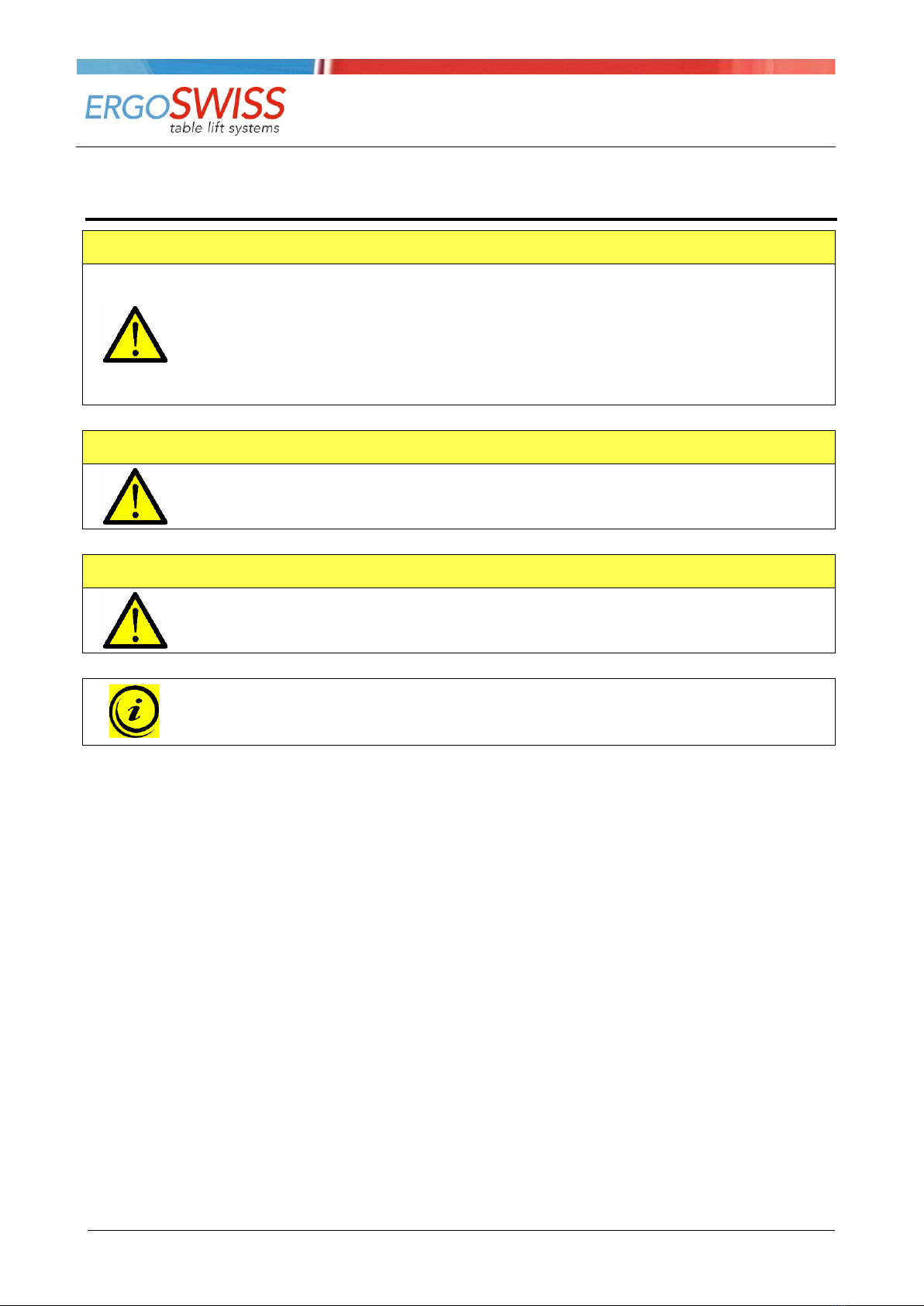
1.4.3 Manual control switch Up / Down and Memory....................................................................................5
2Safety requirements ...................................................................................................................................6
2.1 Explanations of the symbols and notes ...................................................................................................6
2.2 Basic safety instructions ........................................................................................................................7
3Preperation for first initial operation .........................................................................................................8
3.1 Mounting and wiring of the motor ..........................................................................................................8
3.2 Mounting and wiring of the control box...................................................................................................9
3.3 Mounting of the manual control switch ................................................................................................. 12
3.3.1 Manual control switch Memory ........................................................................................................ 12
3.3.2 Manual control switch Memory Touch............................................................................................... 12
3.3.3 Manual control switch Up / Down Front ............................................................................................ 13
3.3.4 Manual control switch Up / Down Touch........................................................................................... 13
4Initial operation ....................................................................................................................................... 14
4.1 Initial operation with manual control switch Memory.............................................................................. 15
4.2 Initial operation with manual control switch Up / Down .......................................................................... 15
5Operation ................................................................................................................................................. 16
5.1 Drive Up / Down................................................................................................................................. 16
5.2 Duty cycle monitoring ......................................................................................................................... 16
5.3 Saving a memory position (Only with manual control switch type Memory!)............................................. 16
5.4 Approaching a stored position (Only with manual control switch type Memory!) ....................................... 16
5.5 Setting the shown height on the display (Only with manual control switch type Memory!) ......................... 17
5.6 Reset of the control box (Only with manual control switch type Memory!)................................................ 17
5.6.1 Redefine end positions («S 7»)........................................................................................................ 17
5.6.2 Reset control box to factory settings («S 0») .................................................................................... 17
6Synchronous operation of 2, 3 or 4 control boxes .................................................................................. 18
6.1 Cable connections............................................................................................................................... 18
6.2 Commissioning the synchronized systems ............................................................................................. 19
6.3 Operation scenarios - FAQ ................................................................................................................... 19
7Safety strip - Squeezing protection......................................................................................................... 20
7.1 Technical Data ................................................................................................................................... 20
7.2 Connecting the safety strip .................................................................................................................. 21
8Maintenance and disposal ....................................................................................................................... 22
8.1 Maintenance and cleaning ................................................................................................................... 22
8.2 Repairs and spare parts ...................................................................................................................... 22
8.3 Disassembly and disposal .................................................................................................................... 22
8.4 Electrical and Electronic Equipment Act................................................................................................. 22
8.5 Error messages on the display (Only with manual control switch type Memory!)....................................... 23
8.6 Click codes......................................................................................................................................... 24
8.7 Trouble-shooting ................................................................................................................................ 24
9Declaration of Incorporation ................................................................................................................... 25

Operating instruction
Hydraulic system with Motor drive PXD compact
Document no.: B-00021
Edition 2019 09
Operating instruction EN
Copyright by Ergoswiss AG
4/25
1System description
1.1 General
The basic functionality of a hydraulic lifting system by Ergoswiss AG (motor drive →pump →tubing →
cylinder) is the lifting, lowering and tilting of work surfaces, machine parts, profile systems etc.
All Ergoswiss hydraulic lifting systems with the pump types PA, PB and PF (with woodruff key) can be driven
by the motor drive PXD compact. The motor drive PXD compact consists of a motor PXD, a control box com-
pact-3-eco, a manual control switch Memory, different connection cables and a plastic housing.
The intelligent control box compact-3-eco is equipped with a highly efficient switched-mode power supply
(SMPS) and a monitoring software (overload, duty cycle, overheat). Due to the optimised driving comfort,
the end positions are gently approached as low-speed zones up to the standstill. Additional functions, such
as the synchronisation of two to four drives or the connection of safety strips (squeezing protection) can be
used.
With the manual control switch Memory the hydraulic system can be operated comfortably, the work surface
will be adjusted steplessly in its height. The current height of the work surface is continuously shown on the
display (cm or inches). Up to four different memory positions can be stored and approached individually.
1.2 Intended purpose use
The motor drive PXD compact is exclusively intended to control and drive Ergoswiss AG hydraulic lifting sys-
tems. While mounting the lifting system into a greater system and while operating the system, the specified
normal operation of the entire system is to be complied with. Commissioning is prohibited until the entire
system complies with the provisions of EG Machinery Directives 2006/42/EG (Machinery Directive).
The system is only to be installed and used indoors in dry conditions.
The operating temperature range is at 0° C to +40° C.
The motor drive PXD compact must not be overloaded. Do not exceed the given maximum lifting loads of
the hydraulic lifting systems.
The lifting system can be continuously operated for a maximum of 2 minutes. Afterwards a pause of at least
18 minutes needs to be observed before the system can be operated again. To avoid overheating of the sys-
tem a duty cycle of 2/18 (ON/OFF) should be maintained in general.
1.3 Target group and prior knowledge
This operating instruction addresses the following groups of people:
The commissioning staff, who install and commission the motor drive PXD compact and the Ergoswiss AG
hydraulic system as an incomplete assembly into a work station, a machine, ect. For commissioning activi-
ties, mechanical and electrical knowledge is prerequisite. Before using the system for the first time the oper-
ating instruction must be read.
The end user controls the complete system via manual control switch and adjusts its height.
Before using the system for the first time the operating instruction must be read and understood.

Operating instruction
Hydraulic system with Motor drive PXD compact
Document no.: B-00021
Edition 2019 09
Operating instruction EN
Copyright by Ergoswiss AG
5/25
1.4 Performance characteristics
1.4.1 PXD motor
Constructional data
Brush type commutation, worm gear
Nominal voltage
24 V
Nominal torque
2 Nm
Idle speed
160 min-1
Nominal power
92 W
Nominal current
4 A (no-load current 3 A)
Protection class (DIN EN 60529)
IP 30
Gear ratio
2 : 53
Dimensions (L, W, H)
166 x 70 x 60 mm
Weight
1’210 g
1.4.2 Control box PXD compact-3-eco
Supply voltage
EU: 207 - 254.4 V / 50 Hz US: 90 –127 V / 50-60 Hz
Primary standby power
<0.6 W
Performance rate
83 % @ 300 W input power
Hall sensor supply voltage
5 VDC +/- 10%; 250 mA
Ambient temperature
0 –40 ℃
Humidity (operating)
5 –85 % (non-condensing)
Humidity (when stored)
5 –90 % (non-condensing)
Protection class (DIN EN 60529)
IP 20
Performance Level (DIN EN 13849-1)
PL b
Power supply cable (length)
3’000 mm
Dimensions (L, W, H)
264 x 103 x 37 mm
Weight
418 g
1.4.3 Manual control switch Up / Down and Memory
Supply voltage
5 VDC ± 10 %
Power consumption (average)
75 mA
Service life (cycles of operation)
10‘000
Ambient temperature
0 –40 ℃
Cable length
1’800 mm
Protection class (DIN EN 60529)
IP 30

Operating instruction
Hydraulic system with Motor drive PXD compact
Document no.: B-00021
Edition 2019 09
Operating instruction EN
Copyright by Ergoswiss AG
6/25
2Safety requirements
2.1 Explanations of the symbols and notes
Please pay attention to the following explanations of the symbols and notes. They are classified according to
ISO 3864-2.
DANGER
Indicates an immediate threatening danger.
Non-compliance with this information can result in death or serious personal injuries (invalid-
ity).
WARNING
Indicates a possible dangerous situation.
Non-compliance with this information can result in death or serious personal injuries (invalid-
ity).
ATTENTION
Indicates a possible dangerous situation.
Non-compliance with this information can result in damage to property or light to medium
personal injuries.
NOTE
Indicates general notes, useful operator advice and operating recommendations which do
not affect safety and health of the user.

Operating instruction
Hydraulic system with Motor drive PXD compact
Document no.: B-00021
Edition 2019 09
Operating instruction EN
Copyright by Ergoswiss AG
7/25
2.2 Basic safety instructions
The safety instructions must be paid attention to. If the system is operated improperly, it can cause danger
to people and objects!
It is essential to read this operating instruction thoroughly before commissioning the system. This operating
instruction has to be stored in the immediate vicinity of the system.
→In no case the control box may be opened! There is the risk of an electrical shock.
→Modifications or changes to the control box, the manual control switch, the motor and any connection
cables are forbidden!
→The control box must only be operated with mains voltage indicated on the name plate!
→The supplied power cable must be used. It is forbidden to operate the control box with a damaged
power cable!
→Electrical cables must not be exposed to crushing hazard or to bending and tensile loads.
→Before connecting/disconnecting the manual control switch the power cable has to be disconnected
from the mains!
→The control box must not be operated in a potentially explosive atmosphere!
→The control box must be protected from moisture, dripping water as well as spray water!
→The control box is not suitable for continuous use. The operation/hold ratio must not exceed 2/18.
→If there is a failure (for example, if the control drives on its own, or if a push button is stuck) the power
cable is to be separated from the mains immediately! The power cable must be freely accessible at any
time.
→While using the height adjustment of the work surface there is a danger of squeezing. It is important to
make sure that no objects or people are within the danger zone and no one is reaching into the danger
zone.
→This device is not intended to be used by people (including children under 8) with restricted physical,
sensory or mental abilities or with a lack of experience and/or knowledge, unless they are supervised by
a person responsible for safety or they have received instructions by this very person on how to operate
the device.
→Children under 8 should be supervised to ensure that they do not play with the device.
→If the power cable of the drive is damaged it must be replaced by the manufacturer, the manufacturer's
customer service or by a similar qualified person.
→Only use a dry or a damp cloth to clean the control box! Before cleaning, the power cable has to be
separated from the mains!

Operating instruction
Hydraulic system with Motor drive PXD compact
Document no.: B-00021
Edition 2019 09
Operating instruction EN
Copyright by Ergoswiss AG
8/25
3Preperation for first initial operation
Before commissioning the lifting system, the entire system must be assembled correctly according to the as-
sembly instruction. Commissioning is prohibited until the entire system complies with the provisions of EG
Machinery Directives 2006/42/EG. For this, a risk analysis of the complete system must be carried out so
that you can react to possible residual dangers (for example by constructive measures or by instructions in
the operating instructions and/or by safety instructions on the system).
3.1 Mounting and wiring of the motor
1. Connect plugs A and B of the motor cable PXD to the motor.
NOTE
Plug Amust be connected to the motor in a way its cable shows in the direction of the gear
shaft (in the direction of the arrow).
2. Place both lines of the motor cable into the cable strain relief. The bendable tab of the cable strain
relief should point towards the motor. The distance between cable strain relief and the connectors
A+B should be approx. 140mm.
3. Firmly compress the cable strain relief while inserting it into the slot of the motor front panel.
A
B
A
B
M1
M2
Motor cable PXD

Operating instruction
Hydraulic system with Motor drive PXD compact
Document no.: B-00021
Edition 2019 09
Operating instruction EN
Copyright by Ergoswiss AG
9/25
The plastic housing PXD can be
snapped on the motor after wir-
ing the motor and mounting the
cable strain relief. Snap-fits in-
tegrated in the housing clasp
the cylinder of the motor.
3.2 Mounting and wiring of the control box
Mounting of the control box underneath a table top:
ATTENTION
During mounting of the control box the power cable must be disconnected from the mains!
1. Place the control box to the desired location and mark the drill holes with a pen.
2. Pre-drill two holes (Ø 3 mm).
Be careful not to drill through the table top!
3. The control box is mounted with two screws (cap screws DIN7981C 4.8xL, cap-Ø 9.5 mm).
NOTE
The screws may be tightened with a maximum torque of 2 Nm!

Operating instruction
Hydraulic system with Motor drive PXD compact
Document no.: B-00021
Edition 2019 09
Operating instruction EN
Copyright by Ergoswiss AG
10/25
Motor socket 1 (M1)
Motor socket 2 (M2)
(S) Socket for manual control switch
(D) Connection for safety strip or sync cable
(P) Power socket
(F) Connection for functional grounding (e.g. ESD)
ATTENTION
Connecting homemade products to the control box is prohibited!
Only use supplied components.
1. Connect the motor cable to the control box. The continuous cable must be plugged into the motor
socket M1, the split cable must be plugged into the motor socket M2.
2. Connect the manual control switch to the control box.
3. Connect the power cable to the control box.
4. Connect the power cable to the mains. (Clicking sound →ready for initial operation)
NOTE
The drive does not work, if the motor cable plugs (M1 + M2) are connected to the wrong
socket.
1
2
S
D
P
F
Connect optional
components
M2
M1

Operating instruction
Hydraulic system with Motor drive PXD compact
Document no.: B-00021
Edition 2019 09
Operating instruction EN
Copyright by Ergoswiss AG
11/25
NOTE
Before connecting the power cable to the mains the following must be verified:
→Does the mains voltage correspond to the value on the name plate of the control box?
→Are the plugs of the motor cable connected to the correct sockets (M1, M2)?
→Is the entire lifting system assembled according to the assembly instructions?
NOTE
The motor cable, connecting the control box to the motor, has a length of 950 mm. If need-
ed, up to 5 motor extension cables can be connected. They have a length of 1’200 mm.
→124.00137: PXD compact Extension cable 1’200 mm Motor
NOTE
The cable of the manual control switch has a length of 1’800 mm. If needed it can be ex-
panded with up to 3 extension cables. They have a length of 1’000 mm.
→124.00071: PXD Extension cable 1’000 mm Manual control switch

Operating instruction
Hydraulic system with Motor drive PXD compact
Document no.: B-00021
Edition 2019 09
Operating instruction EN
Copyright by Ergoswiss AG
12/25
3.3 Mounting of the manual control switch
3.3.1 Manual control switch Memory
1. Position the mounting plate underneath the table plate.
The control panel must overhang below the work
surface!
2. Fasten the mounting plate using the mounting screws.
Be careful not to drill through the table top!
3. Slide the manual control switch onto the mounting pla-
te.
3.3.2 Manual control switch Memory Touch
1. Position the manual control switch at the desired loca-
tion underneath the table top.
The control panel must overhang below the work
surface!
2. Fasten the manual control switch using the mounting
screws.
Be careful not to drill through the table top!
Operating instruction
Hydraulic system with Motor drive PXD compact
Document no.: B-00021
Edition 2019 09
Operating instruction EN
Copyright by Ergoswiss AG
13/25
3.3.3 Manual control switch Up / Down Front
1. Position the manual control switch at the desired loca-
tion underneath the table top.
The control panel must overhang below the work
surface!
2. Fasten the manual control switch using the mounting
screws.
Be careful not to drill through the table top!
3.3.4 Manual control switch Up / Down Touch
1. Position the manual control switch at the desired loca-
tion underneath the table top.
The control panel must overhang below the work
surface!
2. Fasten the manual control switch using the mounting
screws.
Be careful not to drill through the table top!
Operating instruction
Hydraulic system with Motor drive PXD compact
Document no.: B-00021
Edition 2019 09
Operating instruction EN
Copyright by Ergoswiss AG
14/25
4Initial operation
ATTENTION
Before commissioning the lifting system, the entire system must be assembled correctly ac-
cording to the as-sembly instruction. Commissioning is prohibited until the entire system
complies with the provisions of EG Machinery Directives 2006/42/EG. For this, a risk analysis
of the complete system must be carried out so that you can react to possible residual dan-
gers (for example by constructive measures or by instructions in the operating instructions
and/or by safety instructions on the system).
ATTENTION
While using the height adjustment of the work surface there is a danger of squeezing. It is
important to make sure that no objects or people are within the danger zone and no one is
reaching into the danger zone.
ATTENTION
The lowest block position must always be reachable. The lifting element is not allowed to hit
a stop before it reached its lowest block position. Otherwise air will be pulled into the system
or too much pressure will build up.
NOTE
While commissioning the control box works with only half power and half speed. The system
should be fully loaded after finishing the initial operation.

Operating instruction
Hydraulic system with Motor drive PXD compact
Document no.: B-00021
Edition 2019 09
Operating instruction EN
Copyright by Ergoswiss AG
15/25
4.1 Initial operation with manual control switch Memory
The display is flashing «068» (US –110 V version «027»)
1. Press the button to drive to the desired lower end position (or to the under block position).
The system moves downwards at half speed. Upward movement is disabled.
2. Press the buttons
1
(plus) and
2
(minus) to set the current height of the work surface on the
display. (in cm, US - 110 V version in inch)
3. To confirm, press
S
(Save).
After confirmation the display changes to «088» (US - 110 V version «035») (still flashing).
4. Press the button to drive to the desired upper end position (or to the upper block position).
5. Press the buttons
1
(plus) and
2
(minus) to set the current height of the work surface on the
display. (in cm, US - 110 V version in inch)
6. To confirm, press
S
(Save).
After confirmation the height is displayed (no more flashing) and the initial operation is completed.
NOTE
The control box automatically offsets the end positions by one motor turn.
Depending on the combination of systems (hydraulic transmission ratio), the system stops
its movement 3 mm, 5 mm or 10.5 mm before the defined end position.
4.2 Initial operation with manual control switch Up / Down
1. Press the button to drive to the desired lower end position (or down to the block position).
The system moves downwards at half speed. Upward movement is disabled.
2. Press the buttons and at the same time for at least 5 seconds.
3. Press the button to drive to the desired upper end position (or up to the block position).
4. Press the buttons and at the same time for 5 seconds.
NOTE
The control box automatically offsets the end positions by one motor turn.
Depending on the combination of systems (hydraulic transmission ratio), the system stops
its movement 3 mm, 5 mm or 10.5 mm before the defined end position.

Operating instruction
Hydraulic system with Motor drive PXD compact
Document no.: B-00021
Edition 2019 09
Operating instruction EN
Copyright by Ergoswiss AG
16/25
5Operation
5.1 Drive Up / Down
This function is used for easy height adjustment of the system.
→Press the button or .
Keep the button pressed until the desired working height is reached.
5.2 Duty cycle monitoring
The duty cycle monitoring checks for the operation/hold ratio. To avoid overheating of the system a duty cy-
cle of 2/18 (ON/OFF) should be maintained.
The maximum continuous operating time is 2 minutes. Afterwards a pause of at least 18 minutes needs to
be observed before the system can be operated again.
5.3 Saving a memory position (Only with manual control switch type Memory!)
With this function it is possible to memorise a certain position/height and approach it at a later time by
pushing one button. With the four memory buttons up to four different positions can be stored and ap-
proached.
1. Drive to the desired position and press the button
S
(Save).
Display:
2. Press one of the buttons
1
2
3
4
.
After pressing a memory button the display shows «S» and the number of the pressed button.
Example:
After saving there is a double click sound, and after approx. 2 seconds the current height is dis-
played again.
Example:
5.4 Approaching a stored position (Only with manual control switch type Memory!)
This function is designed to approach a stored position.
→Press one of the buttons
1
2
3
4
.
The system approaches and stops at the stored position.

Operating instruction
Hydraulic system with Motor drive PXD compact
Document no.: B-00021
Edition 2019 09
Operating instruction EN
Copyright by Ergoswiss AG
17/25
5.5 Setting the shown height on the display (Only with manual control switch type Memory!)
The displayed height can be adjusted with this feature.
1. Drive to any desired height and press the button
S
(Save).
Display:
2. Keep the button pressed for about 5 seconds, until the display starts flashing.
Example:
3. Now the button (plus) or (minus) can be used to set the current height.
While doing so, the system does not move!
4. With the correctly set value the new height is saved by pressing
S
(Save).
5.6 Reset of the control box (Only with manual control switch type Memory!)
5.6.1 Redefine end positions («S 7»)
1. Press the buttons
1
,
2
and simultaneously, until «S 5» or «S 7» is displayed.
2. Press the button until «S 7» appears on the display.
3. Press the button
S
(Save).
The display is flashing «068»
→carry out initial operation according to chapter 4.
5.6.2 Reset control box to factory settings («S 0»)
1. Press the buttons
1
,
2
and simultaneously, until «S 5» or «S 7» is displayed.
2. Press the button until «S 0» appears on the display.
3. Press the button
S
(Save).
The display is flashing «068»
→carry out initial operation according to chapter 4.

Operating instruction
Hydraulic system with Motor drive PXD compact
Document no.: B-00021
Edition 2019 09
Operating instruction EN
Copyright by Ergoswiss AG
18/25
6Synchronous operation of 2, 3 or 4 control boxes
6.1 Cable connections
By cascading multiple control boxes, multiple motor drives can be controlled simultaneously with just one
manual control switch. The control boxes can be connected using the PXD SYNC-2 cable (124.00088) or the
PXD SYNC-4 cable (124.00089).
PXD SYNC-2 cable
With the SYNC-2 cable two control boxes PXD compact can be
connected and synchronised.
→The length of the SYNC-2 cable is 550 mm.
The SYNC cable cannot be extended. If necessary, the motor
cables can be extended!
NOTE
Always do reset before disconnecting!
Disconnect plug carefully -> risk of damage
PXD SYNC-4 cable
With the SYNC-4 cable 2, 3 or 4 control boxes PXD compact
can be connected and synchronised.
→The length of SYNC-4 cable is 1’800 mm
→Two connected SYNC-4 cables have a length of 2’000
mm
Each control box needs one SYNC-4 cable.
The SYNC cable cannot be extended. If necessary, the motor
cables can be extended!
The SYNC-4 cables of each control box are to be connected.
→The loose ends do not have to be connected. Howev-
er, connecting the loose ends will not have any influ-
ence to the system.

Operating instruction
Hydraulic system with Motor drive PXD compact
Document no.: B-00021
Edition 2019 09
Operating instruction EN
Copyright by Ergoswiss AG
19/25
6.2 Commissioning the synchronized systems
1. Wire the drives according to instructions.
2. Connect the control boxes using the PXD SYNC-2 cable for two control boxes, or the PXD SYNC-4
cable for 2, 3 or 4 control boxes.
3. Only one manual control switch is necessary. The control box with the manual control switch is the
master control box. All other control boxes are subordinated.
4. Connect the control boxes to the mains.
(Clicking sound of the control box →ready for initial operation)
5. Carry out the initial operation according to chapter 4.
ATTENTION
The SYNC cable must be connected to the control box before the control box is connected to
the mains. If the SYNC cables are connected afterwards, they will not be recognised by the
control box and only one drive will move, which can lead to jamming of the entire system.
NOTE
When disconnecting the SYNC cable uncarefully, the plug can be ripped out of the print
platine!
6.3 Operation scenarios - FAQ
Scenario: connecting the manual control switch to another control box
→
Display blinks «- - -«
→Manual control switch doesn’t work
→Manual control switch ONLY works on the the master control box
Scenario: disconnecting or reconnecting the synchronisation cable
→
Display blinks «000»
→
Then display blinks «E93»
→Perform a Reset «S 0» according to chapter 5.6.2 (all controls are reset to factory settings)
Scenario: power cut
→Control box saves all stored positions
→Synchronisation is stored
→Getting back the power, the system can be used as usual. No initial operation necessary.
Scenario: power cut on only one control box
→
Display blinks «000»
→
Then display blinks «E93»
→Perform a Reset «S 0» according to chapter 5.6.2 (all controls are reset to factory settings)

Operating instruction
Hydraulic system with Motor drive PXD compact
Document no.: B-00021
Edition 2019 09
Operating instruction EN
Copyright by Ergoswiss AG
20/25
7Safety strip - Squeezing protection
With lifting systems of Ergoswiss AG it is important to make sure that no objects or people are trapped dur-
ing the lifting movement. ->Danger of squeezing
Attach the safety strip to an assumed squeeze zone. If the safety strip gets squeezed while the system
moves, the motor will stop instantly and turn back for one motor turn.
Depending on the combination of systems (hydraulic transmission ratio), the system stops its movement
3mm, 5mm or 10.5mm before the defined end position.
The safety strip compact (124.00105) consists of:
7.1 Technical Data
Functional properties of the contact tube
Contact angle < 80 °
Switching pressure < 25 N at 23 °C
Switching travel < 2mm at 23 °C
Bending radii minimal B1120 mm / B2150 mm /
B320 mm / B420 mm
Max. tensile load 20 N
Electrical properties
Terminal resistance 2.2 kOhm
Max. switching capacity 250 mW
Max. Voltage DC 24 V
Current min/max 1 mA / 10 mA
Adapter cable sadety strip comp.
124.00106
End piece with cable / RJ45
124.00107
Contact tube
124.00101
End piece with
resistor 2.2kΩ
124.00118
185 mm
2’500 mm
variable
10 mm
This manual suits for next models
32
Table of contents


