manuals.online logo
Brands
  1. Home
  2. •
  3. Brands
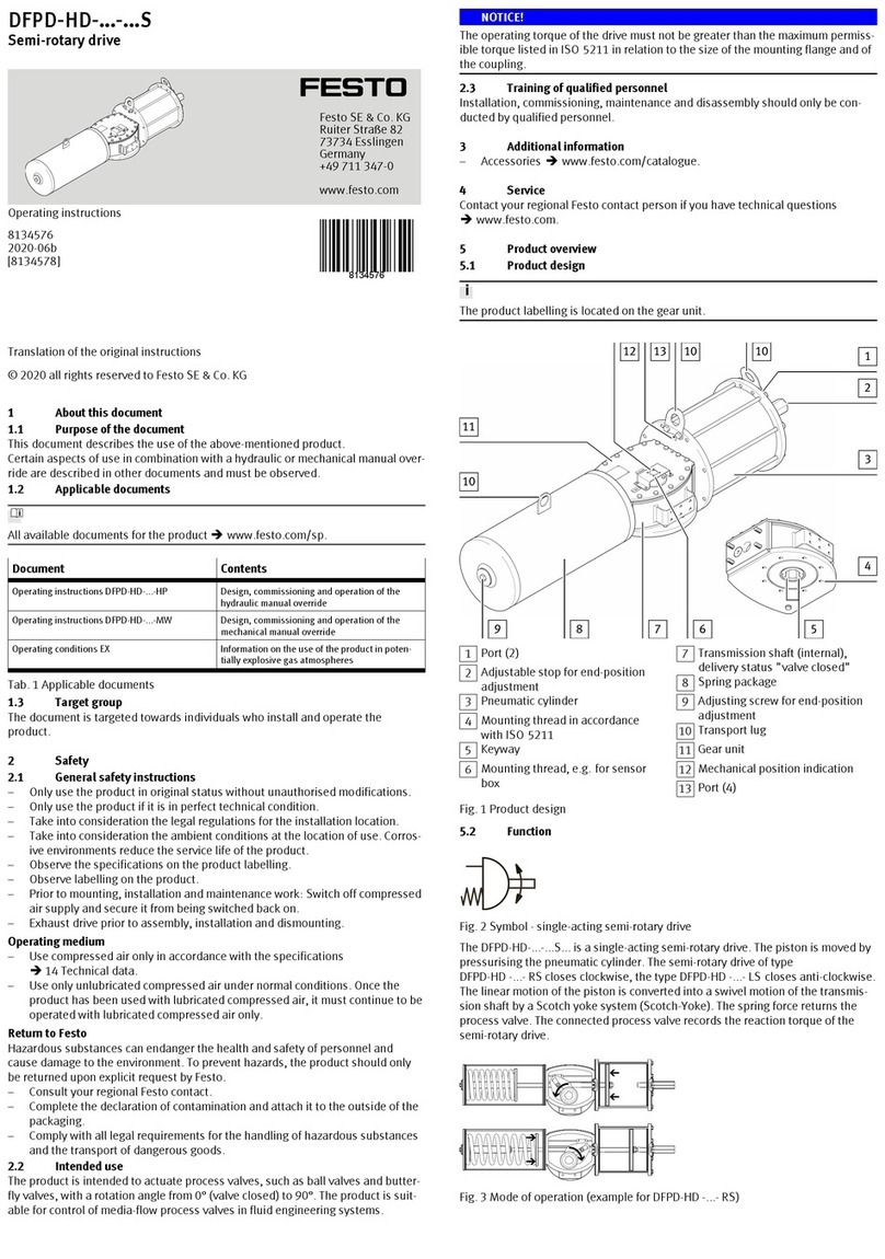
  4. •
  5. Festo
  6. •
  7. DC Drive
  8. •
  9. Festo EMCA-EC-67 CO Series User manual

Festo EMCA-EC-67 CO Series User manual

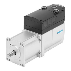
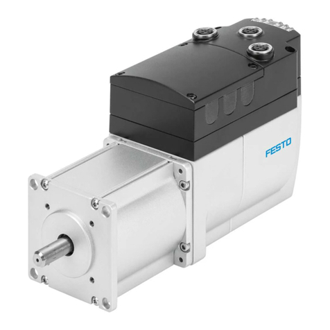
EMCA-EC-67-...-CO
Festo AG & Co. KG
Ruiter Straße 82
73734 Esslingen
Germany
+49 711 347-0
www.festo.com
Brief description
Translation of the original instructions
8080445
1710a
[8080447]
Integrated drive EMCA-EC-67-...-CO English...............................
CANopen®and CiA®are registered trademarks of the respective trademark
owners in certain countries.
For all available product documentation èwww.festo.com/pk.
This brief description is intended solely for initial information. The user documen
tation for the product also includes the following documents:
User documentation for the product
Manual
EMCA-EC-SY-...
Device and functional description;
Mounting, installation, commissioning and diagnostics
Manual
EMCA-EC-S1-...
Description of the safety function “Safely switched-off torque” (Safe
torque off/STO)
Manual
EMCA-EC-C-HP-...
Description of the device profile FHPP (Festo Handling and
Positioning Profile)
Manual
EMCA-EC-C-CO-...
Description of the device profile CiA 402
Help for the EMCA FCT
plug-in
Online help of the Festo Configuration Tool (FCT) for commissioning
and parameterisation
Special documentation
EMCA-EC_UL-...
Requirements for operating the product in the USA and Canada in
accordance with certification by Underwriters Laboratories Inc. (UL)
1 Safety
 Always observe the safety instructions and warnings in the documentation of
the product and of the other components used.
 Before mounting and installation work, switch off supply voltage and secure it
against being switched on again. Only switch on the supply voltage again when
mounting and installation work is complete.
 Never remove or insert a plug connector when the motor controller is powered.
 Observe the handling specifications for electrostatically sensitive devices.
 Only enable the controller if the drive has been professionally installed and fully
parameterised.
 Do not carry out repairs on the device. If defective, replace the device.
 Besides the 4 screws on the housing cover, do not loosen any additional screws.
Warning
Danger of burns from hot housing surfaces.
Contact with the motor housing can cause burn injuries. This can frighten people
and cause them to act in an unpredictable manner. This can lead to other forms
of secondary damage.
 Make sure that unintentional contact is not possible.
 Inform operating and maintenance staff about the possible hazards.
 Let the drive cool down to room temperature before maintenance work.
Warning
Rapidly rotating motor shaft with high torque.
Clothing, jewellery and hair can be caught and wrapped around the shaft. People
can be injured as a result.
 Make sure that clothing, jewellery or hair cannot be caught by the rotating
motor shaft.
 Ensure that clothing fits tightly.
 Personnel with long hair must wear hair nets.
Caution
Rapidly rotating motor shaft with high torque.
Contact with the motor shaft can cause burn injuries and abrasions.
 Ensure that the rotating motor shaft and components attached to it cannot be
touched.
Note
Gas formation with fire risk.
If cleaning agents make contact with the hot surface of the motor, gases can
form and ignite.
 Prior to cleaning work, let the drive cool down to room temperature.
 Pay attention to the instructions for use of the cleaning agent.
1.1 Use for intended purpose
The product is intended for driving and controlling electromechanical drives. The
product is intended for installation in a machine.
Use exclusively:
– In perfect technical condition
– In original status without unauthorised modifications; only the expansions de
scribed in the documentation supplied with the product are permitted.
– Within the limits of the product defined through the technical data
– In an industrial environment.
The product is intended for use in industrial environments. Outside of industrial
environments, e.g. in commercial and mixed-residential areas, actions to suppress
interference may have to be taken.
1.2 Intended use of the STO function
The STO function (Safe torque off ) in accordance with EN61800-5-2 is intended to
shut down the torque of the integrated motor. The STO function prevents unexpec
ted start-up of the integrated motor. The STO function may only be used in applica
tions in which the specified safety characteristics suffice.
Safety characteristics
The product’s STO function fulfils requirements for the following characteristic
safety values:
– PLd/cat.3 in accordance with ISO13849-1 (Performance Level/PL)
– SIL 2 in accordance with EN61800-5-2 (Safety Integrity Level/SIL)
– SILCL 2 in accordance with IEC 62061 (Claim Limit/CL)
The achievable safety level depends on the other components used to implement
the safety function.
To protect against unintended motor start-up, the controller of the product must
be activated via the connection [X6] with the category required for the application
in accordance with ISO 13849-1, e.g. via an external safety relay.
Qualification of skilled personnel (requirements for staff)
The product may be placed in operation only by a qualified electro technician, who
is familiar with the topics:
– installation and operation of electrical control systems
– applicable regulations for operating safety-engineering systems
– applicable regulations for accident prevention and operational reliability
– documentation for the product
Diagnostic coverage (DC) for the safety function
Diagnostic coverage is determined by inclusion of the product in the control chain
and the measures implemented for the diagnostics. In order to achieve the speci
fied diagnostic coverage, the status of the acknowledgment contact must be
evaluated by the control system each time the STO function is requested. If a
potentially dangerous malfunction is recognised during the diagnostics, appropria
te measures must be taken to maintain the safety level.
Note
The device cannot detect a cross circuit in the input circuit by itself.
 If required, use a safety switching device with cross-circuit detection.
1.3 Possible misuse of the STO function
The following foreseeable misuses are among those not approved as intended use:
– Bridging of the STO function
– Applications where switching off can result in hazardous movements or condi
tions
Note
The STO function must not be used as the sole safety function for drives that are
subject to permanent torque or force (e.g. suspended loads, vertical axes).
1.4 Obligations of the operator for the safety function
The implemented safety function must be subjected to a regular and documented
performance test by a specialist during the period of use of the machine.
The frequency of these tests must be determined by the machine operator based
on the specifications of the machine manufacturer.
 Check the EMCA at least once per year.
2 Requirements for product use
 Provide the complete product documentation to the following personnel:
– the design engineer and the installer of the machine or system
– the personnel responsible for commissioning
 Store the documentation throughout the entire product lifecycle.
 Ensure compliance with the specifications in this documentation. Also observe
the information in the documentation for the other components and modules
(e.g. axial kit, gear unit, actuator, lines, etc.).
 Take into consideration all of the legal regulations that are applicable for the
installation site, as well as the following documents:
– regulations and standards
– regulations of the testing organisations and insurers
– national specifications
For correct and safe use of the STO function:
 Conduct a risk assessment for your machine.
 Comply with the specified safety characteristics (èChapter 9, Technical data).
Range of application and certifications
The EMCA with integrated STO safety function is a safety-related part of control
systems. The product has the CE marking. Certain configurations of the product
have been certified by Underwriters Laboratories Inc. (UL).
Certificates and declaration of conformity for the product
èwww.festo.com/sp .
Specified standards
Issue statuses
IEC62061:2015 ISO13849-1:2015 EN 61800-5-2:2007
2.1 Transport and storage conditions
 Protect the product during transport and storage from excessive stress factors.
Excessive stress factors include:
– mechanical stresses
– out-of-range
– moisture
– aggressive atmospheres
 Store and transport the product in its original packaging. The original packaging
offers sufficient protection from typical stresses.
2.2 Technical requirements
For correct and safe use of the product:
 Comply with the specified connection and operating conditions for all of the
connected components èChapter 9. Only compliance with the limit values or
load limits will enable operation of the product in compliance with the relevant
safety regulations.
3 Product description
3.1 Product overview
1[X1]: Parameterisation
interface (Ethernet in
terface)
2LED light guide (6x) –
3 used
3[X3]: CAN OUT
4Cable throughfeeds
(6 x)
5Motor flange
6Through-hole for
mounting (4 x)
7Mounting thread (4 x)
thread M4
8Shaft
9Cover
aJ [X2]: CAN IN
12
3
4
5
67
8
9
aJ
View with open lid
1234 5
6789
aB
aJ
aA
1[X5]: Braking resistor
2DIP switch (CAN bus terminating
resistor)
3[X10]: External battery (...-1TM)
4[X6]: STO interface
5[X9]: I/O interface
6[X8]: Reference or limit switch 1
7[X7]: Reference or limit switch 2
8FE connection (flat plug)
9[X4]: Power supply
aJ OK LED (green)
aA ERROR LED (red)
aB Bus status LED (bi-colour)
4 Mounting
Note
Excessive axial and radial forces on the motor shaft can damage the motor.
 Comply with max. permissible shaft loads (èChapter 9).
The mounting flange offers the following options for fastening:
– Fastening via 4 through-holes for screws of size M6
– Fastening via 4 female threads of size M4 (screw-in depth [mm]: 5).
Observe the assembly instructions for the additional components used
(e.g. axial kit, parallel kit, gear unit, shaft).
The drive must be mounted securely and free of tension.
1. Move the slide or cantilever of the driven mechanical system into a safe position.
2. Connect the EMCA to the driven mechanical system (èAssembly instructions of
the additional components used).
3. Tighten the mounting screws (4 x). Tightening torque èAssembly instructions
of the additional components used.
5 Electrical installation
Caution
Unexpected and unintended movement of the drive during mounting, installation
and maintenance work.
 Before starting work: Switch off power supplies. Removal of the enable signal
at the EMCA is not sufficient.
 Make sure the power supplies cannot be switched on by accident.
5.1 Connections and cables
Caution
Unexpected and unintended movement of the drive as a result of incorrectly
assembled cables.
 Only use the counter-plugs from the NEKM-C assortment of plugs and prefer
ably lines from the specified accessories (èwww.festo.com/catalogue).
 Lay all flexible cables so that they are free of kinks and mechanical stress, e.g.
in an energy chain. Observe the instructions for the axis and the additional
components.
ESD protection
At unassigned plug connectors, there is the danger that damage may oc
cur to the product or to other system parts as a result of ESD (electrostatic
discharge).
 Observe the handling specifications for electrostatically sensitive
devices.
 Seal unassigned plug connectors with protective caps.
 Earth system parts prior to installation.
 Use appropriate ESD equipment (e.g. shoes, earthing straps, etc.).
The counter-plugs for the connections are not included in the scope of delivery
(NEKM-C assortment of plugs).
5.2 Parameterisation interface (Ethernet) [X1] – socket M12, 5-pin, D-coded
 Connect the EMCA via a hub/switch to your network or directly to the PC. Observe
line specification (èDevice and functional description, EMCA-EC-SY-...).
Recommendation: Use the connecting cable NEBC-D12G4-... from Festo.
Note
Unauthorised access to the device can cause damage or malfunctions. When
connecting the device to a network:
 Protect the network from unauthorised access.
Measures for protecting the network include:
– Firewall
– Intrusion Prevention System (IPS)
– Network segmentation
– Virtual LAN (VLAN)
– Virtual Private Network (VPN)
– Safety at physical access level (Port Security)
Additional information èGuidelines and standards for security in information
technology, e.g. IEC 62443, ISO/IEC 27001.
[X1] Pin Description
1 TD+ Transmitted data +
2 RD+ Received data -
3 TD- Transmitted data –
4 RD- Received data –
5 – Not connected
Housing Shield/F E Shield/functional earth
5.3 CAN interface [X2], [X3]
– [X2]: CAN IN (incoming line) – plug connector M12, 5-pin, A-coded
– [X3]: CAN OUT (continuation line) – socket M12, 5-pin, A-coded
[X2], CAN IN Pin Description
1 CAN_SHLD Screening, capacitive connection to housing
2 NC Not connected
3 CAN_GND CAN bus reference potential
4 CAN_H CAN bus high
5 CAN_L CAN bus low
Housing Shield/F E Shield/functional earth
[X3] CAN OUT Pin Description
1 CAN_SHLD Screening, capacitive connection to housing
2 NC Not connected
3 CAN_GND CAN bus reference potential
4 CAN_H CAN bus high
5 CAN_L CAN bus low
Housing Shield/F E Shield/functional earth
DIL switches Function
S1.1 Terminating resistor for CAN bus (120 Ω); ON = ON, OFF = OFF
S1.2 Reserved
5.4 Power supply [X4]
Warning
Danger of electric shock from voltage sources without safeguarding.
 Use for the electrical power supply only PELV circuits (Protective extra-low
voltage/PELV) in accordance with EN 60204-1.
 Also observe the general requirements for PELV circuits in accordance with
EN 60204-1.
 Use only voltage sources which guarantee reliable electrical isolation of the
operating and load voltage in accordance with EN 60204-1.
[X4] Pin Description
1+24 V DC Power supply (logic and load voltage)
+19.2 V DC … +28.8 V DC
20 V GND, reference potential
If a screened supply cable is used, the cable screening can be placed on the func
tional earth connection (flat plug).
Flat plug Pin Description
-FE Optional connection for the cable screening
counterplug: flat connector sleeve (6.3 x 0.8 mm²)
5.5 Braking resistor
[X5] Pin Description
1 ZK+ Connection for external braking resistor RBR 6 Ω;
The braking resistor CACR-LE2-6-W60 from Festo is suitable.
2 BR-CH
5.6 STO interface [X6]
The STO safety function (“Safe Torque Off”) is described in detail in the document
EMCA-EC-S1-.... The STO function should only be used in the manner described in
this document.
Recommendation for initial motor start-up without safety equipment:
– The setup must at least include an emergency stop switching device
– Two-channel switch-off via control ports STO1 [X6.4] andSTO2[X6.5]
[X6] Pin Description
1 NC1 Acknowledgment contact:
– Potential-free
– Low impedance if the STO function has been reques
ted and activated via 2 channels.
2 NC2
3+24 V DC
LOGIC OUT
Logic voltage output (from [X4.1]), reference potential
(0 V) is pin [X6.6] or [X4.2] (internally bridged)
Not overload-proof! Max. 100 mA permissible.
4STO 1 Control ports for STO function
5STO 2
6GND Reference potential 0 V
5.7 End/reference switch [X7], [X8]
[X7] Pin Description
1+24 V DC Voltage output 24 V to power the reference or limit
switch 1 (configurable with FCT; not short-circuit safe).
2Switch 1 Signal input for reference switch or limit switch 1
3GND Reference potential 0 V
[X8] Pin Description
1+24 V DC Voltage output 24 V to power the reference or limit
switch 2 (configurable with FCT, not short-circuit safe).
2Switch 2 Signal input for reference switch or limit switch 2
3GND Reference potential 0 V
5.8 I/O interface [X9]
[X9] Pin Type1) Name Description
1 DOUT Ready Signals the ready status
2 DOUT configurable Output behavior configurable with FCT
3 – +24 V DC Output 24 V DC, looped through from
[X4.1]
4 DIN Control enable Enable/block controller
5 DIN Sample Signal for storing the actual position
(flying measurement)
6 – GND Reference potential 0 V
1) DIN = digital input; DOUT = digital output
5.9 External battery [X10] – only EMCA-EC-...-1TM
[X10] Pin Description
1Battery + Connection for external battery (Position changes are recor
ded for up to 7 days without supply voltage and without
battery (after a charge of approx. 24 hours)). With the EADA-
A-9 battery from Festo, the duration is extended up to 6
months.
2Battery –
(GND)
5.10 Ensuring the IP degree of protection
 Comply with requirements for securing the IP degree of protection (èDevice
and functional description, EMCA-EC-SY-...).
6 Commissioning
Communication of the product with a connected PC takes place via the TCP/IPv4
protocol.
Create network connection – example “point-to-point connection”
Requirement:
– The PC is configured as a DHCP client (usually the default setting for PCs).
– The EMCA is configured as a DHCP server (factory setting).
 At initial commissioning, connect the EMCA directly to the PC.
Factory setting
DHCP server: active
IP address: http://192.168.178.1
Subnet mask: 255.255.255.0
Gateway: - (a gateway is not assigned)
Web server
The integrated webserver provides read access to an English-language website.
FCT (Festo Configuration Tool)
The EMCA plug-in for the Festo Configuration Tool (FCT) supports all the steps
necessary for commissioning of the device.
Note the documentation for the product (èwww.festo.com/pk).
Before switching on the power supply:
Check the installation:
 Check all connections.
Checking readiness to operate
1. Make sure that controller enable signal is switched off (pin X9.4).
2. Switch power supply on. The OK LED on the front of the device should now flash
green.
If the OK LED stays off, the device is not ready for operation. If the ERROR LED is
illuminated red, an error is reported whose cause must be found.
Further steps for commissioning èHelp on the EMCA plug-in and device
and functional description EMCA-EC-SY-...
7 Diagnostics and fault clearance
Information on the bus status LED èDescription for the device profile.
LED LED status Event/status
Behaviour during the switch-on phase
OK Flashes green Start-up phase, bootloader active
ERROR Flashes red
Behaviour in the operating phase
OK Off Hardware is not ready for operation; an error is present.
Flashes green Hardware is ready for operation; but the signal “Control
enable” is not present.
Green Normal operating status; hardware is ready for opera
tion; signal “Control enable” is present
ERROR Off No error, no warning
Flashes red A warning is indicated.
Red An error is reported.
Behaviour during waving
OK Flashing at the
same time
Waving function active (for optical identification, can be
activated via the webserver)
ERROR
Behaviour with errors in the firmware update phase
OK Off Firmware update was cancelled due to an error.
ERROR Flashes red
8 Cleaning, repair and disposal
Regarding care:
 Clean the outside of the product with a soft cloth.
Repair or maintenance of the product is not permissible. If necessary,
replace the product.
Observe the local regulations for environmentally friendly disposal of elec
tronic components.
9 Technical data
For detailed technical data on the STO interface èDescription of safety
function STO EMCA-EC-S1-...
For additional technical data èDevice and functional description
EMCA-EC-SY-...
Requirements for observing the certified UL conditions if the product is
operated in the USA or Canada can be found in the separate UL special
documentation.
Safety reference data and safety specifications
Safety function STO Safe Torque Off (securely switched-off torque)
Category 3 In accordance with ISO 13849-1
Performance Level PLd In accordance with ISO 13849-1
Safety Integrity Level SIL 2 In accordance with EN 61800-5-2 (safety integrity
level)
SIL Claim Limit SILCL 2 In accordance with IEC 62061 (SIL claim limit)
DCavg [%] 90 Average diagnostic coverage
HFT 1Hardware failure tolerance
SFF [%] > 90 Safe Failure Fraction (Proportion of safe failures)
PFHD[1/hr] 1 x 10⁻⁹ Probability of dangerous failure per hour
T
Proof Test Interval [Years] 20 Inspection interval
Duration of use [Years] 20 In accordance with ISO 13849-1
Type test The STO function has been certified by an independent test
ing body. EMCA certificate èwww.festo.com/sp
Fig. 1 Safety reference data and safety specifications
General technical data EMCA-...-S-... EMCA-...-M-...
Environmental and operating conditions
Mounting position Any
Ambient temperature [°C] With nominal power: 0 … +20
With power reduction of 1.75 % per °C: 20 … +50
Storage temperature [°C] –25 … +70
Relative air humidity at 25 °C [%] 0 … 95 (non-condensing)
Degree of protectionEMCA... (without -S1)
EMCA...-S1
IP54
IP65; motor shaft IP54
Protocol CANopen
Communication profile CiA 402, FHPP
Power supply [X4]
Nominal voltage [V DC] 24
Permissible voltage fluctuations [%] ±20
Nominal current [A] 6.9 7.2
Peak current [A] 10.2 10.3
Rotary position encoder Absolute single turn
encoder
Absolute multi-turn
encoder
Resolution [bit] 12 (4096 increments per revolution)
Absolute encoder operating duration (at medium ambient temperature)
– Without external battery
– With external battery
-
-
7 days
6 months
Digital I/O modules
Switching logic inputs/outputs PNP (positive switching)
Characteristics of digital logic outputs Freely configurable in some cases
Not galvanically isolated
Maximum peak current to digital
logic outputs
[mA] 100
Characteristics of logic inputs Galvanically connected to logic potential
Specification of logic inputs Based on IEC 61131-2
Operating range of logic input [V DC] 24
Motor data
Nominal power [W] 120 150
Nominal torque [Nm] 0.37 0.45
Nominal rotary speed [rpm] 3100 3150
Max. speed [rpm] 3500 3300
Mass moment of inertia of rotor [kgcm²] 0.175 0.301
Perm. axial shaft load [N] 60 60
Perm. radial shaft load [N] 100 100
Holding brake (only EMCA-...-...B)
Brake holding torque [Nm] 1
Brake power consumption [W] 9
Mass moment of inertia, brake [kgcm²] 0.021
Max. line lengths (for ensuring EMC conformity)
Power supply line [m] 30
STO and I/O interface [m] 30
Limit/reference switch, battery [m] 3
Product weight (without [B], without [M])3) [g] 1900 2260
Product conformity and certifications
CE marking (declaration of conformity
èwww.festo.com/sp)
in accordance with EC Machinery Directive
in accordance with EU EMC Directive1)
Approvals2) RCM (Regulatory Compliance Mark)2)
c UL us - Recognised (OL)2)
1) The device is intended for use in an industrial environment. Measures for interference suppression
may need to be implemented in residential areas.
2) Only valid for product variants with corresponding marking
3) Holding brake [B] +350 g, multi-turn absolute displacement encoder [M] +25 g
Other manuals for EMCA-EC-67 CO Series

11

Other Festo DC Drive manuals

Festo DRD Series User manual

Festo

Festo DRD Series User manual

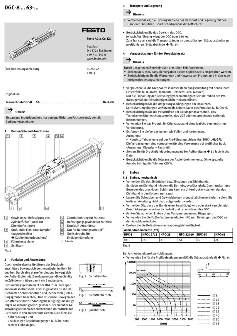
Festo DGC-8 Series User manual

Festo

Festo DGC-8 Series User manual

Festo CMMT-ST-C8-1C-...-S0 Series User manual

Festo

Festo CMMT-ST-C8-1C-...-S0 Series User manual

Festo DRRD Series User manual

Festo

Festo DRRD Series User manual

Festo DGO A-B Series User manual

Festo

Festo DGO A-B Series User manual

Festo CMMT-ST-SW User manual

Festo

Festo CMMT-ST-SW User manual

Festo DFPD-Series User manual

Festo

Festo DFPD-Series User manual

Festo DGC G Series Setup guide

Festo

Festo DGC G Series Setup guide

Festo DFPI-***-ND2P-C1V-***-A User manual

Festo

Festo DFPI-***-ND2P-C1V-***-A User manual

Festo DGC Series User manual

Festo

Festo DGC Series User manual

Festo EMCA-EC-67 CO Series Operating and installation instructions

Festo

Festo EMCA-EC-67 CO Series Operating and installation instructions

Festo DFPI ND2P-E-NB3P Series User manual

Festo

Festo DFPI ND2P-E-NB3P Series User manual

Festo DNG Series Setup guide

Festo

Festo DNG Series Setup guide

Festo EMCA-EC-67 CO Series Reference guide

Festo

Festo EMCA-EC-67 CO Series Reference guide

Festo DFPI-...D2P-C1V-NB3P series User manual

Festo

Festo DFPI-...D2P-C1V-NB3P series User manual

Festo DGCI Series User manual

Festo

Festo DGCI Series User manual

Festo DGC-8 Series User manual

Festo

Festo DGC-8 Series User manual

Festo DAPS Series User manual

Festo

Festo DAPS Series User manual

Festo ERMO User manual

Festo

Festo ERMO User manual

Festo ELGL-LAS User manual

Festo

Festo ELGL-LAS User manual

Festo EMCA-EC-67 CO Series Operating and installation instructions

Festo

Festo EMCA-EC-67 CO Series Operating and installation instructions

Festo DSM-6 User manual

Festo

Festo DSM-6 User manual

Festo DFPD-HD-RD Series Parts list manual

Festo

Festo DFPD-HD-RD Series Parts list manual

Festo DGC-HD Series Parts list manual

Festo

Festo DGC-HD Series Parts list manual

Popular DC Drive manuals by other brands

schmalenberger 27217-A Operator's manual

schmalenberger

schmalenberger 27217-A Operator's manual

REXROTH Fv Series instruction manual

REXROTH

REXROTH Fv Series instruction manual

Siemens SINAMICS S120 manual

Siemens

Siemens SINAMICS S120 manual

BONFIGLIOLI Vectron ACTIVE CUBE Applications manual

BONFIGLIOLI Vectron

BONFIGLIOLI Vectron ACTIVE CUBE Applications manual

Danfoss vlt fcd 302 Design guide

Danfoss

Danfoss vlt fcd 302 Design guide

YASKAWA HV600 Installation & Startup

YASKAWA

YASKAWA HV600 Installation & Startup

Lenze 8100 A Series Technical description

Lenze

Lenze 8100 A Series Technical description

Eurotherm Drives 590 DRV Digital product manual

Eurotherm Drives

Eurotherm Drives 590 DRV Digital product manual

elero RolTop-915 Operating and installation instructions

elero

elero RolTop-915 Operating and installation instructions

Trane TR200 Series operating instructions

Trane

Trane TR200 Series operating instructions

LS Starvert SV-iC5 Easy start guide

LS

LS Starvert SV-iC5 Easy start guide

olympia electronics BS-164 quick start guide

olympia electronics

olympia electronics BS-164 quick start guide

ABB ACS880-01 Series Quick installation guide

ABB

ABB ACS880-01 Series Quick installation guide

eldoLED LINEARdrive 720D quick start guide

eldoLED

eldoLED LINEARdrive 720D quick start guide

Trinamic PANdrive PD-1140 Hardware manual

Trinamic

Trinamic PANdrive PD-1140 Hardware manual

nord NORDAC SK 200E troubleshooting guide

nord

nord NORDAC SK 200E troubleshooting guide

Rhymebus RM6S2 Series Parameter manual

Rhymebus

Rhymebus RM6S2 Series Parameter manual

TPC SIMUTECH SIMVFD user manual

TPC

TPC SIMUTECH SIMVFD user manual

manuals.online logo
manuals.online logoBrands
  • About & Mission
  • Contact us
  • Privacy Policy
  • Terms and Conditions

Copyright 2025 Manuals.Online. All Rights Reserved.