ERICH INDUSTRIES 610 Service manual

As with any mechanized equipment, do not install, operate or service this product unless you have
read and understand the safety section, warnings, installation and operating instructions contained in
this manual. Failure to do so could result in property damage, bodily injury or even death.
- WARNING -
Rev. 01/01/13
MODEL 610 AND 310 AUTOMATIC DOOR OPERATORS
UTILIZED ON FLEXIBLE AND SOLID SELF-CLOSING TRAFFIC DOORS
Erich Industries, Inc.
Performance Products Division
550 N. Nine Mound Road
Verona, WI 53593
1-800-882-5839
U.S. Patent #4365-442
U.S. Patent #6138-412
Other Patents Pending
Misc. U.S. Trademarks
• Parts
• Technical
• Sales
• Support
SwingDoorOpeners.com

DETAILS FOR STANDARD PUSH (HEADER) MOUNT CONFIGURATION
NOTE: Roller track is not required or
supplied with 310 or 610 models.

SAFETY DETAILS

Step 2. Install floor mounted stops, if required and supplied, using hardware provided. See figure #2 below for details.
Step 1. Read and understand all directions prior to installation. Install door(s) if required and be sure
they travel freely with the standard spring or V-cam closers operating properly.
Model 610 and 310 Automatic Door Opener
Installation Instructions

Model 610 and 310 Mounting Detail
(angled arm version illustrated)

WARNING - Improper or inadequate
installation could result in premature
product wear or failure and could then
cause property damage, bodily injury
or even death.
or template #15043.
Step 3.
Step 4.
Mount control box to wall using template #14671 with unit mounted adjacent to openers or within 25'. For
distances greater than 25', please contact the factory for assistance.
TIP: As you would with all delicate instruments
and tools, preserve your openers finish by
maintaining the protective oil coating on all
metal bracket components.

REMINDER - Don't forget to mount
the "CAUTION Automatic Door"
stickers on the door(s)!
Step 9.
Follow wiring details and microprocessor programming next in accordance with specifics of your
particular application. Note that typical functions are pre-programmed at the factory so you may not need
to adjust at all. Then move on to the door speed control page before operating.
Example
Step 5.
Step 7.
Step 8.
Step 6.
Install adjustable swivel flow controls to each end of the air cylinder(s). Utilize previous mounting detail
drawing (two pages back) for air line attachment locations.
TIP - If you're opening a single door use the supplied plugs to cap one of the "open"
and "close" air ports.
E-HDEB
Optional sensor extension
bracket. Part # E-HDEB

Erich Industries, Inc.
AIR FORCE®AND DOOR DYNAMICS®DOOR OPENER
ELECTRICAL WIRING DETAILS
Our control box is microprocessor based to insure maximum reliability and flexibility for the user. The system
has been designed to be easy to set up and operate. Directions for setting the proper program are in the Circuit
Board User’s Manual located elsewhere in this manual. The control unit is designed to be connected to a
constant power source of 110VAC 60HZ or 230VAC 50HZ, which powers the control box and a wide variety of
activation devices with 24VAC power.
Activating devices and input signals should be connected directly to the terminal strip located on the left side of
the control board.
N = Power Common Lead
N = Power Common Lead
U = Unused - Auxiliary
R = Remote Proof of Closure Signal
S = Safety Signal
I = Initiate Signal
#1 = Unused - Auxiliary
#2 = Unused - Auxiliary
E = Unused - Auxiliary
D = Safety Signal
F = Fire Signal
P = Proof of Closure Switch Signal
H = 24V Power
H = 24V Power
Notes: Use Terminal strip connection to N and F to lock out opening if maglock is used and active. Door will
remain in open position if receiving input from terminal strip D or S regardless of input from activation device.
Below we provide wiring details for a variety of activation and safety devices available from Erich Industries. In
most cases other manufacturer’s models can also be wired to the system in a similar fashion. Please consult with
the manufacturer of that particular unit with questions or call us.
E-2005 MS Sedco microStar Motion Detector E-3090 MS Sedco DH400 Presence Sensor
Red to H Red to H
White to N Black to N
Brown to I Yellow to S
Black to N White to N
E-3060 MS Sedco GD11S Photoeye Safety Beam E-5010 MS Sedco 216 Touchless Switch
Transmitter: White to H Red to H
Black to N Green to N
Receiver: White to H Red to N
Black to N Blue to I
Gray to D
Green to N
E-3070 BEA Microcell Photoeye Safety Beam E-5020 BEA MS-08 Touchless Switch
#1 to H Red to H
#2 to N Black to N
#3 to D White to N
#4 to N Green to I
Cont.
TIP: If you require
replacement door
sensors go to
DoorSensors.com

E-4020 MS Sedco 99 Push Plate E-6010 VEE CP1 Pull Cord
Normally Open to I Normally Open to I
Common to N Common to N
MS Sedco 614 Piezo Switch MS Sedco DH94 Presence Sensor
Normally Open to I Red to H
Common to N Black to N
Yellow to S
White to N
BEA IS40 and IS40P Sensors E-5030 BEA MS21 Touchless Switch
Red to H Red to H
Black to N Black to N
White to N Green to I
Green to I White to N
White/Black to N Green/yellow to Earth Ground
Green/Black to S (for safety with lockout)
E-5040 BEA MS09 Touchless Switch E-5050 BEA MS11 Touchless Switch
Red to H Red to H
Black to N Black to N
White to N Green to I
Green to I White to N
E-5060 Piezo Push Button Switch E-1010-1EX Explosion Proof Push Button
Plus to H Normally Open to I
Minus to N Common to N
Com1 to N
Normally Open to I
Additional questions can typically be answered by calling the factory technical support staff at
1-800-882-5839.
Revision 01/01/19

Erich Industries, Inc.
Performance Products Division
Automatic Door Opener
Erich Industries, Inc.

Erich Industries, Inc.
NOTE: Most functions are pre-programmed at the
factory so no adjustments may be required here.
Then simply utilize this section for future reference.


Erich Industries, Inc.


NEVER adjust regulators beyond 85 PSI or any
setting that is safe! Door speed will vary depending
on weight of door and any air pressures.
Final Step. Adjust all activating and safety devices in accordance with the manufacturers instructions
and owners preferences.
NOTE: Flexible traffic style doors are typically
light and will most likely require lower settings
of the air regulator and door speed controls.
Start low with PSI adjustments and work up
then fine tune the door movement with the
small flow control knob adjustments mounted
on the cylinder(s).

25 Section 4 - Operation
Erich Industries Performance Products Division Phone 800/305-6736
550N.NineMoundRoad
Verona,WI 53593
OPERATING PROCEDURES FOR OPENERS
A) Start-up(refer toinstallationinstructions fordetails)
1. Make sureairlineshavebeen purged(blownfree ofparticles inairline) priortosupplyline
hook-upto controlenclosure. Attach supplylinetocontrolenclosure.
2. Plug incord orhardwire toelectric (110volt) sourcesinaccordance withlocal codes.
3. Depress ON-OFF switch to turn on.
4. Set activatingdevicesto owner’srequirements.
5. Adjustopening speedwith airpressure controlknob incontrol enclosure. Neverlower more
than 40 PSI or raise higher than 85 PSI.
6. Doorshould not slamopen or closed. If thisoccurs, increase the backcheck on thedoor
closerto a cushioned stopat the end ofthe cycle. Adjust thelatchcheck on thecloser for a
cushionedcloseattheend ofthe closingcycle.
B) Operation
1. Depress ON-OFF switch to activate door operator and turn on.
2. Release ON-OFFswitchto de-activate door operatorand turn off.
3. Allactivatingdevicesmustbepluggedintocontrolenclosuretofunction.
4. Operators willnot bedamaged ifheld inclosed oropen positionwhile activatedforanex-
tendedperiod oftime.
C) EmergencyOperation
1. Incase of apower outageorif turnedoff,the doorswill openandclose manually. Theopera-
torwillnot bedamagedwhen operatedmanually.
2. Always turnoperators offduring a poweroutage andturn onwhen powerisrestored.
D) Shutdown
1. Use ON-OFFswitch on thecontrolenclosure to de-activatethe operator. Turn off.
WARNING - Be sure all safety devices and
activators are working properly before putting into
service. If you are having any problem with these
devices, turn off the opener and contact the
manufacturer of the sensor or Erich Industries.
Model 610 and 310 Operating Procedures
IF THIS OCCURS REFER TO SPEED CONTROL PAGE OF THIS MANUAL.

26
Section 5 - Maintenance
Erich Industries Performance Products Division Phone 800/305-6736
550N. Nine Mound Road
Verona, WI 53593
MAINTENANCE PROCEDURES FOR “KWIK-OP”
A) Maintenance-AirSource (as applicable)
1. Service compressors,filters,etc. aspermanufacturer’sinstructions.
2. Service shouldbecarried outin3monthintervals,oras required. Consultthismanual for
details.
B) Maintenance-Operators
1. Manually opendoors to check for“freeswing”. Adjustand/or lubricatehinges.
2. Checkactuator armsforexcessive play. Ifrequired, loosenset screwor lock nutand tighten
bolttoremove play. Donotover tighten,whichwillcausebinding. After tighteningsetscrew
orlock nut,check againto insurethat theunit hasfree action.
3. Check cylinderjambnut andtighten(ifrequired)withthecylinder ventonthe bottom.
4. Lubricatebearingpointswith spraylube.
5. Checkair filteronsupplyairline. Clean, drain,or replaceas required.
6. Check,air hoses andconnections forleaks, kinks, orcontact with movingparts. Correct as
required.
7. Checkair pressureandopening speed. Adjustper instructionsasrequired.
8. Checkcloser back check,closing speed, andlatch speed. Adjust perinstructions as required.
9. CheckTimeDelay period. Adjustperinstructions asrequired.
10. Service shouldbecarriedoutin3month intervalsalongwithcompressor servicing,orasrequired.
If any parts are worn or need replacing, consult this manual for parts listing.
WARNING - Be sure all safety devices and
activators are working properly before putting into
service. If you are having any problem with these
devices, turn off the opener and contact the
manufacturer of the sensor or Erich Industries.
Model 610 and 310 Maintenance Procedures

WARNING - Be sure all safety devices
and activators are working properly before
putting into service. If you are having any
problem with these devices, turn off the
opener and contact the manufacturer of
the sensor or Erich Industries.
Troubleshooting

Model 610 and 310 Parts List
Exploded View
630 Model / 14787 300 Model
DD-3000
DD-3003
630 Model / 14964 300 Model
DD-3007A Flat Head Cap Screw
DD-3007A
DD-3033
DD-3032
DD-4000630 630 Model / DD-4001 300 Model Air Cylinder
DD-4000630
or DD-4001
300 Model
DD-7002 Universal
NOTE: Part numbers
detailed are for both the 310
and 610 models unless
noted otherwise. On some
parts obsolete and current
part numbers are shown for
reference purposes.
Required for
630 Model
DD-7004 Cylinder Bracket 630 / DD-7014 300 Model
DD-7004 630
DD7014 300
Included with Cylinders
DD-8526
DD-8527
DD-8526
DD-8527
DD-8505630
DD-8506630
Questions? 1-800-882-5839
14002
14002
Arm with
30
degree
bend (not
shown)
This manual suits for next models
1
Table of contents
Popular Garage Door Opener manuals by other brands

Chamberlain
Chamberlain LM50 Assembly and operating instructions
Linear
Linear LDC0801 Homeowner's instructions

Roger Technology
Roger Technology F70/IPU36 Instruction and warnings for the installer
Homentry
Homentry HERDO1 Installation and operating guide
Linear
Linear LD 033 Homeowner's instructions
Chamberlain
Chamberlain Whisper Drive WD822K owner's manual

Chamberlain
Chamberlain LM800A instructions
BFT
BFT EOS 120 VENERE D Installation and user manual
tau
tau SPIN Use and maintenance manual

Merlin
Merlin Commander Elite MS105MYQ Installation and operating instructions
Craftsman
Craftsman CMXEOCG781 owner's manual
Force Technology
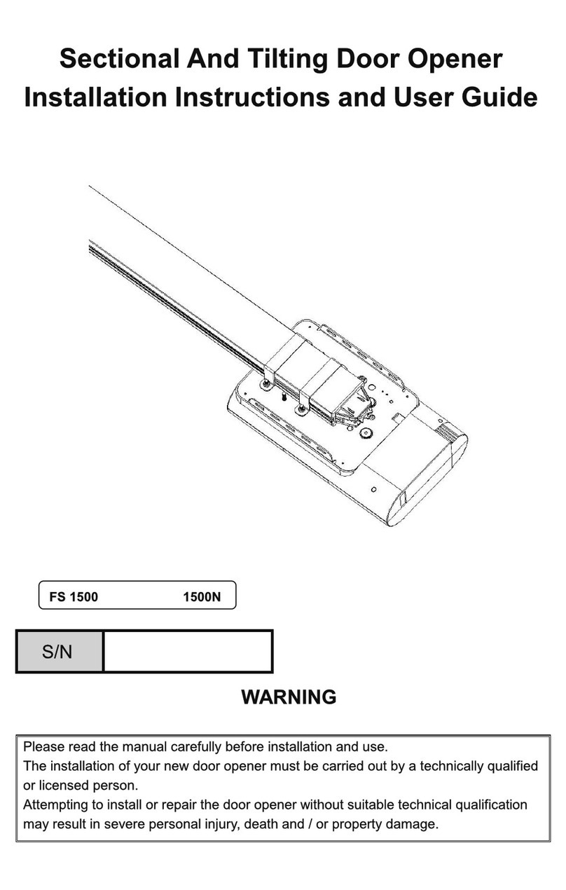
Force Technology FS 1500 Installation instructions and user guide
