manuals.online logo
Brands
  1. Home
  2. •
  3. Brands
  4. •
  5. Nice
  6. •
  7. Garage Door Opener
  8. •
  9. Nice ROBUS RB400 Product manual

Nice ROBUS RB400 Product manual

Other manuals for ROBUS RB400

3

This manual suits for next models

3

Other Nice Garage Door Opener manuals

Nice MhouseKit SL1W Installation and operating instructions

Nice

Nice MhouseKit SL1W Installation and operating instructions

Nice FILO Series Technical specifications

Nice

Nice FILO Series Technical specifications

Nice RD400 Technical specifications

Nice

Nice RD400 Technical specifications

Nice SPY800KCE/V1 Technical specifications

Nice

Nice SPY800KCE/V1 Technical specifications

Nice SO2000 Technical specifications

Nice

Nice SO2000 Technical specifications

Nice RONDO Series Technical specifications

Nice

Nice RONDO Series Technical specifications

Nice AVIO500 Technical specifications

Nice

Nice AVIO500 Technical specifications

Nice Mhouse PT50 Product manual

Nice

Nice Mhouse PT50 Product manual

Nice Spido Technical specifications

Nice

Nice Spido Technical specifications

Nice ROBUS RB250HS User manual

Nice

Nice ROBUS RB250HS User manual

Nice ROBUS RB400 Technical specifications

Nice

Nice ROBUS RB400 Technical specifications

Nice Soon User manual

Nice

Nice Soon User manual

Nice SHEL60KIT Technical specifications

Nice

Nice SHEL60KIT Technical specifications

Nice Spido User manual

Nice

Nice Spido User manual

Nice RUN1500 Technical specifications

Nice

Nice RUN1500 Technical specifications

Nice Road200 Product manual

Nice

Nice Road200 Product manual

Nice SPY SPY800KCE/V1/US01 User manual

Nice

Nice SPY SPY800KCE/V1/US01 User manual

Nice NICEONE OXI SERIES Product manual

Nice

Nice NICEONE OXI SERIES Product manual

Nice TUB4000 Technical specifications

Nice

Nice TUB4000 Technical specifications

Nice HySecurity SlideSmart DC Series Assembly instructions

Nice

Nice HySecurity SlideSmart DC Series Assembly instructions

Nice ALTO100C Technical specifications

Nice

Nice ALTO100C Technical specifications

Nice TN2010L Technical specifications

Nice

Nice TN2010L Technical specifications

Nice RO 1000 Guide

Nice

Nice RO 1000 Guide

Nice THOR Product manual

Nice

Nice THOR Product manual

Popular Garage Door Opener manuals by other brands

ATA GDO-6 EasyRoller instruction manual

ATA

ATA GDO-6 EasyRoller instruction manual

CAME F4000 Series installation manual

CAME

CAME F4000 Series installation manual

Garaga SECURITY+ 3265GCM 1HP owner's manual

Garaga

Garaga SECURITY+ 3265GCM 1HP owner's manual

Chamberlain Whisper Drive SECURITY+ WD822K Series owner's manual

Chamberlain

Chamberlain Whisper Drive SECURITY+ WD822K Series owner's manual

Chase Doors DuraShield installation manual

Chase Doors

Chase Doors DuraShield installation manual

CSI Classic installation instructions

CSI

CSI Classic installation instructions

Chamberlain Elite 3575S owner's manual

Chamberlain

Chamberlain Elite 3575S owner's manual

Richmond GTR156 user manual

Richmond

Richmond GTR156 user manual

B&D Controll-A-Door 5 instruction manual

B&D

B&D Controll-A-Door 5 instruction manual

Chamberlain MyQ 940ESTD owner's manual

Chamberlain

Chamberlain MyQ 940ESTD owner's manual

Automatic Technology GDO-9V1 SecuraLift installation instructions

Automatic Technology

Automatic Technology GDO-9V1 SecuraLift installation instructions

Westfalia 19 36 07 instruction manual

Westfalia

Westfalia 19 36 07 instruction manual

Chamberlain HD520EVP manual

Chamberlain

Chamberlain HD520EVP manual

Cardin BL Series instruction manual

Cardin

Cardin BL Series instruction manual

Chamberlain 8355 - 1/2 hp installation instructions

Chamberlain

Chamberlain 8355 - 1/2 hp installation instructions

Bauer CROSS18 Application. Installation and Maintenance Manual

Bauer

Bauer CROSS18 Application. Installation and Maintenance Manual

Dorma ES 90 manual

Dorma

Dorma ES 90 manual

Wayne-Dalton 8124 Installation instructions and owner's manual

Wayne-Dalton

Wayne-Dalton 8124 Installation instructions and owner's manual

manuals.online logo
manuals.online logoBrands
  • About & Mission
  • Contact us
  • Privacy Policy
  • Terms and Conditions

Copyright 2025 Manuals.Online. All Rights Reserved.

Run
Sliding Gate Opener
RUN1500
Instructions and warnings for the fitter
This manual is not for the inverted
2500Imodel
RUN 1500
EN - Integration to manual
Robus 600-1000
IT - Integrazione al manuale
Robus 600-1000
FR - Addenda au guide
Robus 600-1000
ES - Integración del manual
Robus 600-1000
DE - Vervollständigung des
Handbuchs Robus 600-1000
PL - Uzupełnienie do instrukcji
Robus 600-1000
NL - Aanvulling op de handleiding
Robus 600-1000
RB400 - RUN1500
For sliding gates
Codice: ISTRB2A.4865 Rev. 01 del 22 - 06 - 2009
DICHIARAZIONE CE DI CONFORMITÀ / CE DECLARATION OF CONFORMITY
Nota - Il contenuto di questa dichiarazione corrisponde a quanto dichiarato nell’ultima revisione disponibile, prima della stampa di questo manuale, del documento ufficiale deposi-
tato presso la sede di Nice Spa. Il presente testo è stato riadattato per motivi editoriali. / Note - The contents of this declaration correspond to those of the last revision available
of the official document, deposited at the registered offices of Nice S.p.a., before printing of this manual. The text herein has been re-edited for editorial purposes.
Numero / Number: 210/ROBUS Revisione / Revision:2
Il sottoscritto Luigi Paro in qualità di Amministratore Delegato, dichiara sotto la propria responsabilità che il prodotto: / The undersigned Luigi Paro, managing director, declares
under his sole responsibility that the following product:
Nome produttore / Manufacturer’s name: NICE s.p.a.
Indirizzo / Address: Via Pezza Alta 13, 31046 Z.I. Rustignè, Oderzo (TV) Italia / Italy
Tipo / Type: Motoriduttore elettromeccanico con centrale incorporata / Ac electromechanical gearmotor with built-in control unit
Modello / Models: RB600, RB600P, RB1000, RB1000P, RB400KIT, RUN1500
Accessori / Accessories: Ricevente radio SMXI, SMXIS; batteria di emergenza PS124 /Radio receiver SMXI, SMXIS; buffer battery PS124
Risulta conforme a quanto previsto dalla direttiva comunitaria: / Satisfies the essential requirements of the following Directives:
• 98/37/CE (89/392/CEE modificata) / 98/37/EC (89/392/EEC amended).
Come previsto dalla direttiva 98/37/CE si avverte che non è consentita la messa in servizio del prodotto sopra indicato finché la macchina, in cui il prodotto è incorporato, non sia
stata identificata e dichiarata conforme alla direttiva 98/37/CE / As specified in the directive 98/37/CEE use of the product specified above is not admitted until the machine on
which it is mounted has been identified and declared as conforming to the directive 98/37/CEE.
Inoltre il prodotto risulta conforme a quanto previsto dalle seguenti direttive comunitarie, così come modificate dalla Direttiva 93/68/CEE del consiglio del 22 Luglio 1993: / Further-
more, the product complies with the specifications of the following EC directives:
• 2006/95/CEE(ex direttiva 73/23/CE) . / 2006/95/EEC (ex directive 73/23/EC).
Secondo le seguenti norme armonizzate: / According to the following harmonised standards: EN 60335-1:1994+A11:1995+A1:1996+A13:1998
+A14:1998+A15:2000+A2:2000+A16:2001
• 2004/108/CEE(ex direttiva 89/336/CEE) / 2004/108/EEC (ex directive 89/336/EEC).
Secondo la seguente norma armonizzata: / According to the following harmonised standards:
EN 61000-6-2:2001; EN 61000-6-3:2007
Inoltre risulta conforme, limitatamente per le parti applicabili, alle seguenti norme: / Furthermore, complies with the specifications, limitedly for the applicable the following standards:
EN 60335-1:2002+A1:2004+A11:2004+A12:2006+ A2:2006, EN 60335-2-103:2003, EN 13241-1:2003; EN 12453:2002; EN 12445:2002; EN 12978:2003
Oderzo, 8 Maggio 2009 / Oderzo, 8 May 2009 Luigi Paro
(Amministratore Delegato / Managing Director)
This Addendum provides the specific data of products RB400 and RUN1500; tables 2 and 3 also contain data specified in the reference
manual of the product Robus 600-1000.
APPLICATION LIMITS: in general, RB400 is designed for the automation of gates with weights up to 400 Kg and lengths up to 7 m,
while RUN1500 is designed for the automation of gates with weights up to 1500 Kg and lengths up to 14 m; see table 1 and 2.
The length of the leaf enables the calculation of the maximum number of cycles per hour and the maximum number of consecutive cycles,
while the weight enables calculation of the percentage of reduction in the number of cycles at the maximum admissible speed.
Table 2: limits in relation to the leaf length
ENGLISH
Leaf length (m) maximum cycles/hour maximum consecutive cycles
RB400 RB600 RB1000 RUN1500 RB400 RB600 RB1000 RUN1500
Up to 4 35 40 50 60 14 20 25 30
4 - 6 23 25 33 40 11 13 16 20
6 - 7 20 23 28 34 10 11 14 17
7 - 8 - 20 25 30 - 10 12 15
8 - 10 - - 20 24 - - 10 12
10 - 12 - - 16 20 - - - 10
12 - 14 - - - 17 - - - 8
TECHNICAL SPECIFICATIONS
RB400 RB600-RB600P RB1000-RB1000P RUN1500
Pinion Z: 15; Pinion Z: 15; Module: 4; Pinion Z: 18,
Module: 4; Pitch: 12,6 mm; Module: 4;
Pitch: 12,6 mm; Primitive diameter: 60 mm Pitch: 12.6 mm;
Primitive Primitive
diameter: 60 mm diameter: 72 mm
12 Nm 18 Nm 27 Nm 35 Nm
[400 N] [600 N] [900 N] [1000 N]
6 Nm 9 Nm 15 Nm 20 Nm
[200 N] [300 N] [500 N] [560 N]
0,18 m/s 0,15 m/s 0,14 m/s 0,18 m/s
0,34 m/s 0,31 m/s 0,28 m/s 0,25 m/s
35 40 50 60
The control unit limits the number of cycles tothe maximum value as stated in tables 2 and 3
10 minutes
In general Robus and Run are designed for the automation of gates with
weights and lengths within the limits specified in tables 2, 3 and 4
330 W 515 W [2,5 A] 450 W [2,3 A] 400 W
[4,8 A version/V1] [4,4 A version/V1]
330 x 195 h 277 330 x 120 h 303 330 x 210 h 303 400 x 255 h 390
8 Kg 11 Kg 13 Kg 19 Kg
Table 3: limits in relation to the leaf weight
Leaf weight (kg) percentage of cycles maximum admissible speed
RB400 RB600 RB1000 RUN1500 RB400 RB600 RB1000 RUN1500
Up to 200 100% 100% 100% 100% V6 V6 V6 V6
200 - 400 50% 80% 90% 100% V5 V5 V5 V6
400 - 500 - 60% 60% 95% - V4 V4 V6
500 - 600 - 50% 100% 90% - V3 V4 V5
600 - 700 - - 50% 85% - - V3 V5
700 - 800 - - 47% 80% - - V3 V5
800 - 900 - - 45% 75% - - V3 V5
900 - 1000 - - 40% 70% - - V3 V4
1000 - 1200 - - - 60% - - - V4
1200 - 1350 - - - 65% - - - V3
1350 - 1500 - - - 60% - - - V3
MODEL:
Pinion
Maximum start-up torque
[corresponding to the capacity to generate a
set force to move the gate leaf]
Nominal torque
[corresponding to the capacity to generate a
set force to move the gate leaf]
Speed at nominal torque
Speed under no load
(the control unit enables programming of six
speeds at approx.: 100, 85, 70, 55, 45, 30%)
Maximum frequency of cycles per hour of
operation
[on a standard gate of 4 m]
Maximum continuous operation time
Application limits
Maximum power absorption on start-up
[corresponding to Amps]
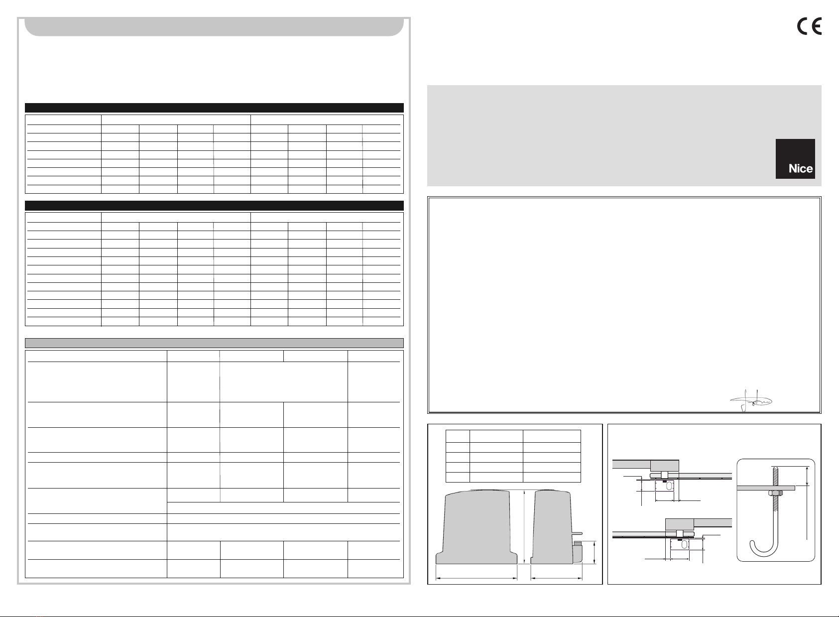
Dimensions (mm) and weight
RUN1500
RB400 RUN1500
a330 mm 400 mm
b277 mm 390 mm
c195 mm 255 mm
d85 mm 108 mm
ac
b
d
400 0÷50
0÷10
240
4000÷50
0÷10
240
max. 40 mm
3
GB
1) Warnings
This manual contains important information regarding safety. Before
starting installation of the components, it is important that you read all
the information contained herein. Store this manual safely for future use.
Due to the dangers which may arise during both the installation and use
of the RUN, installation must be carried out in full observance of the
laws, provisions and rules currently in force to ensure maximum safety.
This chapter provides details of general warnings. Other more specific
warnings are detailed in Chapters “3.1 Preliminary Checks” and “5 Test-
ing and Commissioning”.
According to the most recent European legislation, the
automation of doors or gates is governed by the provisions
listed in Directive 98/37/CE (Machine Directive) and, more
specifically the standards: EN 13241-1 (harmonised stan-
dard); EN 12445; EN 12453 and EN 12635, which enables the
declaration of machine conformity to the machine directive.
Visit “www.niceforyou.com” for further information and guidelines for risk
analysis and how to draw up the Technical Documentation. This manu-
al has been especially written for use by qualified fitters. Except for the
enclosed specification “Instructions and Warnings for Users of the RUN
gearmotor” to be removed by the installer, none of the information pro-
vided in this manual can be considered as being of interest to the end
users!
• Any use or operation of RUN not explicitly provided for in these instruc-
tions is not permitted. Improper use may cause damage and person-
al injury.
• A risk analysis must be carried out before starting installation, includ-
ing a the list of essential safety requisites provided for in Enclosure I of
the Machine Directive, indicating the relative solutions employed. N.B.
Risk analysis is one of the documents included in the “Technical Doc-
umentation” for this automation.
• Check whether additional devices are needed to complete the
automation with RUN based on the specific application requirements
and dangers present. The following risks must be considered: impact,
crushing, shearing, dragging, etc. as well as other general dangers.
• Do not modify any components unless such action is specified in this
manual. Operations of this type are likely to lead to malfunctions. NICE
disclaims any liability for damage resulting from modified products.
• During installation and use, ensure that solid objects or liquids do not
penetrate the control unit or other open devices. If necessary, contact
the NICE customer service department; use of RUN in these condi-
tions can be dangerous.
• The automation system must not be used until it has been commis-
sioned as described in chapter 5 “Testing and commissioning”.
• The RUN packaging materials must be disposed of in compliance with
local regulations.
• If a fault occurs that cannot be solved using the information provided
in this manual, contact the NICE customer service department.
• In the event that any automatic switches are tripped or fuses blown,
attempt to identify and eliminate the relative fault.
• Disconnect all the power supply circuits before accessing the terminals
inside the RUN cover. If the disconnection device is not identifiable,
affix the following sign: “WARNING: MAINTENANCE WORK IN
PROGRESS”.
Special warnings concerning the suitable use of this product in relation
to the 98/37CE “Machine Directive” (ex 89/392/CEE):
• This product is issued on the market as a “machine component” and
is therefore manufactured to be integrated in a machine or assembled
with other machines in order to create “a machine”, in accordance with
the directive 98/37/EC, exclusively in combination with other compo-
nents and in the manner described in the present instructions manual.
As specified in the directive 98/37CE the use of this product is not
admitted until the manufacturer of the machine on which this product
is mounted has identified and declared it as conforming to the directi-
ve 98/37/CE.
Special warnings concerning suitable use of this product in relation to
the 73/23/EEC “Low Voltage” Directive and subsequent amendments
93/68/CEE:
• This product complies with the provisions envisaged by the “Low Vol-
tage” Directive if used in the configurations foreseen in this instruction
manual and in combination with the articles present in the Nice S.p.a.
product catalogue. If the product is not used in the specified configu-
rations or is used with other products that have not been foreseen, the
requirements may not be guaranteed; use of the product is prohibited
in these conditions until compliance with the requirements foreseen by
the directive has been verified by installers.
Special warnings concerning suitable use of this product in relation to
the 89/336/EEC “Electromagnetic Compatibility” Directive and subse-
quent amendments 92/31/EEC and 93/68/EEC:
• This product has undergone tests regarding electromagnetic compati-
bility in the most critical of use conditions, in the configurations fore-
seen in this instruction manual and in combination with articles present
in the Nice S.p.A. product catalogue. Electromagnetic compatibility
may not be guaranteed if used in configurations or with other products
that have not been foreseen; use of the product is prohibited in these
conditions until compliance with the requirements foreseen by the
directive has been verified by installers.
!
4
RUN is a range of irreversible electromechanical gearmotors used for
the automation of sliding gates. They are equipped with an electron-
ic control unit and an “SM” type connector for radio control receivers
(optional ). Electrical connections to external devices are facilitated
thanks to the use of the “BlueBUS” system, which enables the con-
nection of several devices by means of just 2 wires. The list of
devices compatible for connection to the Run BlueBUS is given in
chapter 7.3.1 "BlueBUS"; an updated list, with relative compatibility
is also available at: www.niceforyou.com. RUN is equipped with a
connector for remote programming units to enable complete and
quick management of installation, maintenance, troubleshooting of
any malfunctions; refer also to 7.8.1 "Remote programming unit".
RUN is electrically powered, in the event of a power failure, the
device can be released by means of the special key, to enable man-
ual movement of the gate.
Other products are also part of the RUN range, the difference of which is described in table 1.
Note: 1Kg = 9,81N for example: 1390N = 142 Kg
2) Product description and applications
1
Gearmotor type
Limit switch type electromechanical
Maximum leaf length 15m
Maximum leaf weight 1500Kg
Peak thrust 40Nm
(corresponding to a force) (1110N)
Table 1: comparison of the RUN gearmotor main characteristics
2.1) Operating limits
Chapter 8 “Technical Characteristics” provides the only data needed
to determine whether the products of the RUN line are suitable for
the intended application. The structural characteristics of RUN make
it suitable for use on sliding leaves in conformity with the limits spec-
ified in tables 2, 3 and 4.
The effective suitability of RUN to automate a sliding gate depends
on friction and other factors, even occasional, such as the presence
of ice which could obstruct leaf movement. To ensure suitability, it is
absolutely vital to measure the force necessary to move the leaf
throughout its entire run and ensure that this is less than half of the
“nominal torque” indicated in chapter 8 “Technical characteristics” (a
50% margin on the force is recommended, as unfavourable climatic
conditions may cause an increase in the friction); furthermore, the
data specified in tables 2 and 3 should be taken into account to
establish the number of cycles/hour and consecutive cycles.
RUN1500
Leaf width(m) max. cycles/hour
Upto6
6÷9
9 ÷ 12 21
12 ÷ 15 17
15 ÷ 18 17
Table 2: limits in relation to the length of the leaf
400mm 253mm
387mm
108mm
RUN1500
60
34
6
2.2) Typical system
Figure 2 shows a typical system for automating a sliding gate using RUN.
2
1Key-operated selector switch
2Receiver FT210B
3Photocells
4Transmitter FT210B
5Primary movable edge
6“Open” limitswitch bracket
7Rack
8Flashing light with incorporated aerial
9RUN
10 “Closed” limitswitch bracket
11 Primary movable edge (optional)
12 Radio transmitter
2.3) List of cables
The typical system shown in figure 2 also states the cables required for connection of the various devices, the specifications of which are
provided in table 5.
The cables used must be suitable for the type of installation; for example, an H03VV-F type cable is recommended for indoor
applications, while H07RN-F is suitable for outdoor applications.
!
Note 1: power supply cable longer than 30 m may be used provided it has a larger gauge, e.g. 3x2,5mm2, and that a safety earthing sys-
tem is provided near the automation unit.
Note 2: If the “BLUEBUS” cable is longer than 30 m, up to 50 m, a 2x1mm2cable is needed.
Note 3: A single 4x0,5mm2cable can be used instead of two 2x0,5mm2cables.
Note 4: Refer to Chapter “7.3.2 STOP Input” in situations where there is more than one edge, for information about the type of connection
recommended by the manufacturer.
Note 5: special devices which enable connection even when the leaf is moving must be used to connect movable edges to sliding leaves;
con l'anta in movimento; nella figura è indicato l'utilizzo di FT210B.
Connection Cable type Maximum admissible length
A: Electrical power line N°1 cable 3x1,5mm230m (note 1)
B: Flashing light with aerial N°1 cable 2x0,5mm220m
N°1 shielded cable type RG58 20m (less than 5m recommended )
C: Photocells N°1 cable 2x0,5mm230m (note 2)
D: Key-operated selector switch N°2 cable 2x0,5mm2(note 3) 50m
E:
Connection between 2 movable edges
N°1 cable 2x0,5mm2(note 4) 20m
F: Movable edge connection N°1 cable 2x0,5mm2(note 5) 30m
Table 5: List of cables
2
338
FB9C
6
10
7
12
115E1
CF 4
DA
7
GB
3.2) Installation of the gearmotor
The gearmotor must be secured directly to an already existing
mounting surface using suitable means, for example expansion
bolts. Otherwise, in order to fasten the gearmotor the installer must:
1. Dig a foundation hole with suitable dimensions referring to Figure 3.
2. Prepare one or more conduits for the electrical cables as shown
in figure 4.
3. Assemble the 4 clamps on the foundation plate setting one nut
underneath and one on top of the plate. The nut underneath the
plate must be tightened as shown in Figure 5 so that the thread-
ed part protrudes above the plate by max. 40 mm.
4. Pour the concrete and, before it starts to harden, set the founda-
tion plate to the values shown in Figure 3. Check that it is paral-
lel to the leaf and perfectly level (Figure 6). Wait for the concrete
to harden completely.
5. Remove the 4 upper nuts on the plate and then position the gear-
motor. Check that it is perfectly parallel to the leaf, then refit and
tighten the four nuts and washers supplied, as shown in Figure 7.
The installation of RUN must be carried out by qualified personnel in compliance with current legislation, standards and
regulations, and the directions provided in this manual.
!
3) Installation
3.1) Preliminary checks
Before proceeding with the installation of RUN:
• Check that all the materials are in excellent condition, suitable for
use and compliant with current standards.
• Ensure that the structure of the gate is suitable for automation.
• Ensure that the weight and dimensions of the leaf fall within the
specified operating limits provided in chapter “2.1 Operating limits”.
• Check that the force required to start the movement of the leaf is
less than half the “maximum torque”, and that the force required to
keep the leaf in movement is less than half the “nominal torque”.
Compare the resulting values with those specified in Chapter “8
Technical Characteristics”. The manufacturers recommend a 50%
margin on the force, as unfavourable climatic conditions may
cause an increase in the friction.
• Ensure that there are no points of greater friction in the opening or
closing travel of the gate leaves.
• Ensure there is no danger of the gate derailing.
• Ensure that the mechanical stops are sufficiently sturdy and that
there is no risk of deformation even when the leaf hits the mechan-
ical stop violently.
• Ensure that the gate is well balanced: it must not move by itself
when it is placed in any position.
• Ensure that the area where the gearmotor is fixed is not subject to
flooding. If necessary, mount the gearmotor raised from the
ground.
• Ensure that the installation area enables the release of the gear-
motor and that it is safe and easy to release it.
• Ensure that the mounting positions of the various devices are pro-
tected from impact and that the mounting surfaces are sufficiently
sturdy.
• Components must never be immersed in water or other liquids.
• Keep RUN away from heat sources and open flames; in acid,
saline or potentially explosive atmosphere; this could damage RUN
and cause malfunctions or hazardous situations.
• If there is an access door in the leaf, or within the range of move-
ment of the gate, make sure that it does not obstruct normal trav-
el. Mount a suitable interlock system if necessary.
• Only connect the control unit to a power supply line equipped with
a safety grounding system.
• The power supply line must be protected by suitable magneto-
thermal and differential switches.
• A disconnection device must be inserted in the power supply line
from the electrical mains (the distance between the contacts must
be at least 3.5 mm with an overvoltage category of III) or equiva-
lent system, for example an outlet and relative plug. If the discon-
nection device for the power supply is not mounted near the
automation, it must have a locking system to prevent unintention-
al, unauthorised connection.
3
45
6
Max. 40mm
7
400 0÷50
0÷50 400
240 0÷10
240 0÷10
8
3.3) Fixing of the limit switch bracket on versions with inductive limit switch
8.
Slide the leaf, using the pinion as a reference point for the securing
the other elements of the rack.
9.
Cut away the excess section of the rack.
10.
Open and close the gate several times and make sure that the rack
is aligned with the pinion with a maximum tolerance of 5 mm. More-
over, check that the play of 1÷2 mm has been respected along the
entire length between the pinion and the rack.
11.
Thoroughly tighten the two fixing nuts of the gearmotor making
sure it is well secured to the ground. Cover the fixing nuts with the
relative caps as shown in figure 10.
12.
Fix the limit switch bracket as described below (for versions
RUN1800P and RUN2500P, fix the bracket as described in para-
graph “3.3 Fixing of the limit switch bracket on versions with induc-
tive limit switch”):
• Manually place the leaf in the open position leaving at least 2-3
cm from the mechanical stop.
• Slide the bracket along the rack in the opening direction until the
limit switch cuts-in. Then bring the bracket forward by at least 2
cm and secure it to the rack with the appropriate stud bolts, as
shown in fig. 11.
• Perform the same operation for the closure limit switch.
13.
Secure the gearmotor as described in the paragraph “Release and
manual movement” in the Chapter “Instructions and Warnings for
Users”.
8 9
10 11
6. Release the gearmotor as shown in “Release and manual move-
ment” paragraph in the Chapter “Instructions and Warnings for
users of the RUN gearmotor”.
7. Open the leaf up completely and place the first piece of the rack
on the pinion. Check that the beginning of the rack corresponds
to the beginning of the leaf, as shown in Figure 8. Leave 1÷2 mm
play between the rack and the pinion, then fasten the rack to the
leaf using suitable means.
In order to prevent the weight of the leaf from affecting
the gearmotor, it is important that there is a play of 1÷2
mm between the rack and the pinion as shown in Figure 9.
!
1÷2mm
The limit switch bracket must be fixed as described below for the
RB600P and RB1000P versions that utilise the inductive limit switch.
1. Manually place the leaf in the open position leaving at least 2-3
cm from the mechanical stop.
2. Slide the bracket along the rack in the opening direction until the
corresponding LED switches off, as in fig. 12. Then bring the
bracket forward by at least 2 cm and secure it to the rack with the
appropriate stud bolts.
3. Manually place the leaf in the closed position leaving at least 2-3
cm from the mechanical stop.
4. Slide the bracket along the rack in the closing direction until the
corresponding LED switches off. Then bring the bracket forward
by at least 2 cm and secure it to the rack with the appropriate
stud bolts.
Warning: the ideal distance of the bracket for inductive
limit switches is between 3 and 8 mm as indicated in fig. 13.
!
12
13
3÷8mm
9
GB
3.5) Electrical connections
Only carry out electrical connections once the electric-
ity supply to the system has been switched off.
1. Remove the protection cover in order to access the electronic
control unit of the RUN. The side screw must be removed, and
the cover lifted upwards.
2. Remove the rubber membrane sealing off the two holes for routing
the cables; insert the power cable in the smaller hole and all other
cables for the various devices in the larger hole, leaving a length of
20÷30 cm longer than necessary. See Table 5 for information
regarding the type of cables and Figure 2 for the connections.
3. Use a clamp to collect together and join the cables routed through
the larger hole and place the clamp under the cable entry hole.
Make a hole in the rubber membrane which is slightly smaller than
the diameter of the cables joined by the clamp, and slide the
membrane along the cables until it reaches the clamp. Then put
the membrane back in its seat. Place a second clamp for collect-
ing the cables which are set just above the membrane.
4. On the smaller membrane, cut a hole slightly smaller than the
diameter of the power cable and slide the membrane along the
cable until it fits into its seat.
5. Connect the power cable to the relative terminal as shown in fig-
ure 14, and secure the cable by means of the collar.
6. Connect up the other cables according to the diagram in Figure 16.
The terminals can be removed in order to facilitate this procedure.
7. Once the connections have been completed, secure the cables
joined in the clamps to the cable locking rings. The excess aerial
cable must be secured to the other cables using another clamp as
shown in Figure 15.
!
3.4) Installation of the various devices
If other devices are required, install them following the directions provided in the corresponding instructions. Check this in paragraph “3.6
Description of electrical connections” and the devices which can be connected to the RUN in Figure 2.
14
16
15
See paragraph “7.3.5 RUN in Slave mode” for the connection of 2 motors on opposite leaves.
LUCYB
S.C.A.
MOFB MOSE
OPEN CLOSE
10
3.6) Description of the electrical connections
The following is a brief description of the electrical connections; for
further information please read “7.3 Adding or Removing Devices”
paragraph.
FLASH: output for one or two “LUCYB” or similar type flashing
lights with single 12V maximum 21W bulb.
S.C.A.: “Open Gate Light” output. An indication lamp can be con-
nected (24V max. 4W). It can also be programmed for other func-
tions; see paragraph “7.2.3 Level two functions”.
BLUEBUS: compatible devices can be connected up to this termi-
nal. They are connected in parallel using two conductors only,
through which both the electricity supply and the communication
signals travel. For more useful information about BlueBUS see also
Paragraph “7.3.1 BlueBUS”.
STOP: input for the devices which block or eventually stop the
manoeuvre in progress. Contacts like “Normally Closed”, “Normally
Open” or constant resistance devices can be connected up using
special procedures on the input. For more useful information about
STOP see also Paragraph “7.3.2 STOP Input”.
STEP-BY-STEP: input for devices which control Step-by-Step
movement. It is possible to connect “Normally Open” devices up to
this input.
OPEN: input for devices which control only the opening move-
ment. It is possible to connect “Normally Open” devices up to this
input.
CLOSE: input for devices which control only the closing move-
ment. It is possible to connect “Normally Open” devices up to this
input.
AERIAL:connection input for the radio receiver aerial (the aerial is
incorporated in LUCY B).
The manufacturers recommend you position the leaf at approximately half travel before starting the checking and start up phase of the
automation. This will ensure the leaf is free to move both during opening and closure.
4) Final checks and start up
4.1) Choosing the direction
The direction of the opening manoeuvre must be chosen depending
on the position of the gearmotor with respect to the leaf. If the leaf
must move left for opening, the selector must be moved towards left
as shown in Figure 18; alternatively, if the leaf has to move right dur-
ing opening, the selector must be moved towards the right as shown
in Figure 19
18
19
4.2) Power supply connection
The connection of ROBUS to the mains must be made
by qualified and experienced personnel in possession of
the necessary requisites and in full respect of the laws,
provisions and standards currently in force.
As soon as ROBUS is energized, you should check the following:
1. Make sure that the “BLUEBUS” LED flashes regularly, with about
one flash per second.
2. Make sure that the LED’s on the photocells flash (both on TX and
RX); the type of flashing is not important as it depends on other
factors.
3. Make sure that the flashing light connected to the FLASH output
and the lamp LED connected to the “Open Gate Indicator” out-
put are off.
If the above conditions are not satisfied, you should immediately
switch off the power supply to the control unit and check the electri-
cal connections more carefully.
Please refer to Chapter “7.6 Troubleshooting” for further information
about finding and analysing failures.
!
4.3) Recognition of the devices
After connecting up the power supply, the control unit must be made to recognise the devices connected up to the BLUEBUS and STOP
inputs. Before this phase, LEDs L1 and L2 will flash to indicate that recognition of the devices must be carried out.
The connected devices recognition stage can be repeated at any time, even after the installation (for example, if a device is installed); for per-
forming the new recognition see paragraph “7.3.6 Recognition of Other Devices”.
1. Press keys [▲]and [Set] and hold them down
2. Release the keys when L1 and L2 LED’s start flashing very quickly (after approx. 3 s)
3. Wait a few seconds for the control unit to finish recognizing the devices
4. When the recognition stage is completed the STOP LED must remain on while the
L1 and L2 LED’s must go off (LEDs L3 and L4 will eventually start flashing).
20
11
GB
4.4) Recognizing the length of the leaf
After recognizing the devices, L3 and L4 LED’s start flashing; the control unit must recognize the length of the gate. During this stage, the
length of the leaf is measured from the closing limit switch to the opening limit switch. This measurement is required to calculate the decel-
eration points and the partial opening point.
If the above conditions are not satisfied, you should immediately switch off the power supply to the control unit and check the electrical con-
nections more carefully. For more useful information see also chapter “7.6 Troubleshooting”.
1. Press keys [▼]and [Set] and hold them down
2. Release the keys when the manoeuvre starts (after approx. 3 s)
3. Check the manoeuvre in progress is an opening manoeuvre. Otherwise, press the [Stop] key and
carefully check Paragraph “4.1 Choosing the Direction”, then repeat the process from Point 1.
4. Wait for the control unit to open the gate until it reaches the opening limit switch; the closing manoeuvre will
start immediately afterwards.
5. Wait for the control unit to close the gate.
4.5) Checking gate movements
On completion of the recognition of the length of the leaf, it is advis-
able to carry out a number of manoeuvres in order to check the gate
travels properly.
1. Press the [Open] key to open the gate. Check that gate opening
occurs regularly, without any variations in speed. The leaf must
only slowdown and stop when it is between 70 and 50 cm from
the opening mechanical stop. Then, at 2÷3 cm from the mechan-
ical opening stop the limit switch will trigger.
2. Press the [Close] key to close the gate. Check that gate closing
occurs regularly, without any variations in speed. The leaf must
only slowdown and stop when it is between 70 and 50 cm from
the closing mechanical stop. Then, at 2÷3 cm from the mechani-
cal closing stop the limit switch will trigger.
3. During the manoeuvre, check that the flashing light flashes at a
speed of 0.5 seconds on and 0.5 seconds off. If present, also
check the flashes of the light connected to the S.C.A. terminal:
slow flashes during opening, quick flashes during closing.
4.Open and close the gate several times to make sure that there are
no points of excessive friction and that there are no defects in the
assembly or adjustments.
5. Check that the fastening of the ROBUS gearmotor, the rack and
the limit switch brackets are solid, stable and suitably resistant,
even if the gate accelerates or decelerates sharply.
4.6) Preset functions
The ROBUS control unit has a number of programmable functions.
These functions are set to a configuration which should satisfy most
automations. However, the functions can be altered at any time by
means of a special programming procedure.
Please refer to paragraph “7.2 Programming” for further information
about this.
21
4.7) Radio receiver
The “SM” radio receiver connector for SMXI or SMXIS type optional radio receivers has been provided in order to enable the user to control
ROBUS from a distance. For further information consult the radio receiver instructions manual. The association between the radio receiver
output and the command performed by ROBUS is described in table 6:
22
Output N°1 STEP-BY-STEP command
Output N°2 “Partial opening” command
Output N°3 “Open” command
Output N°4 “Close” command
Table 6: commands with transmitter
This is the most important stage in the automation system installa-
tion procedure in order to ensure the maximum safety levels. Testing
can also be adopted as a method of periodically checking that all the
various devices in the system are functioning correctly.
Testing of the entire system must be performed by
qualified and experienced personnel who must establish
which tests to conduct on the basis of the risks involved,
and verify the compliance of the system with applicable
regulations, legislation and standards, in particular with
all the provisions of EN standard 12445 which establishes
the test methods for automation systems for gates.
!
5) Testing and commissioning