Ericsson 1341-B User manual

SERVICE: Telephone
Ericsson Handheld Telephone 1341-B

SERVICE: Telephone
2

Contents
Connectors and Signals ______________________________4
Connector J1 ____________________________________________4
Disassembly __________________________________________6
Reassembly______________________________________________7
Changing the Circuit Board _________________________________7
Fault Finding and Alignment__________________________8
Sequence of Adjustments ____________________________9
SERVICE: Telephone
3

Connectors and Signals
The location of the logic board connectors and a description of the respective
signal names will follow below.
Connector J1
Table 1: Connector J1
Pin Signal In/Out Function
1ATMS In Audio To Mobile Station
Sensitivity: 50 mV,
referred to +/-2.3 kHz dev.
Input imp. 10 kΩ/nF
2PWRSRC In Power source
Indicates external power supply
Log. "1": External power supply
Log. "0": Battery
3LSPCTRL Out Loudspeaker control
Handsfree loudspeaker control
Log. "1": Speaker ON
Log. "0": Speaker OFF
4AGND Analog ground
Signal ground 0 V
Return lead for pins 5 and 1
SM1341EN/CONJ1.GEM
1 ATMS
2 PWSRC
3 LSPCTRL
4 AGND
5 AFMS
6 SWDC5
7 ICTRL
8 DGND
9 VPPFLASH
10 HOOK
11 DTMS
12 DFMS
13 ONSRQ
14 DCIN
SERVICE: Telephone
4

Pin Signal In/Out Function
5AFMS Out Audio From Mobile Station
Output 307 mV, referred to 5.7 kHz dev.
(varies with volume)
Output imp. < 1 kΩ
6SWDC5 Out Logic control signal (4.8 V) for external
units.
Max. current 10 mA
7ICTRL Out Control of external supply current.
Log. "1": Supply 700 mA
Log. "0": Supply 30 mA
8DGND Digital ground
9VPPFLASH In Disconnects internal watchdog during
test and supplies programming voltage to
flash memory
Open: normal mode
5 V: test mode
12V: programming voltage
10 HOOK In External Handsfree present
Log. "1": External HF present
Log. "0": No external Handsfree
11 DTMS In Data To Mobile Station
Asynchronous serial transfer:
8 bits, 600 bits/s
Input impedance 100 kΩ/ nF
Log. "1": 4.8 V
Log. "0": 0.5 V
12 DFMS Out Data From Mobile Station
Asynchronous serial transfer:
8 bits, 600 bits/s
Log. "1": 4.8 V
Log. "0": 0.5 V
13 ONSRQ In ON and Service Request signal
If momentarily connected to GND causes
telephone to shift between ON and OFF
state
14 DCIN In Supply to telephone
Min. 5.3 V; max. 8.5 V
Nominal 6.8 V, max. 1 A
SERVICE: Telephone
5

Disassembly
A complete disassembly of the telephone is described below.
1. Remove the battery and the antenna.
Before opening the unit for further disassembly, be sure the parts can be
placed on a dust-free and grounded surface. It is also important that you avoid
touching any contact points and the display with your fingers.
2. Place the telephone on its front and remove four screws (4 and 6) with the
appropriate torque screwdriver.
3. Place the telephone on its back and remove the front cover (1), lifting it
upwards.
4. Remove the keypad (15).
5. Taking care not to bend the contact pins, remove the earpiece by lifting it
upwards.
6. Move the two clips (9) at the sides of the frame outwards from the board.
7. Carefully lift the board at the edges of the lower part upwards approximately
1 cm. Free the upper part of the board from the upper clip, twisting the board
without moving it upwards. Carefully lift the board upwards from the frame,
after it has got clear of the upper clip.
2
3
54
6
87
9
18
10
12
13
14
15
17
16
111
SERVICE: Telephone
6

Reassembly
1. Carefully place the upper part of the board in the frame and make sure that
the upper clip is correctly mounted against the board.
2. The two side clips shall be positioned outwards from the board. Make sure
that the clips are correctly mounted on the other side of the frame.
3. Carefully place the lower part of the board in the frame, free of the side
clips. Once mounted correctly, move the side clips inwards over the board.
4. Place the earpiece in its position.
5. Place the keypad on the light conductor.
6. Carefully replace the front cover.
7. Place the telephone on its front.
8. Tighten the screws diagonally as shown in torquing sequence below.
It is of utmost importance that the screws are tightened to 0.20 Nm with a
dynamometric screwdriver.
Changing the Circuit Board
1. Transfer the EEPROM contents to the personal computer as described in
Service Equipment, page C-8.
2. Transfer ESN and PIN to a new circuit board as described in Appendix E;
ESN Transfer,
3. Disassemble as described in Disassembly on previous page.
SERVICE: Telephone
7

4. Change the board.
5. Reload EEPROM customer data into the telephone.
6. Check the function of the telephone and, if necessary, align as described in
Fault Finding and Alignment on next page.
Fault Finding and Alignment
The tables below will inform you about test points and test data pertaining to
the radio and logic/audio boards. This information will aid you in testing but
also in fault finding. In general, the following procedure can be used:
1. Align the boards in the sequence stated below.
2. If you find that a specified value cannot be obtained, use the tools mentioned
in point 3 below to trace the reason.
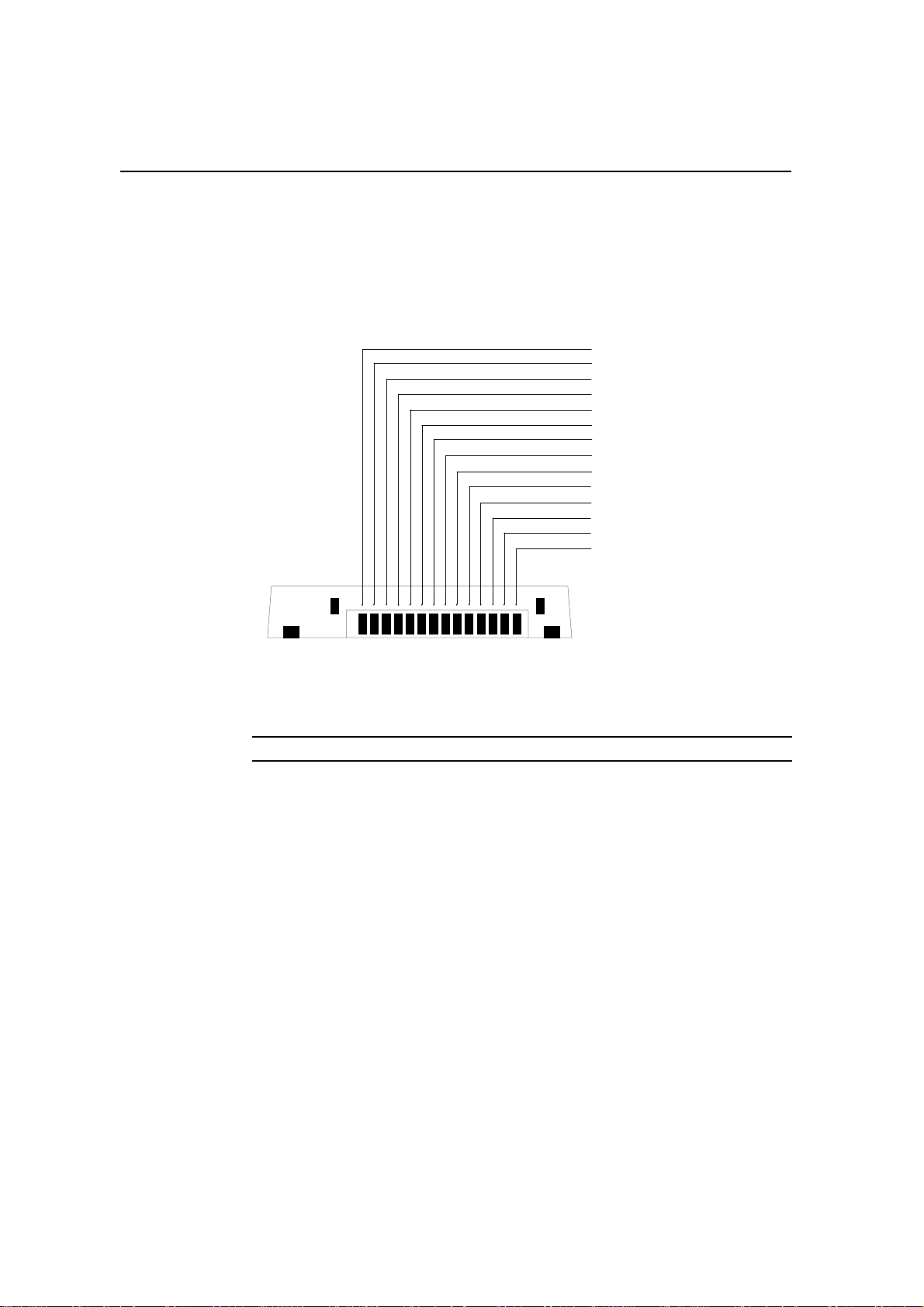
3. The built-in Test Program will give you access to the function or signal you
want to investigate, and any signal data you may need is found in the section
Connectors and Signals. There you will also find illustrations showing the
distribution of signals on the respective connector pins.
The telephone is to be tested with the following settings if nothing else is ex-
plicitly stated:
DC power supplied either via battery connector 6.8 V, or system connector
6.8 V.
Channel 1 RX = 935.0125 MHz, TX = 890.0125 MHz
TX power Test program, option 2:8
AFC ON Test program, option 15:1
Audio switches ON Test program, option 20:3
MANCHESTER switch OFF Test program, option 23:0
SAT tone OFF Test program, option 22:3, 22:5
Handset switch OFF Test program, option 21:0.
The above settings are automatically executed when entering the test program.
Channel selection: Enter channel number followed by #
Tx Power on: If Power Reduction(test #76) is activated,
PL2 and PL3 are indicated on the LCD by a #.
For detailed information regarding the adjustments, refer to Appendix B; Test
Program.
SERVICE: Telephone
8

Sequence of Adjustments
Item 1 VCTCXO
Purpose: Checking and, if necessary, calibration of the reference frequency
generator for the synthesizers.
Input signal: -50 dBm RF signal of 935.0125 MHz at the antenna connector.
Test method: Radio test set in duplex mode, measured with a frequency
counter.
Test program settings: 1:1 Channel selection
2:2 TX ON at Power Level 2
15:0 AFC OFF
Measurement point: Transmitter frequency at antenna connector.
Value: 890.0125 MHz.
Tolerance: 2.2 kHz.
Procedure: If the transmitter frequency is not within 890.0103 - 890.0147
MHz use test option 18 and press M& 0to calibrate the VCTCXO automat-
ically. When the calibration is done the new stored value will be displayed.
Note: Prior to an automatic calibration, test #15 must be set to its default value
(1 = normal operation).
Alternatively, the calibration can be done manually with the same test option.
To enable calibration and echo initial value, press M& #. Use the ▲and ▼
buttons to change value and press M& S to store the new value.
SERVICE: Telephone
9

Item 2 RSSI and Frequency Compensation
Purpose: Calibration of the RSSI (level detector) and the maximum allowed
frequency compensation.
Input signal: Initially -115 dBm RF signal of 935.0125 MHz at the antenna
connector.
Test method: Radio test set in RX mode.
Test program settings: 1:1 Channel selection
15:1 AFC ON.
Measurement point: None.
Value: None
Tolerance: None.
Procedure: Enter test option 9 and press M& S, and the stored reference
value for the RSSI indication will be displayed. If an alarm signal is heard the
error of the received frequency is greater than 1 kHz and further calibration
cannot be done.
Increase the signal strength to -60 dBm and press M& S. Change the RF-in
signal to 935.0175 MHz (+5 kHz), wait 5 seconds, then press M& Sand the
stored max. allowed frequency compensation value will be displayed.
SERVICE: Telephone
10

Item 3 RF Output Power
Purpose: Check and, if necessary, adjustment of the RF output power levels.
Input signal: None.
Test method: Radio test set in TX mode, measured with a RF power meter.
Test program settings: 1:1 Channel selection
2:2-7 TX Power Level 2 down to 7.
Measurement point: Output power at the antenna connector.
Values: PL Output Power
2 26.5 dBm
3 22.5 dBm
4 18.5 dBm
5 14.5 dBm
6 10.5 dBm
7 6.5 dBm
Tolerance: +2/-4 dBm at all power levels.
Procedure: If the transmitter output power is not within the above stated lim-
its use test option 5 and press either 0,1 or 2to select power table. The dis-
play will show selected table, power level and current voltage value. Use the
▲and ▼buttons to adjust the output power. Press M& Sto store the value
or M &# to step to the next power level. When all power levels in table 0
have been adjusted, table 1 will automatically be selected, starting with power
level 2. Press CLR when adjustment is ready to return to menu 0, "Test Input".
SERVICE: Telephone
11

Item 4 Maximum Deviation.
Purpose: Check and, if necessary, adjustment of the maximum deviation
from the transmitter.
Input signal: 1 kHz tone with a level of 700 mVRMS at the ATMS input on
the service adapter.
Test method: Radio test set in TX mode, measured with a deviation meter.
Test program settings: 1:1 Channel selection
2:2 TX On at Power Level 2
27:0 Selected TX source is ATMS
Measurement point: At the antenna connector.
Value: 7.7 kHz.
Tolerance: 1 kHz.
Procedure: If the transmitter deviation is exceeding 9.5 kHz use test option
14 and press M& #. Use the ▲and ▼buttons to adjust the deviation. Press
M& Sto store the new value.
Item 5 Nominal Deviation.
Purpose: Check and, if necessary, adjustment of the maximum deviation
from the transmitter.
Input signal: 1 kHz tone with a level of 307 mVRMS at the ATMS input on
the service adapter.
Test method: Radio test set in TX mode, measured with a deviation meter.
Test program settings: 1:1 Channel selection
2:2 TX On at Power Level 2
27:0 Selected TX source is ATMS
Measurement point: At the antenna connector.
Value: 5.7 kHz.
Tolerance: 10 %
Procedure: If the transmitter deviation is not within 5.2 - 6.2 kHz use test op-
tion 27 and press M& #. Use the ▲and ▼buttons to adjust the deviation.
Press M& Sto store the new value.
Check harmonic distortion on the nominal deviation from the transmitter. Not
to exceed 5 %.
SERVICE: Telephone
12

Item 6 SAT Deviation.
Purpose: Check and, if necessary, adjustment of the deviation of the SAT (su-
pervisor audio tone) from the transmitter.
Input signal: None.
Test method: Radio test set in TX mode, measured with a deviation meter.
Test program settings: 1:1 Channel selection
2:2 TX On at Power Level 2
20:0 Audio paths muted
22:0 Generate 5970 Hz signal
22:1 Generate 6000 Hz signal
22:2 Generate 6030 Hz signal
22:4 SAT switch unmuted
Note: For cellular tests, use 15 kHz LP filter.
Measurement point: At the antenna connector.
Value: 1.7 kHz.
Tolerance: 10 %.
Procedure: If the transmitter deviation is not within 1.53 - 1.87 kHz use test
option 22 and press M& #. Use the ▲and ▼ buttons to adjust the deviation.
Press M& Sto store the new value.
SERVICE: Telephone
13

Item 7 Wideband Data Deviation
Purpose: Check and, if necessary, adjustment of the deviation of the wide-
band data and ST (signalling tone) from the transmitter.
Input signal: None.
Test method: Radio test set in TX mode, measured with a deviation meter.
Test program settings: 1:1 Channel selection
2:2 TX On at Power Level 2
20:0 Audio paths muted
23:1 Generate "one’s"
Measurement point: At the antenna connector.
Value: 6.4 kHz.
Tolerance: 10 %.
Procedure: If the transmitter deviation is not within 5.8 - 7.0 kHz use test op-
tion 23 and press M& #. Use the ▲and ▼buttons to adjust the deviation.
Press M& Sto store the new value.
SERVICE: Telephone
14

Item 8 Audio From Mobile Station (AFMS)
Purpose: Check and, if necessary, adjustment of the deviation of the wide-
band data and ST (signalling tone) from the transmitter.
Input signal: -50 dBm RF signal of 935.0125 MHz at the antenna connector
with 1 kHz tone and 5.7 kHz deviation.
Test method: Radio test set in RX mode, measured with an AC voltmeter.
Test program settings: 1:1 Channel selection
2:2 TX On at Power Level 2
20:3 Both audio paths open
23:0 If set to 1 after Item 7
25:3 Volume level 3
Measurement point: At the AFMS output on the service adapter.
Value: 297 mVRMS.
Tolerance: 40 mV.
Procedure: If the audio signal from mobile station is not within 267 - 347
mVRMS use test option 10 and press M& #. Use the ▲and ▼ buttons to ad-
just the level. Press M& Sto store the new value.
Check the harmonic distortion on the AFMS signal. Not to exceed 5%.
Check that the receiver sensitivity is 20 dB SINAD(P) with an RF signal of
-113 dBm.
Item 9 Current
Purpose: To calibrate the current consumption of the telephone.
Input signal: 6.0 VDC via the system connector.
Test method: Measured with a DC-current meter.
Test program: 12 Current calibration.
Measurement point: At the current terminals of the Service Adapter.
Value: Shown by ammeter.
Tolerance: None.
Procedure: After entering test option 12 the current consumption in stand-by
is read from the ammeter. The value is divided by c. 23.33, entered from the
keypad to the telephone and stored with the buttons M& S. The telephone
will start to transmit on the lowest power level and the same procedure is re-
peated for all power levels.
SERVICE: Telephone
15

SERVICE: Telephone
16
Table of contents
Other Ericsson Cordless Telephone manuals

Ericsson
Ericsson DT400 User manual

Ericsson
Ericsson DT412 User manual

Ericsson
Ericsson DT590 User manual

Ericsson
Ericsson DT412 User manual

Ericsson
Ericsson DT292 User manual

Ericsson
Ericsson MASTR IIe User manual

Ericsson
Ericsson DT4 Series User manual

Ericsson
Ericsson DT288 User manual

Ericsson
Ericsson DT412 User manual

Ericsson
Ericsson 230 User manual

Ericsson
Ericsson DT292 User manual

Ericsson
Ericsson BS120 User manual

Ericsson
Ericsson DT570 User manual

Ericsson
Ericsson DT288 User manual

Ericsson
Ericsson 230i User manual

Ericsson
Ericsson DT368 User manual

Ericsson
Ericsson DT368 User manual

Ericsson
Ericsson DT292 User manual

Ericsson
Ericsson DR400 User manual

Ericsson
Ericsson DT690 User manual