Figures
Figure 1: Nd: YAG Laser Resonator Cavity.............................................................................. 5
Figure 2: Troubleshooting Sequence ..................................................................................... 7
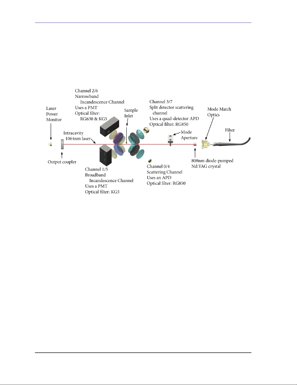
Figure 3: SP2 Spectrometer Head........................................................................................... 8
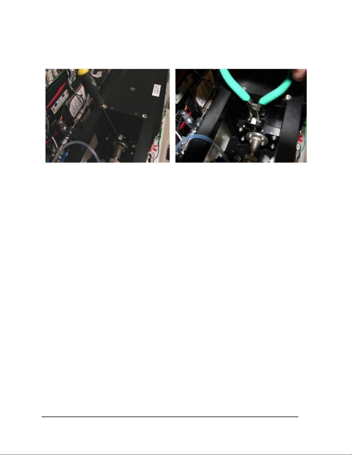
Figure 4: Mode Aperture Removal ....................................................................................... 10
Figure 5: Installing Mode Aperture in Upside-Down Position................................................ 11
Figure 6: Satisfactory Beam Profile ...................................................................................... 12
Figure 7: Undesired Higher Mode........................................................................................ 12
Figure 8: Coupler Chamber Sealing Screws .......................................................................... 13
Figure 9: Tip/tilt adjustment of output coupler mount ......................................................... 13
Figure 10: Angled entry of drivers in older systems ............................................................. 13
Figure 11: Attachment of Mode Aperture Alignment Tool ................................................... 15
Figure 12: Manual mode aperture alignment ...................................................................... 15
Figure 13: Application of extra force to assist stage springs ................................................. 16
Figure 14: Histogram Response as Chamber Plate is Translated........................................... 17
Figure 15: Ultra-Torr Fiber Passthrough Fitting.................................................................... 20
Figure 16: Unscrewing SMA Connector................................................................................ 21
Figure 17: Components of Fiber Passthrough ...................................................................... 21
Figure 18: Assembled SP2 Alignment Fixture....................................................................... 22
Figure 19: Frame-to-fixture fasteners.................................................................................. 22
Figure 20: Removing Output Coupler Mounting Screws....................................................... 23
Figure 21: Wiping the output coupler.................................................................................. 24
Figure 22: YAG Crystal and Optical Pump Assembly............................................................. 25
Figure 23: Fasteners securing YAG crystal holder to pump base........................................... 26
Figure 24: Three fasteners secure TMA to YAG crystal holder .............................................. 27
Figure 25: Screws securing halves of YAG Crystal Holder together ....................................... 27
Figure 26: YAG Crystal cushioned in holder ......................................................................... 28
Figure 27: Alignment Beam Centered on Pinholes ............................................................... 30
Figure 28: Paper between Crystal and Mode Match Optics.................................................. 31
Figure 29: Adjusters that aim the YAG Crystal Assembly...................................................... 31
Figure 30: Beam and Reflection Coincidence ....................................................................... 32
Figure 31: Paper Placed to Block Reflection from Crystal Face ............................................. 33
Figure 32: Light Concentric Around Entrance to Coupler Chamber........................................ 34
Figure 33: Locking and Adjustment Screws........................................................................... 35
Figure 34: Centered chamber (coplanar slide plate and slide rail end faces)......................... 36
Figure 35: SP2 Pump Laser in Protective Box ........................................................................ 37
Figure 36: Shorting Plug Detached (left) and Attached (right) to Power Connector ............... 38
Figure 37: Protective Cap SMA Fiber Connector; Cap Attached to Connector........................ 38