ERL L-PRO 4000 User manual

L-PRO 4000
Transmission Line Protection Relay
User Manual
Version 2.3 Rev 0


D02706R02.20 L-PRO 4000 User Manual i
Preface
Information in this document is subject to change without notice.
© 2013 ERLPhase Power Technologies Ltd. All rights reserved.
Reproduction in any manner whatsoever without the written permission of
ERLPhase Power Technologies Ltd. is strictly forbidden.
This manual is part of a complete set of product documentation that includes
detailed drawings and operation. Users should evaluate the information in the
context of the complete set of product documentation and their particular
applications. ERLPhase assumes no liability for any incidental, indirect or
consequential damages arising from the use of this documentation.
While all information presented is believed to be reliable and in accordance
with accepted engineering practices, ERLPhase makes no warranties as to the
completeness of the information.
All trademarks used in association with B-PRO, F-PRO, L-PRO, ProLogic,
T-PRO, TESLA, TESLA Control Panel, Relay Control Panel, RecordGraph
and RecordBase are trademarks of ERLPhase Power Technologies Ltd.
Windows®is a registered trademark of the Microsoft Corporation.
Procomm®is a registered trademark of Symantec.
HyperTerminal®is a registered trademark of Hilgraeve.
Modbus®is a registered trademark of Modicon.
Contact Information
ERLPhase Power Technologies Ltd.
Website: www.erlphase.com
Email: [email protected]
Technical Support
Email: [email protected]
Tel: 1-204-477-0591


D02706R02.30 L-PRO 4000 User Manual iii
Table of Contents
Preface ......................................................................................i
Contact Information ...................................................................i
Table of Contents .................................................................... iii
Using This Guide .................................................................... vii
Acronyms.................................................................................ix
Version Compatibility ...............................................................xi
PC System Requirements and Software Installation ............. xiii
1 Overview ................................................................. 1-1
Introduction ...................................................................... 1-1
Front View........................................................................ 1-3
Rear View ........................................................................ 1-4
Model Options/Ordering................................................... 1-6
2 Setup and Communications.................................. 2-1
Introduction ...................................................................... 2-1
Power Supply................................................................... 2-1
IRIG-B Time Input ............................................................ 2-1
Communicating with the Relay Intelligent Electronic
Device (IED)..................................................................... 2-2
USB Link .......................................................................... 2-3
Network Link .................................................................... 2-5
Direct Serial Link.............................................................. 2-6
Modem Link ..................................................................... 2-7
Using HyperTerminal to Access the Relay’s Maintenance
Menu ................................................................................ 2-9
Firmware Update ........................................................... 2-12
Setting the Baud Rate.................................................... 2-13
Accessing the Relay’s SCADA Services........................ 2-14
Communication Port Details .......................................... 2-15
3 Using the IED (Getting Started) ............................ 3-1
Introduction ...................................................................... 3-1
Start-up Sequence ........................................................... 3-1
Interfacing with the Relay................................................. 3-1
Front Panel Display.......................................................... 3-2
Terminal Mode ................................................................. 3-7
Relay Control Panel ......................................................... 3-7
4 Protection Functions and Specifications ............ 4-1

Table of Contents
iv L-PRO 4000 User Manual D02706R02.30
Protection and Recording Functions................................ 4-2
Communication-Aided Scheme ..................................... 4-47
Recording Functions ...................................................... 4-51
Event Log....................................................................... 4-54
Fault Log ........................................................................ 4-55
5 Data Communications ........................................... 5-1
Introduction ...................................................................... 5-1
SCADA Protocol .............................................................. 5-1
IEC 61850 Communication .............................................. 5-7
6 Offliner Settings Software ..................................... 6-1
Introduction ...................................................................... 6-1
Offliner Features .............................................................. 6-2
Offliner Keyboard Shortcuts............................................. 6-5
Handling Backward Compatibility .................................... 6-6
RecordBase View Software ............................................. 6-8
Main Branches from the Tree View.................................. 6-9
Settings From a Record ................................................. 6-29
7 Acceptance/Protection Function Test Guide ...... 7-1
Introduction ...................................................................... 7-1
Acceptance Testing ......................................................... 7-1
L-PRO Acceptance Test Procedure Outline .................... 7-4
8 Installation .............................................................. 8-1
Introduction ...................................................................... 8-1
Physical Mounting............................................................ 8-1
AC and DC Wiring............................................................ 8-1
Communication Wiring..................................................... 8-1
Appendix A IED Specifications..................................... A-1
Distance Element Operating Time Curves at Nominal
Frequency ........................................................................A-7
Frequency Element Operating Time Curves....................A-9
External Input Pickup Filter ............................................A-11
Appendix B IED Settings and Ranges ......................... B-1
Settings and Ranges........................................................B-1
Appendix C Hardware Description ...............................C-1
Appendix D Event Messages .......................................D-1
Appendix E Modbus RTU Communication Protocol .... E-1
Appendix F DNP3 Device Profile ................................. F-1
Appendix G Mechanical Drawings ...............................G-1

Table of Contents
D02706R02.30 L-PRO 4000 User Manual v
Appendix H Rear Panel Drawings................................H-1
Appendix I AC Schematic Drawings ............................. I-1
Appendix J DC Schematic Drawings ............................J-1
Appendix K Function Logic Diagram............................ K-1
Appendix L L-PRO Setting Example ............................ L-1
Switching Setting Groups................................................. L-2
79 Auto-recloser Examples.............................................. L-9
Appendix M Failure Modes ......................................... M-1
Actions ............................................................................ M-1
Appendix N IEC61850 Implementation ........................N-1
Protocol Implementation Conformance Statement
(PICS) ..............................................................................N-1
Model Implementation Conformance Statement
(MICS)..............................................................................N-8
Data Mapping Specifications .........................................N-40
Index ......................................................................................... I


D02706R02.30 L-PRO 4000 User Manual vii
Using This Guide
This User Manual describes the installation and operation of the L-PRO line
protection relay. It is intended to support the first time user and clarify the de-
tails of the equipment.
The manual uses a number of conventions to denote special information:
Example Describes
Start>Settings>Control Panel Choose the Control Panel submenu in the Set-
tings submenu on the Start menu.
Right-click Click the right mouse button.
Recordings Menu items and tabs are shown in italics.
Service User input or keystrokes are shown in bold.
Text boxes similar to this one Relate important notes and information.
.. Indicates more screens.
Indicates further drop-down menu, click to dis-
play list.
Indicates a warning.


D02706R02.30 L-PRO 4000 User Manual ix
Acronyms
ASG - Active Setting Group
CCVT - Capacitance Coupled Voltage Transformer
CID - file extension (.CID) for Configured IED Description
CS - Control Switch
CT - Current Transformer
DCB - Directional Comparison Blocking
DCE - Data Communication Equipment
DIB - Digital Input Board
DIGIO - Digital Input/Output Board
DMDA - Dead Main Dead Aux
DMLA - Dead Main Live Aux
DSP - Digital signal processor
DTE - Data Terminal Equipment
GFPCB - Graphics Front Panel Comm Board
GFPDB - Graphics Front Panel Display Board
GPS - Global Positioning System
HMI - Human Machine Interface
ICD - file extension (.ICD) for IED Capability Description
IEC - International Electrotechnical Commission
IED - Intelligent Electronic Device
IP - Internet Protocol (IP) address
IRIG-B - Inter-range instrumentation group time codes
LE- Load Encroachment
LED - Light-emitting Diode
LHS - Left Hand Side
LMDA - Live Main Dead Aux

Acronyms
x L-PRO 4000 User Manual D02706R02.30
LOCB - L-PRO Output Contact Board
LOP - Loss of Potential
MPB - Main Processor Board
MPC - Micro Processor
PLC - Programmable Logic Controller
POTT - Permissive Over-reaching Transfer Trip
PUTT - Permissive Under-reaching Transfer Trip
PT - Permissive Trip
RAIB -Relay AC Analog Input Board
RASB -Relay AC Analog Sensor Boards
RHS - Right Hand Side
RPCB - Rear Panel Comm Board
RTOS - Real Time Operating System
RTU - Remote Terminal Unit
SCADA - Supervisory Control And Data Acquisition
SG - Setting Group
SIR ratio - Source Impedance Ratio
SOTF - Switch On To Fault
TT - Transfer Trip
TUI - Terminal User Interface
UI - User Interface
VI - Virtual Input
WI - Weak Infeed
D02706R02.30 L-PRO 4000 User Manual xi
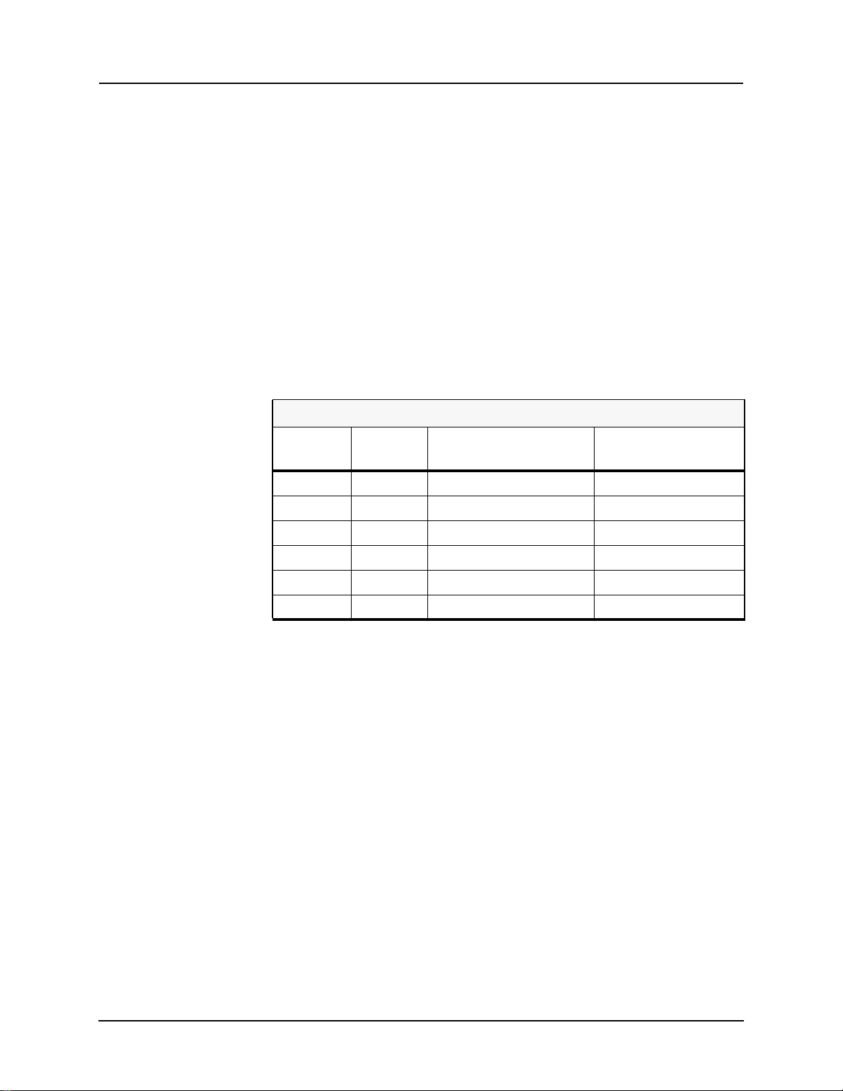
Version Compatibility
This chart indicates the versions of Offliner Settings, RecordBase View and
the User Manual which are compatible with different versions of L-PRO firm-
ware.
RecordBase View and Offliner Settings are backward compatible with all ear-
lier versions of records and setting files. Use RecordBase View to view records
produced by any version of L-PRO firmware and Offliner Settings can create
and edit older setting file versions.
Minor releases (designated with a letter suffix - e.g. v3.1a) maintain the same
compatibility as their base version. For example. L-PRO firmware v3.1c and
Offliner Settings v3.1a are compatible.
Please contact ERLPhase Customer Service for complete Revision History.
L-PRO 4000 Firmware/Software Compatibility Guide
L-PRO
Firmware
Setting
Version Compatible Offliner Settings ICD File Version
v2.3 404 v2.3 or greater 2.0
v2.2 404 v2.3 or greater 2.0
v2.1a 403 v2.1 or greater 0.0
v2.1 403 v2.1 or greater n/a
v2.0 402 v2.0 or greater n/a
v1.0 401 v1.0 or greater n/a


D02706R02.30 L-PRO 4000 User Manual xiii
PC System Requirements and Software
Installation
Hardware
The minimum hardware requirements are:
• 1 GHz processor
• 2 GB RAM
• 20 GB available hard disk space
• USB port
• Serial communication port
Operating System
The following software must be installed and functional prior to installing the
applications:
• Microsoft Windows XP Professional Service Pack 3 or
• Microsoft Windows 7 Professional Service Pack 1 32-bit or 64-bit
Relay Control Panel requires Windows XP SP3 (it will not work on earlier ver-
sions of Windows).
Software Installation
The CD-ROM contains software and the User Manual for the L-PRO Trans-
mission Line Protection Relay.
Software is installed directly from the CD-ROM to a Windows PC. Alterna-
tively, create installation diskettes to install software on computers without a
CD-ROM drive.
The CD-ROM contains the following:
• L-PRO Offliner Settings: Offliner settings program for the relay
• L-PRO Firmware: Firmware and installation instructions
• L-PRO User Manual: L-PRO manual in PDF format
• L-PRO Function Logic Diagram: diagram in PDF format
• Relay Control Panel: software
• Relay Control Panel User Manual: manual in PDF format
• USB Driver
To Install Software on the Computer
Insert the CD-ROM in the drive. The CD-ROM should open automatically. If
the CD-ROM does not open automatically, go to Windows Explorer and find
the CD-ROM (usually on D drive). Open the ERLPhase.exe file to launch the
CD-ROM.

PC System Requirements and Software Installation
xiv L-PRO 4000 User Manual D02706R02.30
To install the software on the computer, click the desired item on the screen.
The installation program launches automatically. Installation may take a few
minutes to start.
To view the L-PRO User Manual the user must have Adobe Acrobat on the
computer. If a copy is needed, download a copy at www.adobe.com.
Anti-virus/Anti-spyware Software
If an anti-virus/anti-spyware software on your local system identifies any of
the ERLPhase applications as a “potential threat”, it will be necessary to con-
figure your anti-virus/anti-software to classify it as “safe” for its proper oper-
ation. Please consult the appropriate anti-virus/anti-spyware software
documentation to determine the relevant procedure.

D02706R02.30 L-PRO 4000 User Manual 1-1
1 Overview
1.1 Introduction
The L-PRO 4000 provides easy-to-use, state-of-the-art comprehensive dis-
tance and directional line protection for medium to extra-highvoltage transmis-
sion lines using communication-based schemes. It provides control,
automation, metering, monitoring, fault oscillography, dynamic swing record-
ing, event logging with advanced communications in a flexible cost effective
package.
The primary protection is line protection with 5 zones of phase and ground dis-
tance functions – user-defined Mho or Quadrilateral shapes and communica-
tions based schemes (i.e. teleprotection or pilot schemes).
To provide a complete package of protection and control the relay supplies oth-
er functions such as:
• 1.0 to 1.3 cycle operation at 80% reach, ideal for EHV transmission line
applications
• Ring bus capability – breaker failure and individual breaker monitoring
• 4-shot recloser with dead line/dead bus control and sync check
• Single pole and three pole trip and reclose
• 24 statements of ProLogic addresses special protection needs
• Power Swing Blocking / Tripping
• Load Encroachment
• Switch On To Fault function
• VT Supervision function
• CT Supervision function
• Over / Under Voltage functions
• 8 Setting Groups (SG) with setting group logic
• Back up Directional overcurrent and earth fault protection
• Over / Under / Rate of change of frequency devices
Relay Control Panel (RCP) is the Windows graphical user interface software
tool provided with all 3000, 4000 series and higher (new generation) ERL re-
lays to communicate, retrieve and manage records, event logs, fault logs, man-
age settings (identification, protection, SCADA etc.,), display real time
metering values, view, analyze, and export records in COMTRADE format.
In addition to the protection functions the relay provides fault recording (96
samples/cycle) to analyze faults and to review the operation of the overall pro-
tection scheme. The relay also has low speed swing recording which can be
used to analyze system stability. The triggers for fault recording are established
1 Overview
1-2 L-PRO 4000 User Manual D02706R02.30
by programming the output matrix and allowing any internal relay function or
any external input or any GOOSE messaging input to initiate recording.
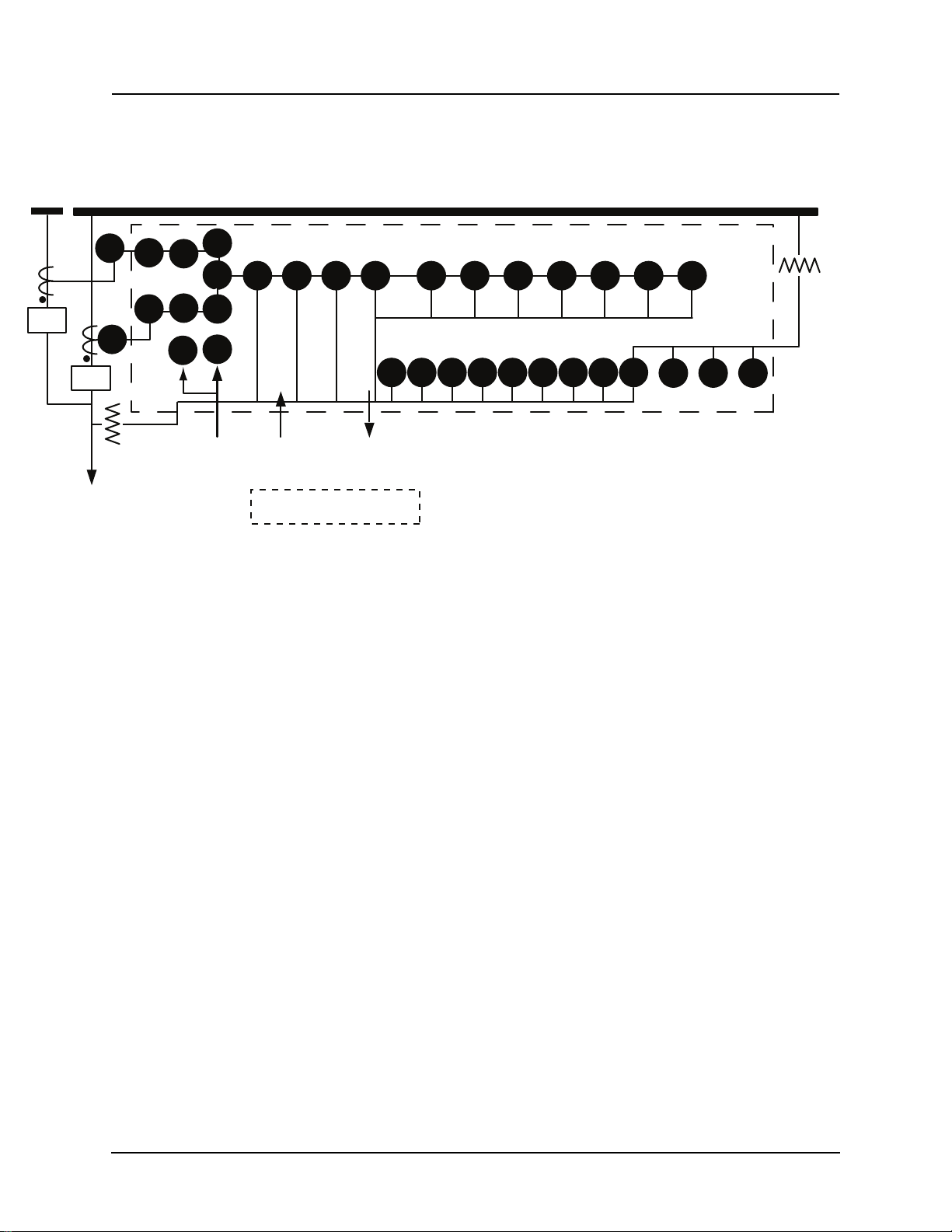
Figure 1.1: L-PRO Relay Function Line Diagram
50LS: Low set overcurrent
PL: ProLogic
WI: Weak infeed
5050N
/67
27 59 60 WI Rec. 25/27
/59
21P 21N 68 50/67 51/67 50N/
67
51N/
67
46/50
/67 Rec.
46/51
/67
Bus 1
52-2
PT
PT
CT
Line
5 Zones 5 Zones Dead
Line
Pickup
Fault Recording
6 Voltages
12 Currents
Protection Elements
External Inputs
Active Setting Group
Output Contacts
Swing Recording
Positive Sequence Voltage
Positive Sequence Current
System Frequency
Real Power
Reactive Power
6 Analog
Current
Inputs
14 Output Contacts
1 Relay Inoperative
Alarm Contact
7 Output Contacts
59 27
52-1
50
BF
50
BF
Σ
CT
Rec.
Rec.
Bus 2
9 External
Inputs
11 External
Inputs
Rec.
Rec.
79-1,3
79-1,3
81
50
LS
50
LS PL
Optional I/O
59N 60
CTS

1 Overview
D02706R02.30 L-PRO 4000 User Manual 1-3
1.2 Front View
Figure 1.2: L-PRO Relay Front View (3U)
Figure 1.3: L-PRO Relay Front View (4U)
RELAY FUNCTIONAL
IRIG-B FUNCTIONAL
SERVICE REQUIRED
TEST MODE
ALARM
LINE PROTECTION RELAY
L-PRO
X
100BASE-T
(119) (150)
USB
12
3
456
1. Front display of time, alarms and relay target
2. LEDs indicating status of relay
3. USB Port 150 for maintenance interface
4. Push buttons to manipulate information on settings, display and to clear targets
5. 11 Target Programmable LEDs
6. Ethernet Port 119
RELAY FUNCTIONAL
IRIG-B FUNCTIONAL
SERVICE REQUIRED
TEST MODE
ALARM
LINE PROTECTION RELAY
L-PRO
X
100BASE-T
(119) (150)
USB
12
3
45 6
1. Front display of time, alarms and relay target
2. LEDs indicating status of relay
3. USB Port 150 for maintenance interface
4. Push buttons to manipulate information on settings, display and to clear targets
5. 11 Target Programmable LEDs
6. Ethernet Port 119

1 Overview
1-4 L-PRO 4000 User Manual D02706R02.30
1.3 Rear View
Figure 1.4: L-PRO Relay Rear View (3U)
Power Supply
±10%
48 to 250 Vdc
100 to 240 Vac
I1A I2A I3A I4A
I1B I2B I3B I4B
I1C I2C I3C I4C
Input
1A 50Hz5A 60Hz
Main AC Line Currents
Made in Canada
AC Current Inputs (Record Only)
Aux. AC Line Currents
300 312 32 4
301 31 3 325302 31 4 326303 31 5 327304 31 6 328305 31 7 329306 31 8 330307 31 9 331308 320 332309 321 33 3310 322 334
336
311 323 335
337
VA VAVB VBVC VCNN
Aux. AC Volts Main AC Volts
Unused Unused
Unused
200 21 8201 219202 220203 221204 222205 223206 224207 225208 226209 227210 228
211 229
212 230213 231214 232215 233216 234217 235
RELAY
INOPERATIVE
NCNO
NCNO NCNO NO NO
NO
NO NO NO NO NO NO NO NO NO
Output
Contacts
Output
Contacts
678
123910 11 12 13 14
45
123456789
External
Inputs
100 10 1 102 103 104 105 106 107 108 109 110 111 112 113 114 115 11 6 117
48 125 250 V48 125 250 V48 125 250 V48 125 250 V48 125 250 V48 125 250 V48 125 250 V48 125 250 V48 125 250 V
Modem IRIG-B SCADA COM
100BASE-
1000BASE-
FXT
LXTX
100BASE-
1000BASE-
FXT
LXTX
RXRX TXTX
11 8 11 9 120
121
122 123
7. Ports 100-117: 9 External Programmable Inputs
8. Ports 200-201: Relay inoperative contact
Ports 202-229: 14 programmable output contacts
Ports 230-235: Unused
9. Port 118: Internal modem
10.Port 119-120: 100BASE-T or 100BASE-FX Ethernet Ports
11.Port 121: External clock, IRIG-B modulated or unmodulated
12.Port 122: SCADA
13.Port 123: Direct/Modem RS-232 Port
14.Ports 324-327, 330-333: AC voltage inputs
15.Ports 300-323: AC current inputs
16.Ports 230-235, 328, 329, 334, 335: Unused
17.Ports 336-337: Power supply
18.Port with GND symbol: Chassis Ground
913
10 11 12
14 17
16
14 18
8
15
7
8
Table of contents
Other ERL Relay manuals


