ERL F-PRO 5100 User manual

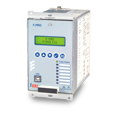
F-PRO
Feeder Protection Relay
Model 5100
User Manual
Version 4.0 Rev 0


D02416R04.00 F-PRO 5100 User Manual i
Preface
Information in this document is subject to change without notice.
© 2016 ERLPhase Power Technologies Ltd. All rights reserved.
Reproduction in any manner whatsoever without the written permission of
ERLPhase Power Technologies Ltd. is strictly forbidden.
This manual is part of a complete set of product documentation that includes
detailed drawings and operation. Users should evaluate the information in the
context of the complete set of product documentation and their particular
applications. ERLPhase assumes no liability for any incidental, indirect or
consequential damages arising from the use of this documentation.
While all information presented is believed to be reliable and in accordance
with accepted engineering practices, ERLPhase makes no warranties as to the
completeness of the information.
All trademarks used in association with B-PRO, F-PRO, iTMU, L-PRO,
ProLogic, S-PRO, T-PRO, TESLA, TESLA Control Panel, Relay Control
Panel, RecordGraph and RecordBase are trademarks of ERLPhase Power
Technologies Ltd.
Windows®is a registered trademark of the Microsoft Corporation.
HyperTerminal®is a registered trademark of Hilgraeve.
Modbus®is a registered trademark of Modicon.
Contact Information
ERLPhase Power Technologies Ltd
Website: www.erlphase.com
Email: [email protected]
Technical Support
Email: [email protected]
Tel: 1-204-477-0591


D02416R04.00 F-PRO 5100 User Manual iii
Table of Contents
Preface ......................................................................................i
Contact Information ...................................................................i
Table of Contents .................................................................... iii
Using This Guide ......................................................................v
Version Compatibility.............................................................. vii
1 Overview ................................................................. 1-1
Front View........................................................................ 1-3
Back View ........................................................................ 1-3
Model Options/Ordering................................................... 1-4
2 Setup and Communications.................................. 2-1
Power Supply................................................................... 2-1
IRIG-B Time Input ............................................................ 2-1
Communicating with the Relay (IED) ............................... 2-2
Using HyperTerminal to Access the Relay’s User
Interface ........................................................................... 2-5
Setting the Baud Rate...................................................... 2-7
Accessing the Relay’s SCADA Services.......................... 2-8
Communication Port Details ............................................ 2-9
Maintenance Menu ........................................................ 2-12
Firmware Update ........................................................... 2-13
3 Using the IED (Getting Started) ............................ 3-1
Start-up Sequence ........................................................... 3-1
Front Panel Display.......................................................... 3-2
Terminal Mode ................................................................. 3-5
View, Change or Service Login........................................ 3-9
Breaker Login................................................................. 3-13
Metering Data ................................................................ 3-14
4 Protection Functions and Specifications ............ 4-1
Protection and Recording Functions................................ 4-1
Demand Metering .......................................................... 4-17
Accumulated Energy (kWh, kVARh metering)............... 4-20
Recording Functions ...................................................... 4-26
Logging Functions.......................................................... 4-28
5 Offliner Settings Software..................................... 5-1
Introduction ...................................................................... 5-1
Installing PC Software...................................................... 5-2

Table of Contents
iv F-PRO 5100 User Manual D02416R04.00
Offliner Features .............................................................. 5-2
Handling Backward Compatibility .................................... 5-4
RecordBase View Software ............................................. 5-5
Main Branches from the Tree View.................................. 5-6
Settings From a Record ................................................. 5-19
6 Testing the F-PRO Functions................................ 6-1
7 Installation .............................................................. 7-1
Physical Mounting............................................................ 7-1
AC and DC Wiring............................................................ 7-1
Communication Wiring..................................................... 7-1
Appendix A IED Specifications .............................................A-1
Distance Element Operating Time Curves at Nominal
Frequency ........................................................................A-4
Frequency Element Operating Time Curves....................A-5
Appendix B IED Settings and Ranges..................................B-1
Appendix C Hardware Description .......................................C-1
Appendix D Event Messages ...............................................D-1
Appendix E Modbus RTU Communication Protocol.............E-1
Appendix F DNP3 Communication Protocol......................... F-1
Appendix G Mechanical Drawings........................................G-1
Appendix H Rear Panel Drawings ........................................H-1
Appendix I AC Schematic Drawing........................................ I-1
Appendix J DC Schematic Drawing.......................................J-1
Appendix K Function Logic Diagram ....................................K-1
Appendix L F-PRO Setting Example .................................... L-1
Setting Examples ............................................................. L-2
Switching Setting Groups................................................. L-5
Index..........................................................................................I

D02416R04.00 F-PRO 5100 User Manual v
Using This Guide
This User Manual describes the installation and operation of the F-PRO feeder
protection relay. It is intended to support the first time user and clarify the de-
tails of the equipment.
The manual uses a number of conventions to denote special information:
Example Describes
Start>Settings>Control Panel Choose the Control Panel submenu in the Set-
tings submenu on the Start menu.
Right-click Click the right mouse button.
Recordings Menu items and tabs are shown in italics.
service User input or keystrokes are shown in bold.
Text boxes similar to this one Relate important notes and information.
.. Indicates more screens.
Indicates further drop-down menu, click to dis-
play list.
Indicates a warning.


D02416R04.00 F-PRO 5100 User Manual vii
Version Compatibility
This chart indicates the versions of Offliner Settings, RecordBase View and
the User Manual which are compatible with different versions of F-PRO firm-
ware.
RecordBase View and Offliner Settings are backward compatible with all ear-
lier versions of records and setting files. You can use RecordBase View to view
records produced by any version of F-PRO firmware and Offliner Settings can
create and edit older setting file versions.
Minor releases (designated with a letter suffix - e.g. v3.1a) maintain the same
compatibility as their base version. For example. F-PRO firmware v3.1c and
Offliner Settings v3.1a are compatible.
F-PRO Firmware/Software Compatibility Guide
F-PRO
Firmware
Setting File
Version Compatible Offliner Settings
v4.0 24000 v1.0 or greater
v3.0 24000 v1.0 and greater
v3.0 2v3.0 or greater
v2.0a 2v2.0 or greater
v2.0 2v2.0 or greater
v1.0d 1v1.0b or greater
v1.0c 1v1.0a or greater
v1.0b 1v1.0a or greater
v1.0a 1v1.0a or greater
v1.0 1v1.0 or greater
Please contact ERLPhase Customer Service for complete Revision History.


D02416R04.00 F-PRO 5100 User Manual 1-1
1 Overview
The F-PRO (model 5100) is a microprocessor-based relay providing compre-
hensive directional overcurrent protection, reclosing, metering, breaker moni-
toring and recording functions suitable for medium and low voltage lines.
F-PRO has two working modes—online and offline. In the online mode you
can use any communication software package (e.g. Procomm or HyperTermi-
nal) to connect to the F-PRO using VT100 terminal emulation. In online mode
you can:
• change and review relay settings
• view event and metering information
• initiate and retrieve recordings, and retrieve settings
In offline mode you can use Offliner Settings and RecordBase View software
to:
• create and review relay settings
• analyze fault waveforms
• store records
F-PRO Feeder Protection Relay
Offline Mode - Settings Software
Online Mode - Terminal Mode
F-PRO
Feeder Protection
Model 5100
Port 1
Date &
Time
View
Readings
View
Logs
Prev Next
Target
Clear
Target
1999 JUN 07
Relay Functional
IRIG-B Functional
Service Required
Test Mode
Alarm
In addition to the protection functions F-PRO provides fault recording (96
sample/cycle) to facilitate analysis of the power system after a disturbance has
taken place. The triggers for fault recording are established by programming
the output matrix and allowing any internal relay function or any external input
to initiate recording.
The primary protection provided is overcurrent based. A library for these
overcurrent functions provides commonly used IEEE and IEC inverse curves.
Because the curves are equation-driven, you can choose to enter an equation
parameter directly, creating other overcurrent shapes as needed. All
overcurrent functions are provided with directional control, if required, using
the ERLPhase method of positive sequence control.

1 Overview
1-2 F-PRO 5100 User Manual D02416R04.00
To provide a complete package of protection and control, F-PRO provides oth-
er functions such as:
• ring bus capability to protect and monitor lines connected to ring schemes
Current inputs are labelled Main and Aux inputs to denote the breaker ring
current inputs. Use F-PRO with straight single breaker line schemes by us-
ing the main current inputs
• breaker failure detection and monitoring
• 2 completely dedicated four shot reclosers devices 79 Main and 79 Aux to
control line reclosing needs along with device 25C Sync Check/Dead Bus/
Dead Line supervision
• low set overcurrent functions for each breaker as well as for the summated
line currents that include phase, neutral and negative sequence functions
• Watt, VAR flow detectors as well as undervoltage, overvoltage and over/
under frequency functions (Freq ROC) to provide protection for issues
such as inter-tie protection needs
• ProLogic provide a flexible way to address special protection needs. Ten
ProLogic statements are provided
• Breaker Logic, Group Logic, Demand Metering
Analog Inputs
4 Analog Voltages
1 Three-phase Input
1 Single-phase Input
6 Analog Currents
2 Three-phase Inputs
Outputs
12 Output Contacts
1 Relay Inoperative
Alarm Contact
Inputs
9 External Inputs
Metering (Front Display)
Primary Pos. Sequence Volts, Amps,
Primary Watts and VARs
Frequency
THD (Total Harmonic Distortion)
PF (Power Factor)
Primary Phase Voltage, Current, Phase
Angle (A, B, C)
Peak Demand MW, MVAR In and
Out Phase Currents
Energy Values MWh In and Out
MVARh In and Out
3I0
59-1 59-2 27-1 27-2 60 81-1 81-2 81-3 81-4 Rec
79
Main
32P 32Q
50LS-2
50LS-1 50BF
25C
Protected
Feeder
Feeder
Feeder
CT 1
CT 2
PT (1 ph)
PT (3 ph)
Feeder
Source Rec
THD
Σ
Rec
Rec
Metering
21P
46/
50/51/
67
50N/51N
67
50/51/
67
50LS-2 50BF
79Aux
50LS-1
Ring Bus
Trend Recording (Primary)
Real Power (MW In and Out)
Reactive Power (MVAR In and Out)
3 Phase Voltages (Va, Vb, Vc)
3 Phase Currents (Ia, Ib, Ic)
Real Energy (MWh In and Out)
Reactive Energy (MVARh In and Out)
THD Level (%)
System Frequency
Fault Recording
4 Voltages
6 Currents
97 Unique Events
Aux.
Main
Figure 1.1: F-PRO Line Diagram

1 Overview
D02416R04.00 F-PRO 5100 User Manual 1-3
Front View
1. Front display of time, alarms, relay target and metering
2. Relay target LED (red)
3. LEDs indicating status of relay
4. Communications serial Port 1 for laptop computer
5. Clear target push button
6. Push buttons to manipulate information on LCD display
F-PRO
Feeder Protection Relay
Model 5100
Relay Functional
IRIG-B Functional
Service Required
Test Mode
Alarm
Port 1
NextView
Readings
View
Logs
Previous
456
Target
Clear
Target
2000 Jan 07 11:49:54
Date &
Time
1 2 3
Figure 1.2: F-PRO Front View
Back View
VA VB VC N
Main AC Line Currents Main AC Volts Power Supply
300 301 302 303 305 306 307 308 309 310 312311 313 314 315 316 317 318 319 320 321 322 323 324 326 327 328 329 330 331 332 333325
Case
Ground
231 232 233
Relay
Inoperative
Output Relay Contracts
200 201 202 203 204 205 206 207 208 209 210 212211 213 214 215 216 217 218 219 220 221 222 223 224 226 227 228 229 230225
External
Inputs
100 101 102 103 104 105 106 107 108 109 110 112111 113 114 115 116 117
+ - + - + - + - + - + - + - + - + -
234 235
Port 4
Unused
Port 3
SCADA
IRIG-B
1 2 34 56 987
Out 1 Out 2 Out 3 Out 4 Out 5 Out 6 Out 7 Out 8 Out 9 Out 10 Out 11 Out 12
I1 A I1 B I1 C I2 A I2 B I2 C I3 A I3 B I3 C I4 A I4 B
+ -
VA VB
I4 C VC
7. Port 5 - 10BaseT Ethernet Port/Internal Modem (optional)
8. External clock, IRIG-B modulated or unmodulated
9. Port 2 - Direct/Modem RS-232 Port
10. Port 3 - SCADA
11. Port 4 - unused
12. Case ground
13. 9 programmable external inputs (1 to 9)
14. This row contains 2 distinct areas from left to right:
12 programmable output relay contacts and relay inoperative contact
15. This row contains 3 distinct areas from left to right:
6 ac current inputs
4 ac voltage inputs
Power supply
13
14
15
Output
Contacts
In. Freq. Aux.AC Line Currents AC Currents Inputs
Nominal
48-250 Vdc
120 Vac
Aux. AC Volts
Unused
N
Sync AC
Volts
125Vdc125Vdc 125Vdc 125Vdc 125Vdc 125Vdc 125Vdc 125Vdc 125Vdc
Port 2
Direct/Modem
Port 5
VN
Unused
7 8 9 10 11 12
Figure 1.3: F-PRO Back View

1 Overview
1-4 F-PRO 5100 User Manual D02416R04.00
AC Current and
Voltage Inputs F-PRO is provided with terminal blocks for up to 6 ac currents and 4 phase-to-
neutral voltages.
Each of the current input circuits has polarity (•) marks.
A complete schematic of current and voltage circuits is shown, for details see
“AC Schematic Drawing” in Appendix I and “DC Schematic Drawing”
in Appendix J.
External Inputs The F-PRO relay contains 9 programmable external inputs. External dc voltage
of either 48/125 volts or 125/250 volts nominal are possible depending on the
range provided.
Output Relay
Contacts The F-PRO relay has 12 output relay contacts. Each contact is programmable
and has breaker tripping capability. All output contacts are isolated from each
other. The output contacts are closed for a minimum of 100 ms after operation.
Relay Inoperative
Alarm Output If the relay becomes inoperative, then the Relay Inoperative Alarm output con-
tact closes and all tripping functions are blocked.
Model Options/Ordering
F-PRO is available as a horizontal mount, for details see “Mechanical Draw-
ings” in Appendix G.
F-PRO is available with an internal modem card or internal network card.
The CT inputs are 1 A nominal or 5 A nominal. The external inputs are 48/125
Vdc or 125/250 Vdc. The system base frequency is either 50 Hz or 60 Hz.
All of the above options must be specified at the time of ordering.

D02416R04.00 F-PRO 5100 User Manual 2-1
2 Setup and Communications
Power Supply
A wide range power supply is standard. The nominal operating range is 48–250
Vdc, 120 Vac, 50/60 Hz. To protect against possible short circuit in the supply
use an inline fuse or circuit breaker with a 5 A rating. Make the chassis ground
connection to ensure proper operation and safety.
There are no power switches on the relay. When the power supply is connect-
ed, the relay starts its initialization process and takes about 40 seconds to com-
plete showing the green Relay Functional LED.
Case Grounding You must ground the relay to station ground using the case-grounding terminal
at the back of the relay, for details see for details see Figure 1.3: F-PRO Back
View on page 1-3.
WARNING!
To ensure safety and proper operation you must connect the relay to
the station ground using the rear grounding terminal on the relay.
Ground the relay even when testing.
Do not rely on the rack mounting screws to provide case grounding.
IRIG-B Time Input
The relay is equipped to handle modulated or unmodulated GPS satellite time
IRIG-B signals. The IRIG-B time signal is connected to the BNC connection
on the back of the relay. When the IRIG-B signal is provided to the relay and
is enabled in the settings through the user interface, the IRIG-B functional LED
comes on and the relay clock is referenced to this signal. No settings are re-
quired to differentiate between modulated or unmodulated signals; this is au-
tomatically detected by the relay.
You enable or disable the IEEE 1344 extension in the terminal mode settings
Utilities>Setup>Time, for details see “Utilities” on page 3-14. The enabled
mode allows the year to be received from the IRIG-B signal. If the available
IRIG-B signal has no year extension, this setting should be disabled.

2 Setup and Communications
2-2 F-PRO 5100 User Manual D02416R04.00
Communicating with the Relay (IED)
You can connect to the relay to access its user interface and SCADA services:
• direct serial link (user interface and SCADA)
• external or internal modem link (user interface only)
• ethernet network link (user interface and SCADA)
Direct Serial Link
F-PRO
Feeder Protection
Model 5100
Port 1
Date &
Time
View
Readings
View
Logs
Prev Next
Target
Clear
Target
1999 JUN 07
Relay Functional
IRIG-B Functional
Service Required
Test Mode
Alarm
Port 1
Laptop PC
Relay Port 1 or rear Port 2
to PC Serial Port
Serial Extension Cable
Port 2 - direct/modem
Figure 2.1: Direct Serial Link
The relay has three serial ports that provide direct access to its user interface
and SCADA services.
All of the relay’s serial ports (Ports 1, 2 and 3) are configured as EIA RS-232
Data Communications Equipment (DCE) devices with female DB9 connec-
tors. This allows them to be connected directly to a PC serial port with a stan-
dard straight-through male-to-female serial cable, for pin-out, for details see
“Communication Port Details” on page 2-9.
The relay’s user interface is accessed through a standard VT-100 terminal em-
ulation program running on a PC. To create a direct serial link between the re-
lay and your computer, connect the serial cable (provided) between your
computer's serial port and Port 1 on the relay’s front panel. Port 2 on the relay’s
back panel can also be used for direct serial access, provided the port is not
configured for modem use. When connected, run the terminal emulation soft-
ware on your computer to establish the communication link, for details see
“Using HyperTerminal to Access the Relay’s User Interface” on page 2-5.
The relay’s Modbus and DNP3 SCADA services can be accessed via a direct
serial link to Port 3 on the relay's back panel, for details see “Accessing the Re-
lay’s SCADA Services” on page 2-8.

2 Setup and Communications
D02416R04.00 F-PRO 5100 User Manual 2-3
Modem Link -
External
External
Modem
Telephone
System
Analog
Telephone
Line
Modem Adapter
Supplied by ERLPhase
DB-9-Male-Male
Modem Cable
(as supplied with modem)
Modem Adapter
Port 2 - Direct/Modem
Analog
Telephone
Line
F-PRO
Feeder Protection
Model 5100
Port 1
Date &
Time
View
Readings
View
Logs
Prev Next
Targ et
Clear
Target
1999 JUN 07
Relay Functional
IRIG-B Functional
Service Required
Test Mode
Alarm
External
Modem
Telephone
System
Analog
Telephone
Line
Modem Adapter
Supplied by ERLPhase
DB-9-Male-Male
Modem Cable
(as supplied with modem)
Modem Adapter
Port 2 - Direct/Modem
Analog
Telephone
Line
F-PRO
Feeder Protection
Model 5100
Port 1
Date &
Time
View
Readings
View
Logs
Prev Next
Target
Clear
Target
1999 JUN 07
Relay Functional
IRIG-B Functional
Service Required
Test Mode
Alarm
Figure 2.2: External Modem Link
The relay’s user interface can also be accessed through a telephone link be-
tween the relay and your computer, using an external modem.
Connect the serial port on the external modem to the Port 2 on the relay's back
panel. Both devices are configured as RS-232 DCE devices with female con-
nectors, so the cable between the relay and the modem requires a crossover and
a gender change. Alternatively, you can use the ERLPhase modem port adapter
provided with the relay to make Port 2 appear the same as a PC’s serial port. A
standard modem-to-PC serial cable can then be used to connect the modem and
the relay, for pin-out details see “Communication Port Details” on page 2-9.
Connect the modem to an analog telephone line or switch using a standard RJ-
11 connector.
To work with a modem, the relay’s Port 2 must be appropriately configured.
Log into the relay through a direct serial link, go to the Utilities>Setup>Ports
screen, and set the Port 2 Modem option to Yes. The Baud Rate should be set
as high as possible - most modems will handle 57,600 bps. The Initialize set-
ting lets you set the control codes sent to the modem at the start of each con-
nection session. The factory defaults are: “M0S0=0&B1” for an external
modem and “M0S0=0” for an internal modem.

2 Setup and Communications
2-4 F-PRO 5100 User Manual D02416R04.00
Modem Link -
Internal
Desktop Computer
Analog
Telephone
Line
Port 5 - RJ-11 modem
Telephone
System
Analog
Telephone
Line
F-PRO
Feeder Protection
Model 5100
Port 1
Date &
Time
View
Readings
View
Logs
Prev Next
Targ et
Clear
Target
1999 JUN 07
Relay Functional
IRIG-B Functional
Service Required
Test Mode
Alarm
Figure 2.3: Internal Modem Link
The relay’s user interface can also be accessed through a telephone link be-
tween the relay and your computer using an optional internal modem. If the
modem has been installed, Port 5 on the rear panel will be labelled “INTER-
NAL MODEM.”
Connect the relay’s Port 5 to an analog telephone line or switch using a stan-
dard RJ-11 connector.
When an internal modem is installed, the relay’s Port 2 is used to interface to
the modem internally. Appropriate Port 2 settings are configured at the factory
when the internal modem is installed. The factory defaults are: “M0S0=0&B1”
for an external modem and “M0S0=0” for an internal modem.
Network Link
PC with TCP/IP
Port 5 - RJ-45
Network
10BaseT
TCP/IP
Network
F-PRO
Feeder Protection
Model 5100
Port 1
Date&
Time
View
Readings
View
Logs
Prev Next
Targ et
Clear
Target
1999 JUN 07
Relay Functional
IRIG-B Functional
Service Required
TestMode
Alarm
Figure 2.4: Network Link
You can access both the relay’s user interface and DNP3 SCADA services si-
multaneously through the same network port with an optional Ethernet TCP/IP
LAN link. If the Ethernet option has been installed, Port 5 on the rear panel will
be labelled “NETWORK.”
The user interface accessed through the LAN is the same as that available
through a direct serial connection or a modem link, but requires the use of a
Telnet client on your PC. The HyperTerminal program, which is included in
Windows XP and is also available separately as HyperTerminal PE, provides
Telnet services. To select Telnet, go to HyperTerminal’s Properties dialog box
and set the Connect Using field to TCP/IP (Winsock). If this option is not avail-

2 Setup and Communications
D02416R04.00 F-PRO 5100 User Manual 2-5
able in the pick list, you require a newer version of HyperTerminal (v1.2 or
greater). Alternatively, you can use any Telnet program that fully supports VT-
100 terminal emulation and z-modem file transfer.
DNP3 SCADA services can also be accessed over the LAN, for details see
“Accessing the Relay’s SCADA Services” on page 2-8.
Connect Port 5 to the Ethernet LAN using an appropriate 10BaseT cable with
an RJ-45 connector. The relay supports 10 Mbit Ethernet, although a dual
speed 10/100 Ethernet hub or switch can be used.
By default, the relay is assigned an IP address of 192.168.1.100. If this address
is not suitable, it may be modified using the relay’s , for details see “Using Hy-
perTerminal to Access the Relay’s User Interface” on page 2-5.
Using HyperTerminal to Access the Relay’s User Interface
Change settings, view measured values and retrieve data from the relay using
its user interface. This section describes how to configure a standard Windows
VT-100 terminal program on your PC for use with the relay.
The computer must be connected to the relay by one of its serial, modem or
Ethernet communication ports, for details see “Communicating with the Relay
(IED)” on page 2-2.
The relay user interface is accessed using a standard VT-100 terminal style
program on your computer eliminating the need for specialized user interface
software. Any terminal program that fully supports VT-100 emulation and pro-
vides z-modem file transfer services can be used. The HyperTerminal program
is used here as an example.
Configure your terminal program as described in the table below and link it to
the appropriate serial port, modem or TCP/IP socket on your computer.
Terminal Program Setup
Baud rate For a direct serial link, the baud rate must match that of the relay serial
port.
For a modem link, the baud rate refers only to the link between your
computer and its own modem.
Refer to “Setting the Baud Rate” on page 2-7 for further information
Data bits 8
Parity None
Stop bits 1
Flow control Hardware or Software.
Hardware flow control is recommended. The relay automatically
supports both on all its serial ports.
Function, arrow
and control keys Terminal keys
Emulation VT100

2 Setup and Communications
2-6 F-PRO 5100 User Manual D02416R04.00
To initiate the connection with the relay, use HyperTerminal’s Call>Connect
function.
When the connection is established, press Enter in the terminal window to
bring up the following login prompt:
Instructions on logging in and running the user interface are given in “Terminal
Mode” on page 3-5.
If you see incorrect characters on a direct serial connection, it may mean there
is a mismatch between the relay’s baud rate and that of the PC.
Ending a User
Interface Session Use the Quit function in the relay’s user menu to end a session. This will close
the interface and require the next user to log in to the relay.
The relay automatically ends a session when it detects the disconnecting of a
direct serial cable or a modem hang-up. For other types of connections (e.g. se-
rial switches or Ethernet) you are advised to use the Quit function to ensure the
interface is closed and login protection is activated.
Font Use a font that supports line drawing (e.g. Terminal or MS Line Draw).
If the menu appears outlined in odd characters, the font you have
selected is not supporting line drawing characters.
Terminal Program Setup
Table of contents
Other ERL Relay manuals
