ABB REJ 523 Product manual

1MRS750940-MUM
Issued: 14.09.98
Version: A/14.09.99
Checked: H.S.
Approved: L.N. Data subject to change without notice
REJ 523
Overcurrent Relay
Technical Reference Manual
__________________________________________________________________________________________________
ABB Substation Automation Products and Systems

REJ 523 Technical Reference Manual ABB Substation Automation
Products and Systems
MRS750940-MUM
2
Contents
1 Introduction.................................................................................................4
1.1 About this manual..............................................................................4
1.2 The use of the relay...........................................................................4
1.3 Features.............................................................................................4
1.4 Guarantee..........................................................................................5
2 Safety information.......................................................................................6
3 Instructions .................................................................................................7
3.1 Application.........................................................................................7
3.2 Requirements ....................................................................................7
3.3 Configuration .....................................................................................8
4 Technical description ..................................................................................9
4.1 Functional description........................................................................9
4.1.1 Product functions......................................................................9
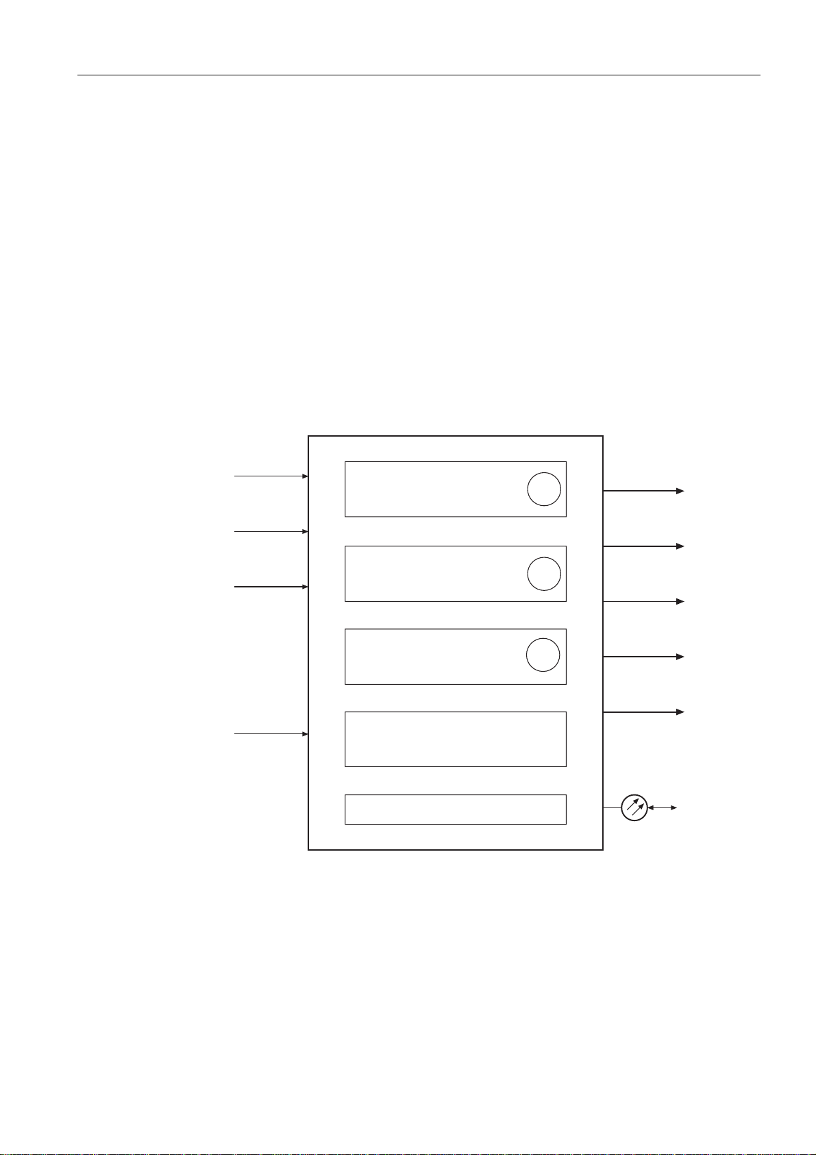
4.1.1.1 Schema of product functions ...........................................9
4.1.1.2 Overcurrent....................................................................10
4.1.1.3 Inputs.............................................................................10
4.1.1.4 Outputs..........................................................................10
4.1.1.5 Circuit-breaker failure protection....................................10
4.1.1.6 Disturbance recorder .....................................................10
4.1.1.7 MMI module...................................................................11
4.1.1.8 Self-supervision.............................................................11
4.1.2 Configuration ..........................................................................12
4.1.3 Protection ...............................................................................13
4.1.3.1 Overcurrent unit.............................................................13
4.1.3.2 Time/current characteristics...........................................14
4.1.3.3 Settings..........................................................................23
4.1.3.4 Technical data of protection functions............................30
4.1.4 Monitoring...............................................................................31
4.1.5 Self-supervision (IRF).............................................................31
4.1.6 I/O test....................................................................................32
4.1.7 Disturbance recorder ..............................................................32
4.1.7.1 Function.........................................................................32

ABB Substation Automation
Products and Systems Technical Reference Manual REJ 523
1MRS750940-MUM
3
4.1.7.2 Recorder data ...............................................................32
4.1.7.3 Control and indication of recorder status.......................32
4.1.7.4 Triggering......................................................................33
4.1.7.5 Settings and unloading..................................................33
4.1.7.6 Event code....................................................................34
4.1.8 Recorded data........................................................................35
4.1.9 External serial communication................................................35
4.1.9.1 Communication ports ....................................................35
4.1.9.2 Event codes ..................................................................37
4.1.9.3 Remote transfer data ....................................................39
4.1.10 Relay parameterization...........................................................48
4.2 Design description...........................................................................48
4.2.1 Input / output connections......................................................48
4.2.2 Serial communication connections.........................................51
4.2.3 Technical data........................................................................52
5 Ordering information.................................................................................57
6 References...............................................................................................58
7 Index/Glossary .........................................................................................59
8 Check lists................................................................................................60
9 Customer feedback ..................................................................................63

REJ 523 Technical Reference Manual ABB Substation Automation
Products and Systems
MRS750940-MUM
4
1 Introduction
1.1 About this manual
This manual is intended to provide the user with thorough information on the relay
REJ 523 and its applications. The focus in the manual is on technical description of
the relay.
Instructions for using the MMI are found in a separate “Operator’s Manual” and for
installation in “Installation Manual”.
1.2 The use of the relay
The overcurrent relay REJ 523 is designed to be used for selective short-circuit
protection in medium voltage distribution networks. The protection relay includes a
phase overcurrent unit with flexible tripping and signalling facilities. The overcurrent
relay can also be used in other applications requiring single-, two- or three-phase
overcurrent protection.
The protection relay REJ 523 is based on a microprocessor environment. A self-
supervision system monitors continuously the operation of the microprocessor.
The MMI includes an LCD display which makes the local use of the relay safe and
easy.
Local control of the protection relay can be carried out with a portable computer
connected to the front connector and remote control via the rear connector connected
to the distribution automation system through the serial interface and fibre-optic bus.
1.3 Features
•Three-phase low-set overcurrent stage with definite-time or inverse definite
minimum time (IDMT) characteristic.
•Three-phase high-set overcurrent stage with instantaneous or definite-time
characteristic.
•Circuit-breaker failure protection unit (CBFP).
•Disturbance recorder.
•Three accurate current inputs.
•Galvanically isolated binary input with a wide input voltage range.
•All settings can be modified with a personal computer.

ABB Substation Automation
Products and Systems Technical Reference Manual REJ 523
1MRS750940-MUM
5
•MMI with an alphanumeric LCD and manoeuvring buttons.
•Settings are stored into non-volatile memory and remain even in case of power
supply failure.
•Two normally open power output contacts.
•Two change-over type signal output contacts.
•Output contact functions freely configurable for desired operation.
•Optical PC-connector for two-way data communication (front).
•RS-485 connector (rear) for system communication.
•Continuous self-supervision of hardware and software. At a permanent fault all
stages and outputs are blocked.
•Rated frequency user-selectable 50/60 Hz.
•User-selectable password protection for MMI.
•Display of primary current values.
1.4 Guarantee
Please inquire the guarantee of your nearest ABB representative.

REJ 523 Technical Reference Manual ABB Substation Automation
Products and Systems
MRS750940-MUM
6
2 Safety information
!
Dangerous voltages can occur on the connectors, even though the auxiliary voltage
is disconnected.
!
National and local electrical safety regulations must always be followed.
!
The frame of the protection relay has to be carefully earthed.
!
Current transformers have to be short-circuited before disconnecting the relay from
them.
Only a competent electrician is allowed to carry out the electrical installation.

ABB Substation Automation
Products and Systems Technical Reference Manual REJ 523
1MRS750940-MUM
7
3 Instructions
3.1 Application
The overcurrent relay REJ 523 is a secondary relay that is connected to the current
transformers of an object to be protected. The three-phase overcurrent unit
continuously measures the phase currents of the object. On detection of a fault the
relay starts, trips the circuit breaker, provides alarms, records fault data etc., in
accordance with the application and the configured relay functions.
The overcurrent unit includes two protection stages: a low-set stage I> and a high-set
stage I>>. If the high-set stage is given a setting within the lower part of the setting
range, the relay module will contain two nearly identical operation stages. In this case
the relay can be used in two-stage load shedding applications.
The protection functions are independent of each other and have their own setting
groups and data recording. The overcurrent protection function uses conventional
current transformer measurement.
Output contact matrix allows any start or trip signal from the protection stages to be
routed to the desired output contact.
3.2 Requirements
When the protection relay is operating under conditions specified below (see also
“Technical data”), the relay is practically maintenance-free. The relay includes no
parts or components subject to abnormal physical or electrical wear under normal
operating conditions.
Environmental conditions
•Specified ambient service temperature range -10...+55 °C
•Temperature influence on the operating values of the
relay within the specified ambient service temperature
range
0.1% / °C
•Transport and storage temperature range -40...+70 °C

REJ 523 Technical Reference Manual ABB Substation Automation
Products and Systems
MRS750940-MUM
8
3.3 Configuration
Setting and connection examples
The appropriate configuration of the output contact matrix enables using the start
signals of the overcurrent unit as contact functions. The start signals can be used for
blocking co-operating protection relays, for signalling and for initiating autoreclosing.
Figures 3.3-1 and 3.3-2 represent the relay with the default configuration: all trips are
routed to operate the circuit breaker.
5 A
1 A
5 A
1 A
5 A
1 A
L1
L2
L3
ConD1_523
IO
+ ++
+
-
-
++
0
I
+ -
I/O
3I>
3I>>
1
2
3
SGB1
SGB1
SGB1
∼
∼
X
3
X
3
2
X
2
X
1
X
1
X
X
4
X
4
5 6 3 4
13 14 15
1 2
17 18
1 2 3 4 5 6 7 8 9
SGB1
SGB1
5
6
10 11 12 7 8 9
X2.1
X1.1
1MKC950001-1
RER 103
Tx Rx
PO1PO2
IRF
BI SO1SO2
IRF
START
TRIP
START
TRIP
SGR1
SGR2
SGR3
SGR4
PC
Uaux
REJ 523
THREE PHASE OVERCURRENT
CONFIGURATION
Optical
PC-interface
Spa Bus
INDICATORS RESET
RELAYS RESET
MEMORIZED VALUES RESET
Blocking of stage I>>
Blocking of stage I>
x = Factory Default
Figure 3.3-1 Connection diagram of the overcurrent relay
5 A
1 A
5 A
1 A
5 A
1 A
L1
L2
L3
ConD2_523
IO
+ ++
+
-
-
++
0
I
+ -
Uaux
I/O
3I>
3I>>
1
2
3
SGB1
SGB1
SGB1
∼
∼
X
3
X
3
2
X
2
X
1
X
1
X
X
4
X
4
5 6 3 4
13 14 15
1 2
17 18
1 2 3 4 5 6 7 8 9
SGB1
SGB1
5
6
10 11 12 7 8 9
X2.1
X1.1
1MKC950001-1
RER 103
Tx Rx
PO1PO2
IRF
BI SO1SO2
IRF
START
TRIP
START
TRIP
SGR1
SGR2
SGR3
SGR4
PC
REJ 523
THREE PHASE OVERCURRENT
CONFIGURATION
Optical
PC-interface
Spa Bus
INDICATORS RESET
RELAYS RESET
MEMORIZED VALUES RESET
Blocking of stage I>>
Blocking of stage I>
X = Factory Default
Figure 3.3-2 Connection diagram of the overcurrent relay

ABB Substation Automation
Products and Systems Technical Reference Manual REJ 523
1MRS750940-MUM
9
4 Technical description
4.1 Functional description
4.1.1 Product functions
4.1.1.1 Schema of product functions
50
51
IL1
IL2
IL3
PrF5_3
62 BF
PO1
PO2
SO1
SO2
IRF
SERIAL COMMUNICATION
THREE PHASE INSTANTANEOUS OR
DEFINITE TIME HIGH-SET
OVERCURRENT PROTECTION
THREE PHASE DEFINITE TIME OR
INVERSE TIME LOW-SET
OVERCURRENT PROTECTION
OPTICAL PC-INTERFACE
REMOTE RESET, REMOTE SETTING
CONTROL OR BLOCKING INPUT FOR
THE DIFFERENT PROTECTION STAGES
CIRCUIT-BREAKER FAILURE
PROTECTION
BINARY
INPUT BI
Figure 4.1.1.1-1 Product functions

REJ 523 Technical Reference Manual ABB Substation Automation
Products and Systems
MRS750940-MUM
10
4.1.1.2 Overcurrent
Refer to section 4.1.3.1 Overcurrent unit.
4.1.1.3 Inputs
The relay includes three energizing inputs for phase currents and one external binary
input controlled by an external voltage. The function of the binary input is determined
with selector switches of the protection relay. For inputs, see also section 4.2.1 Input /
output connections and tables 4.1.3.3-5, 4.2.1-1 and 4.2.1-5.
4.1.1.4 Outputs
The relay is provided with two power outputs (PO1 and PO2), and two signal outputs
(SO1 and SO2). Switchgroups SGR1...4 are used for routing the start and trip signals
of any protection stage to the desired signal or power output.
4.1.1.5 Circuit-breaker failure protection
The relay features a circuit-breaker failure protection (CBFP) unit. The CBFP unit
generates a trip signal via output PO2 after the set operate time 0.1 s...1 s if the fault
has not been cleared by that time.
Normally, the CBFP unit controls the upstream circuit breaker. It can also be used for
tripping via redundant trip circuits of the same circuit breaker if the circuit breaker is
provided with two trip coils. The circuit-breaker failure protection unit is activated
with a switch of switchgroup SGF.
4.1.1.6 Disturbance recorder
The relay includes an internal disturbance recorder, which records momentary values,
internal logic signals and external BI signal. The disturbance recorder can be set to be
triggered on operation of stages or on an external BI signal, either on the falling or
rising trigger edge.

ABB Substation Automation
Products and Systems Technical Reference Manual REJ 523
1MRS750940-MUM
11
4.1.1.7 MMI module
The MMI of the relay is equipped with six push-buttons and an alphanumeric LCD
for 2 x 16 characters. The push-buttons are used for navigating in the menu structure
and for adjusting set values.
An MMI password protects all user-changeable values from being changed by an
unauthorised person. The default value for the MMI password is “999”. With the
default value the password is not active and it is not required for altering parameter
values. For further information, refer to “Operator’s Manual”.
4.1.1.8 Self-supervision
The self-supervision system of the relay handles run-time fault situations and informs
the user about an existing fault. When the self-supervision system detects a permanent
internal relay fault, the ready indication LED starts blinking. At the same time the
self-supervision alarm relay that is normally picked up drops off and a fault code
appears on the display. This code is a number that identifies the fault type. For fault
codes, refer to section “Internal fault” in “Operator’s Manual”.
Faultc
C
E
INTERNAL FAULT
FAULT CODE : 56
STARTREADY TRIP
Figure 4.1.1.8-1 Internal fault
Fault codes can indicate:
•No response on output contact test.
•Faulty program memory, work memory or parameter memory.
•Internal reference voltage error.

REJ 523 Technical Reference Manual ABB Substation Automation
Products and Systems
MRS750940-MUM
12
4.1.2 Configuration
The figure below illustrates how the start, trip and binary input signals can be
configured so that the required protection functions are obtained.
17 18
X2.1 13 14 15 10 11 12 7 8 9 3 45 6
SDiag523
3I>
3I>>
4
5
IL1
IL2
IL3 6
4
4
4
3
3
3
3
2
2
2
2
1
1
1
1
I/O
1
2
3
BI PO1PO2SO1
IRF SO2
SGF1-3
IRF
START
TRIP
START
TRIP
SGR1
SGR2
SGR3
SGR4
SGB1
SGB1
SGB1
SGB1
SGB1
Blocking of stage I>>
Blocking of stage I>
INDICATORS RESET
RELAYS RESET
MEMORIZED VALUES
RESET
Figure 4.1.2-1 Signal diagram of the overcurrent relay
The functions of the blocking and start signals are selected with the switches of
switchgroups SGF, SGB and SGR. The checksums of the switchgroups are found in
the menu group “Settings” of the protection relay. The functions of these switches are
explained in detail in the corresponding SG_ -tables.

ABB Substation Automation
Products and Systems Technical Reference Manual REJ 523
1MRS750940-MUM
13
4.1.3 Protection
Block diagram
IL 1
IL 2
IL 3
I>
0.12 * I>
1.5 * I>
1.25 * I>
&
2 * I>>
SGF2/1
SGR3/x
SGR4/x
SGR2/x
SGR1/x
t> , k
I>>
SGB1/6
BI
SO2
t>>
SGB1/5
4
55 ms
30 ms
SO1
3
11
C
5 s
PO2
SGF1/2
2
0.1 ... 1 s
SGF1/1
C
5 s
SGF1/5
PO1
1
1
SGF2/3
1
C
I>
I>>
START
SGF1/4
1
t>
t>>
C
TRIP
SGF3/1...6
SGB1/4
SGB1/1
SGB1/2
SGB1/3
SGF1/3
40/80 ms
40/80 ms
40/80 ms
40/80 ms
SGF2/4, 5
RESET INDICATORS AND LATCHED OUTPUT RELAYS
RESET INDICATORS, LATCHED OUTPUT RELAYS AND REGISTERS
RESET INDICATORS
SETTINGS (Group 1 / Group 2)
Block5_3
Figure 4.1.3-1 Block diagram of the overcurrent relay
4.1.3.1 Overcurrent unit
When the phase currents exceed the set start current of the low-set stage I>, the
overcurrent unit starts delivering a start signal after a preset ~ 55 ms start time. When
the set operate time at definite-time operation or the calculated operate time at
inverse-time operation elapses, the overcurrent unit operates. In the same way, the
high-set stage I>> of the overcurrent unit starts delivering a start signal after a preset
~ 30 ms start time when the set start current is exceeded. When the set operate time
elapses, the overcurrent unit operates.
The low-set stage of the overcurrent unit may be given a definite-time or an inverse
definite minimum time (IDMT) characteristic. When the IDMT characteristic is

REJ 523 Technical Reference Manual ABB Substation Automation
Products and Systems
MRS750940-MUM
14
chosen, six time/current curve groups are available. Four of the groups comply with
the standards BS 142 and IEC 60255, and are called “normal inverse “, “very
inverse”, “extremely inverse” and “long-time inverse”. The two additional inverse-
time curve groups are called “RI-” and “RD-curves”.
The inverse-time function of stage I> can be inhibited when stage I>> is started. In
this case the operate time is determined by stage I>>.
If not needed, the stage I>> can be set out of operation completely. This state is
indicated by three dashes “---” on the LCD and by “999” when the set start current
value is read via serial communication.
The set start current value I>>/Inof stage I>> can be automatically doubled in a start
situation, i.e. when the object to be protected is connected to a network. Thus a set
start current value below the connection inrush current level may be selected for the
overcurrent stage I>>. A start situation is defined as a situation where the phase
current rises from a value below 0.12 x I> to a value above 1.5 x I> in less than 60 ms.
The start situation ends when the current falls below 1.25 x I>.
4.1.3.2 Time/current characteristics
The overcurrent stage I> can be given a definite-time or an inverse definite minimum
time operation characteristic. The settings of switches SGF3/1...6 determine the
operation mode of the stage. Refer to section "Settings". At the IDMT characteristic,
the operate time of the stage is a function of the current: the higher the current, the
shorter the operate time. Six time/current curve groups are available. Four of these
comply with the standards BS 142 and IEC 60255 and two curve groups, RI and RD,
are special type curve groups according to ABB praxis.
Characteristics according to IEC 60255 and BS 142
The relay module incorporates four internationally standardized time/current curve
groups called "extremely inverse", "very inverse", "normal inverse" and "long-time
inverse". The relationship between time and current is in accordance with the
standards BS 142 and IEC 60255-4, and can be expressed as follows:

ABB Substation Automation
Products and Systems Technical Reference Manual REJ 523
1MRS750940-MUM
15
t[s] = k
I
I
×
>
−
β
α
1
where t = operate time
k = time multiplier
I = phase current value
I> = set current value.
Table 4.1.3.2-1 The values of constants α and β.
Time/current curve group α β
Normal inverse 0.02 0.14
Very inverse 1.0 13.5
Extremely inverse 2.0 80.0
Long-time inverse 1.0 120
The standard BS 142.1966 defines the normal current range to be 2...20 times the
setting value. In addition, the relay has to start at the latest when the current exceeds
the setting value 1.3 times if the time/current characteristic is normal inverse, very
inverse or extremely inverse. For the long-time inverse characteristic the normal
current range is specified to be 2...7 times the setting, and the relay is to start when
the current exceeds the setting value 1.1 times.
Table 4.1.3.2-2 The operate time tolerances specified by the standard
I/I> Normal Very Extremely Long time
2 2,22E 2,34E 2,44E 2,34E
5 1,13E 1,26E 1,48E 1,26E
7 - - - 1,00E
10 1,01E 1,01E 1,02E -
20 1,00E 1,00E 1,00E -
E = accuracy in per cent; - = not specified
In the normal current range, specified above, the inverse-time stage of the overcurrent
relay fulfils the tolerance requirements of class 5 at all degrees of inversity.
The time/current characteristics according to the IEC and BS standards are illustrated
in figures 4.1.3.2-1…4.1.3.2-4.

REJ 523 Technical Reference Manual ABB Substation Automation
Products and Systems
MRS750940-MUM
16
RI-type characteristic
The RI-type characteristic is a special characteristic that is principally used for
obtaining time grading with mechanical relays. The characteristic can be expressed
mathematically:
t [s] = kII
0 339 0 236..−×
>
where t = operate time in seconds
k = time multiplier
I = phase current
I> = set start current.
The RI-type characteristic is illustrated in figure 4.1.3.2-5.
RD-type characteristic
The RD-type characteristic is a special characteristic that is principally used in earth-
fault protection which requires a high degree of selectivity even at high resistance
faults. In this case, the protection can operate in a selective way even if it is not
directional. Mathematically, the time/current characteristic can be expressed as
follows:
t [s] = 5.8-1.35 x log eI
kI
×>
where t = operate time in seconds
k = time multiplier
I = phase current
I> = set start current.
The RD-type characteristic is illustrated in figure 4.1.3.2-6.

ABB Substation Automation
Products and Systems Technical Reference Manual REJ 523
1MRS750940-MUM
17
0.05
0.1
0.2
0.3
0.4
0.5
0.6
0.7
0.8
0.9
1.0
k
12 3 4 5 7 8 9 10 20 I/I>6
0.02
0.03
0.04
0.05
0.06
0.07
0.08
0.09
0.1
0.2
0.3
0.4
0.5
0.6
0.7
0.8
0.9
1
2
3
4
5
6
7
8
9
10
20
30
40
50
60
70
t/s
NORMINV
Figure 4.1.3.2-1 Normal inverse time characteristics

REJ 523 Technical Reference Manual ABB Substation Automation
Products and Systems
MRS750940-MUM
18
12
3
4
5
678910 20 I/I>
0.05
0.1
0.2
0.3
0.4
0.5
0.6
0.7
0.8
0.9
1.0
k
0.02
0.03
0.04
0.05
0.06
0.07
0.08
0.09
0.1
0.2
0.3
0.4
0.5
0.6
0.7
0.8
0.9
1
2
3
4
5
6
7
8
9
10
20
70
60
50
40
30
t/s
VERYINV
Figure 4.1.3.2-2 Very inverse time characteristics

ABB Substation Automation
Products and Systems Technical Reference Manual REJ 523
1MRS750940-MUM
19
13
4
5
6
7
89102 20 I/I>
0.05
0.1
0.2
0.3
0.4
0.6
0.8
1.0
k
0.02
0.03
0.04
0.05
0.06
0.07
0.08
0.09
0.1
0.2
0.3
0.4
0.5
0.6
0.7
0.8
0.9
1
2
3
4
5
6
7
8
9
10
20
30
40
70
60
50
t/s
EXTRINV
Figure 4.1.3.2-3 Extremely inverse time characteristics

REJ 523 Technical Reference Manual ABB Substation Automation
Products and Systems
MRS750940-MUM
20
1234510206789 I/I>
0.05
0.1
0.2
0.3
0.4
0.5
0.6
0.7
0.8
0.9
1.0
k
0.2
0.3
0.4
0.5
0.6
0.7
0.8
0.9
1
2
3
4
5
6
7
8
9
10
20
30
40
50
60
70
80
90
100
200
300
400
500
600
700
t/s
LTIMEINV
Figure 4.1.3.2-4 Long-time inverse characteristics
Table of contents
Other ABB Relay manuals