ERL F-PRO 116 User manual

F-PRO 116
Non-Directional Multifunction & SEF Protection Relay
User
Manual
Version 1.2 Rev 0
DigitallysignedbyNorbertWegner
DN:cn=NorbertWegner,o=ERLPhasePowerTechnologies
Date:2022.01.0410:48:32-06'00'


D05125R01.20 F-PRO 116 User Manual i
Preface
Information in this document is subject to change without notice.
© 2022 ERLPhase Power Technologies Ltd. All rights reserved. Reproduction in any
manner whatsoever without the written permission of ERLPhase Power Technologies
Ltd. is strictly forbidden. This manual is part of a complete set of product
documentation that includes detailed drawings and operation. Users should evaluate
the information in the context of the complete set of product documentation and
their particular applications. ERLPhase assumes no liability for any incidental,
indirect or consequential damages arising from the use of this documentation.
While all information presented is believed to be reliable and in accordance with
accepted engineering practices, ERLPhase makes no warranties as to the
completeness of the information.
All trademarks used in association with L-PRO, T-PRO, F-PRO, B-PRO, S-PRO, TESLA,
iTMU, TESLA Control Panel, Relay Control Panel, RecordGraph, RecordBase and
ProLogic are trademarks of ERLPhase Power Technologies Ltd.
Windows® is a registered trademark of the Microsoft Corporation.
HyperTerminl® is a registered trademark of Hilgraeve.
Modbus® is a registered trademark of Modicon.
Contact Information
ERLPhase Power Technologies Ltd.,
Website: www.erlphase.com
Email: info@erlphase.com
Technical Support
Email: support@erlphase.com
Tel: 1-204-477-0591
ii F-PRO 116 User Manual D05125R01.20
Using This Guide
This User Manual describes the installation and operation of the F-PRO Multifunction Protection
Relay. It is intended to support the first time user and clarify the details of the equipment.
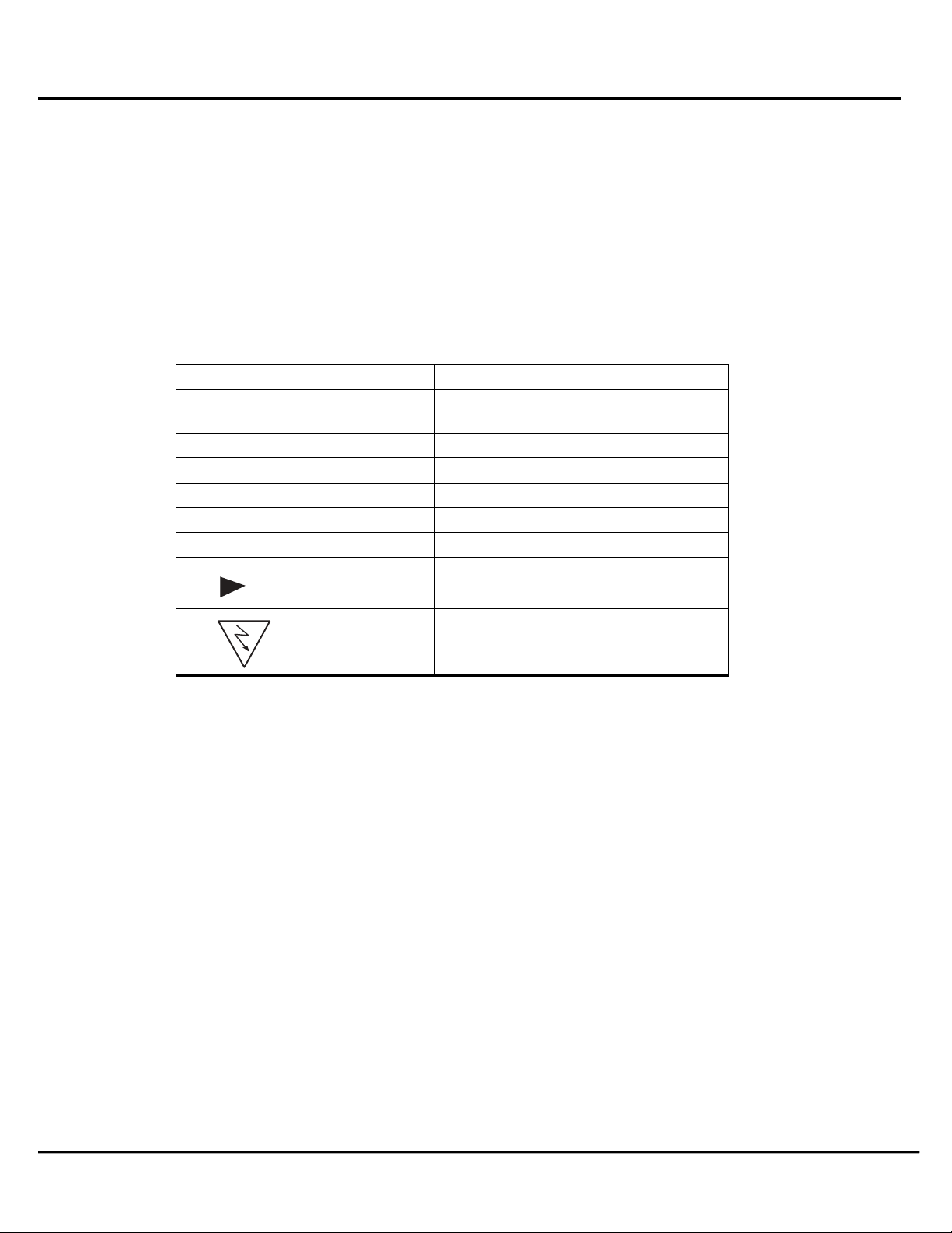
The manual uses a number of conventions to denote special information:
Example
Describes
Start>Settings>Control
Panel
Choose the Control Panel submenu in the
Set
tings submenu on the Start menu.
Right-click
Click the right mouse
butt
on.
Recordings
Menu items and tabs are shown in italics.
Service
User input or keystrokes are shown in bold.
Text boxes similar to this one
Relate important notes and information.
..
Indicates more screens.
Indicates further drop-down menu,
click to display list.
Indicates a warning.

D05125R01.20 F-PRO 116 User Manual iii
Table of Contents
Preface ……………………………………………………………………………….….….. i
Contact Information...…………………………..……………………………………… i
Using this Guide ………………………………………………………………………….… ii
Table of Contents ……………………….…………………………………...…………… iii
Acronyms …………………………………………………………………………….…….. v
Version Compatibility …………………………………………….…………………….. vi
PC System Requirements and Software Installation …………………….. vii
1. Overview
1.1 Introduction …………………………………....……….……….……..……….... 1-1
1.2 Front View ………………………………………..………………….....…....……. 1-3
1.3 Rear View ……………………………………………………….………….…........ 1-4
1.4 Model Options/Ordering ……….………………………………......…….... 1-5
2. Installation and Safety Instructions ......................................... 2-1
2.1 Introduction ............................................................................. 2-1
2.2 Physical Mounting..................................................................... 2-1
2.3 Power Supply............................................................................ 2-2
2.4 AC and DC Wiring...................................................................... 2-2
2.5 Communication Wiring............................................................. 2-2
3. Setup and Communication
3.1 Power Supply ……………………..……………………………………………….. 3-1
3.2 USB Link …………………………………………………………………………….…. 3-1
3.3 Accessing the Relay’s SCADA Services ………………………………...…3-3
3.4 Communication Port Details ………..……………………………………..… 3-4
3.5 Time Source.……………………………………....................................... 3-5

iv F-PRO 116 User Manual D05125R01.20
4. Using the IED (Getting Started)
4.1 Start-up Sequence …………………………………………………………………. 4-1
4.2 Front Panel Display ……………………………………………………………..…. 4-1
4.3 Terminal Interface………………………………………………………............. 4-7
5. Protection Functions and Specifications
5.1 Current Protection Functions………………………………………………….. 5-1
5.2 Monitoring Functions……………………………………………………………... 5-17
5.3 Control Functions…………………………………………………………………… 5-18
5.4 ProLogic…………………………………………………………………………………. 5-19
5.5 Group Change Control Statement………………………………………….. 5-20
5.6 Event Log……………………………………………………………………………….. 5-21
5.7 Fault Log………………………………………………………………………………… 5-21
6. Data Communications
6.1 Introduction………………………………………………………………………….. 6-1
6.2 SCADA Protocol………………………………………………………………..…… 6-1
7. Settings and Analysis Software
7.1 Offliner Setting Software ………………………………………………………. 7-1
7.2 Offliner Features ……………….………………………………………………….. 7-2
7.3 Offliner Keyboard Shortcuts …………….……………………………………. 7-4
7.4 Handling Backward Compatibility ………..…………………………….…. 7-5
7.5 Main Branches from the Tree View ………….………………………..…. 7-7
8. Acceptance Test Guide
8.1 Acceptance Testing ……………………………………………………………….. 8-1

D05125R01.20 F-PRO 116 User Manual v
Appendix A IED Specifications …………….………………………………………..……..….. A-1
A.1 IDMTL Element OperatingTime Curves ………………………….………. A-5
Appendix B IED Settings and Ranges ……………………..……………………..…………. B-1
Appendix C Hardware Description …………………………..………………….…………… C-1
Appendix D Event Messages ………………………….………………….………….………….. D-1
Appendix E Modbus RTU/ ASCII Communication Protocol ……………….…….….………. E-1
Appendix F IEC 103 Device Profile ………………………………………………..…………… F-1
Appendix G DNP3.0 Device Profile……………………………………………………..……… G-1
Appendix H Mechanical Drawings ……………………………………………….….………… H-1
H.1 Front View ………………………………….…………….……………..……………. H-1
H.2 Rear View ………………………………….…………….……………..…………….. H-2
Appendix I AC Schematic Drawing ……………………….…………………….…………… I-1
Appendix J DC Schematic Drawing …………………………………………….…………… J-1
Appendix K Connection Diagram……………………………….……………………………. L-1
Appendix L F-PRO Setting Example ………………………….………………………………. M-1

vi F-PRO 116 User Manual D05125R01.20
Acronyms
CT - Current Transformer
DCE - Data Communication Equipment
HMI - Human Machine Interface
IEC - International Electro-technical Commission
IED - Intelligent Electronic Device
LED - Light-emitting Diode
LCD - Liquid Crystal Display
LHS - Left Hand Side
RHS - Right Hand Side
SG - Setting Group
UI - User Interface

D05125R01.20 F-PRO 116 User Manual vii
Version co
mpatibility
This chart indicates the versions of Offliner Settings, this User Manual was created using the
following software and firmware versions.
Offliner Settings are backward compatible with all earlier versions of setting files.
F-PRO Firmware/Software Compatibility
Guide
F-PRO Firmware
Setting
Version
Compatible Offliner
Settings
V1.2
2
V3.1
Please contact ERLPhase Technical support for complete Revision History.

viii F-PRO 116 User Manual D05125R01.20
PC System Requirements and Software Installation
Hardware
The minimum hardware requirements are:
•1 GHz processor
•2 GB RAM
•20 GB available hard disk space
•USB port
•Serial communication port
Operating System
One of the following operating systems must be installed and functional prior to installing the
applications:
•Microsoft Windows 7
•Microsoft Windows 10
ERLPhase software requires a minimum of Windows 7 OS.
Software Installation
All required software for user interface and settings (F-PRO Offliner) are available directly from
the ERLPhase website: www.erlphase.com. The following relevant software and documentation
is available:
•F-PRO Offliner: Software
•USB STM32 –VCP Driver for F-PRO 116: Software (not required for Windows 10)
•Relay User manual: Manual in PDF format
To Install Software on the Computer
To install the software on the computer, click the desired item on the screen. The installation
program launches automatically. Installation may take a few minutes to start.
A terminal software (HyperTerminal for example) and USB STM32 VCB driver also to be installed.
Anti-virus/Anti-spyware Software
If antivirus/anti-spyware software on user local system identifies any of the ERLPhase applications
as a “potential threat”, it will be necessary to configure user antivirus/anti-software to classify it
as “safe” for its proper operation. Please refer the appropriate antivirus / anti-spyware software
documentation to determine the relevant procedure.

D05125R01.20 F-PRO 116 User Manual 1-1
1 Overview
1.1 Introduction
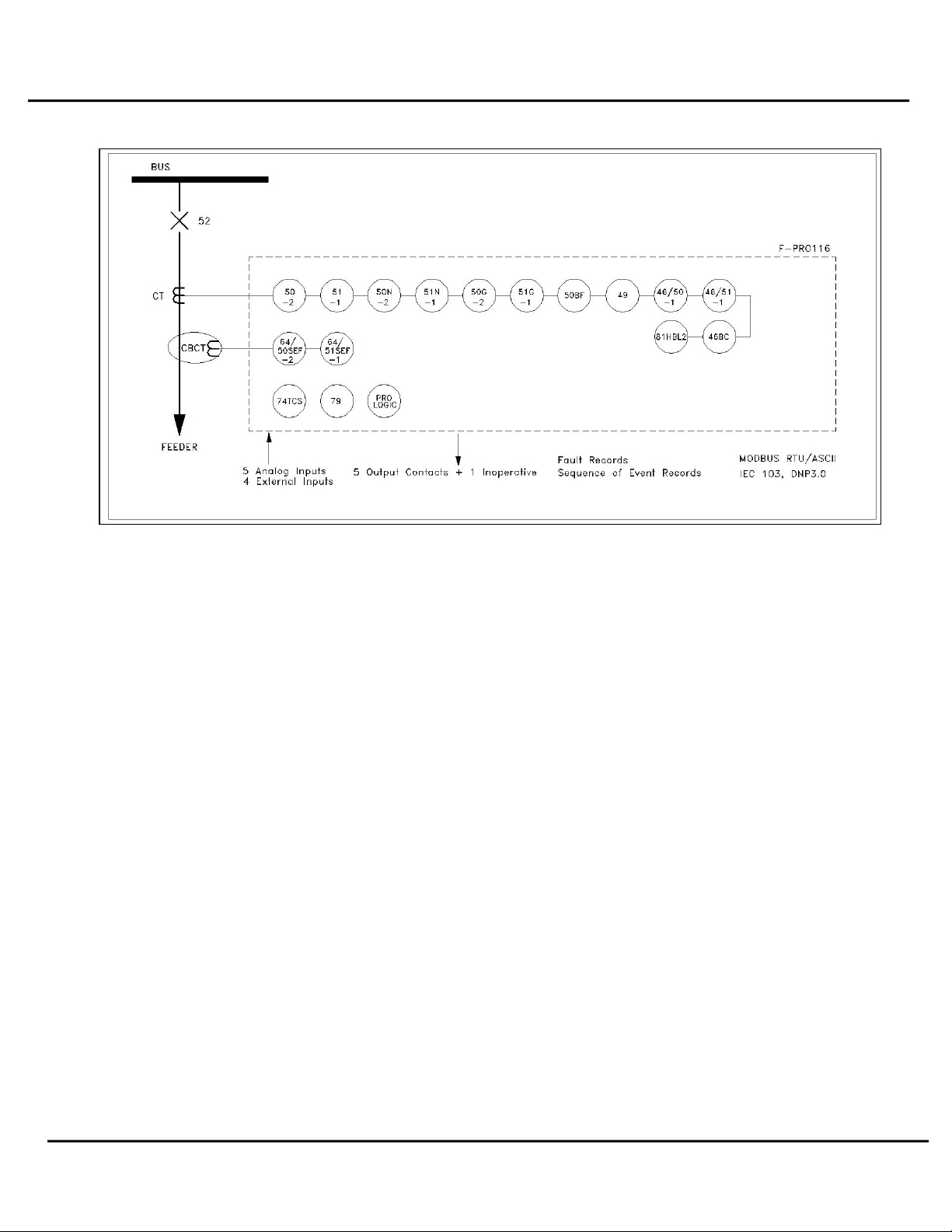
The F-PRO 116 is a microcontroller-based relay providing comprehensive protection for
Overcurrent, Earth Fault, Sensitive/Restricted Earth Fault, Auto-Reclosing, Circuit Breaker Failure,
Broken conductor, Thermal Overload and Negative Sequence Overcurrent. Inrush Restraint, Trip
Circuit Supervision, Metering and Breaker Monitoring functions suitable for distribution
applications are also provided.
Terminal software, such as HyperTerminal, enables the user to:
•Change & retrieve relay settings
•View event and fault information
F-PRO Offliner is the offline tool which enables the user to create, modify and review relay
settings.
The primary protection provided is overcurrent based. A library for these overcurrent functions
provides commonly used IEEE and IEC inverse curves. Since the curves are equation-driven, the
user can choose to enter equation parameters directly to create user defined overcurrent curve
shapes as needed.
To provide a complete package of protection and control, the F-PRO 116 provides other functions
such as:
•Breaker failure Protection (50BF)
•Broken Conductor (46BC)
•Thermal Overload (49)
•Multi-shot Auto Recloser (79)
•5 ProLogic statements
•2 Setting Groups
1-2 F-PRO 116 User Manual D05125R01.20
Figure 1.1: F-PRO 116 Relay Function Line Diagram

D05125R01.20 F-PRO 116 User Manual 1-3
1.2 Front View
Figure 1.2: F-PRO Front View
Navigation controls allow
for an easy experience
through settings, change,
service and view menus.
Programmable target LED’s
provide tripping/alarm
information to expedite
response to systems events.
Handle to draw out the
relay from case.
Front panel USB port
provides easy and fast access
to settings and set up
Enter to menu &
sub-menu
Back/close button
1-4 F-PRO 116 User Manual D05125R01.20
1.3 Rear View
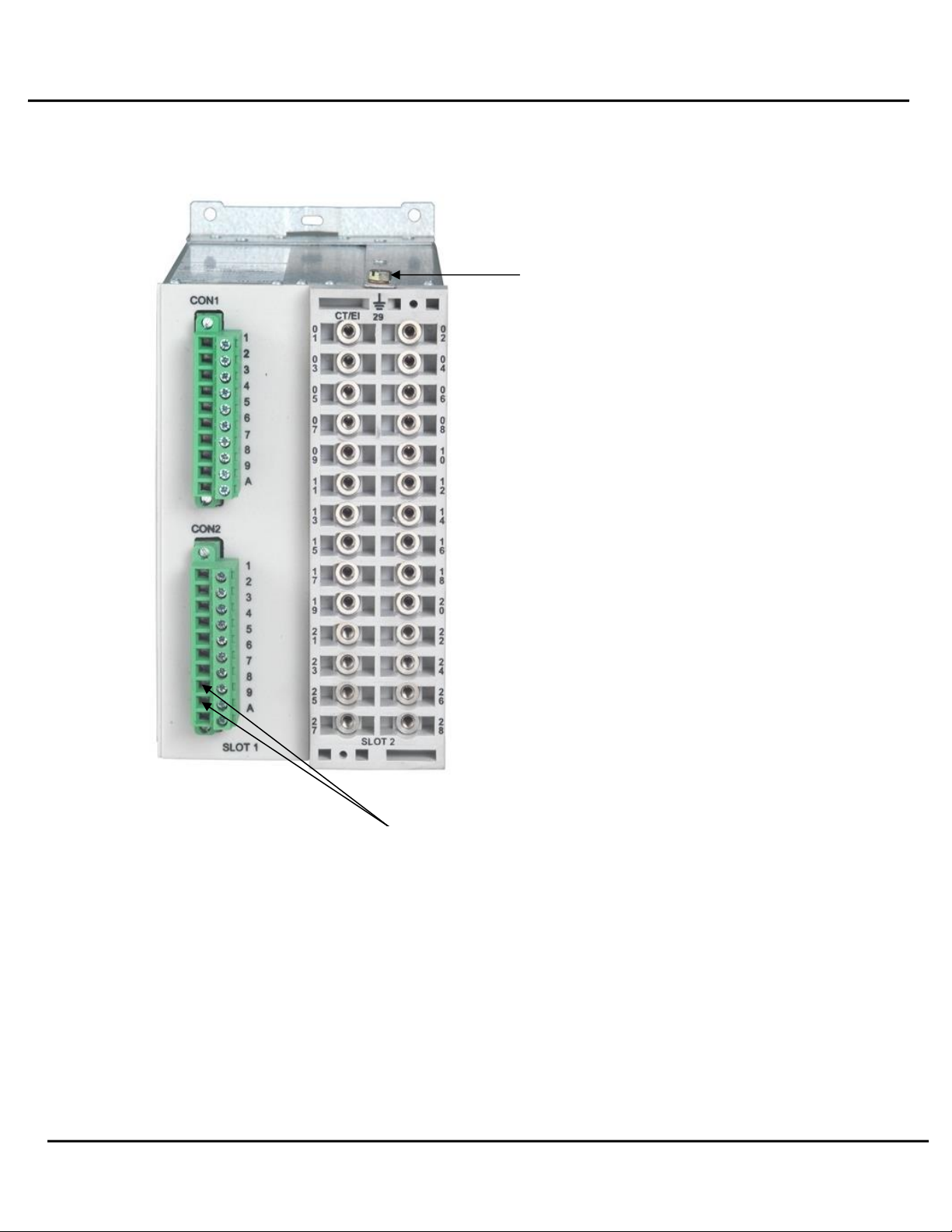
Figure 1.3: F-PRO Rear View
Case Grounding
RS-485 terminals for SCADA communication
(MODBUS and IEC103)

D05125R01.20 F-PRO 116 User Manual 1-5
AC Current Inputs
F-PRO is provided with terminal blocks for up to 5 AC current
inputs (3 Phase Current, 1 Neutral and 1 SEF). 1A and 5A are
separate terminals, 1A / 5A CT Secondary is Site Selectable.
To refer the complete schematic circuits; see “AC Schematic
Drawing” in Appendix-I & “DC Schematic Drawing” in Appendix-J
External Inputs
The F-PRO relay has 4 external inputs with a factory selectable
voltage level. External DC voltages of either 24/30 volts, 48/50
volts, 110/125 volts or 220/250 volts nominal are available
depending on the ordering code.
Relay Inoperative Alarm
Output
If the relay becomes inoperative, then the Relay Inoperative Alarm
output contact closes. Output Contact 6 may be configured as
Relay Inoperative Alarm Contacts. During the relay inoperative
period, all tripping functions are blocked.
Output Relay Contacts
The F-PRO relay has 6 output relay contacts. Each contact is
programmable and has breaker tripping capability. All output
contacts are isolated from each other. All the contacts are
provided with settable dropout timers (0-1 sec) - applicable for
self reset.
If function reset time & the output contact reset time both are set
in the IED; then, the higher value will be taken for relay drop out.
Example: 51 function is chosen with reset DTL delay 0.5 sec and
the output contact dropout time is 0.8 sec, then 0.8 sec will be the
dropout time of the output contact.
1.4 Model Options/Ordering
•The relay is available in E4 size and flush mount type along with standard for details
see “Mechanical Drawings” in Appendix-H.
•The external inputs are 24/30, 48/50, 110/125 or 220/250 Vdc rated. The Auxiliary
supply is 20-60 Vdc or 80-300 Vdc rated.
•All of the above options must be specified at the time of ordering.

1-6 F-PRO 116 User Manual D05125R01.20
Figure 1.4: Ordering Template

D05125R01.20 F-PRO 116 User Manual 2-1
2 Installation and Safety Instructions
2.1 Introduction
This section deals with the installation of the F-PRO 116 when first delivered. The section covers
the physical mounting, AC and DC wiring and the Communication wiring.
The following symbols are used in this manual and on the unit. They should be understood before
working on the unit:
Caution: refer to equipment documentation
Caution: risk of electric shock
Protective Earth (or Ground) Terminal
Auto ranging power supply
Both direct and alternating current
2.2 Physical Mounting
The relay is 177mm high, 175mm deep and 103.5mm wide. A complete mechanical drawing is
shown, for details see “Mechanical Drawings” in Appendix H. To install the relay the following is
needed:
•E4 cutout (97 x 159 mm)
•M4 screws and nuts
The equipment ratings, operating instructions and installation instructions shall be checked
before commissioning or maintenance. It is the responsibility of the user to ensure that the
equipment is installed, operated and used for its intended function in the manner specified
in this manual. If this is not the case then any safety protection provided by the equipment
may be impaired.

2-2 F-PRO 116 User Manual D05125R01.20
Case Grounding
2.3 Power Supply
A wide range power supply is standard. The relay power supply is provided with nominal operating
ranges of:
•20 to 60 Vdc
•80 to 300 Vdc / 100 to 250 Vac, 50/60 Hz.
To protect against a possible short circuit in the supply use an inline fuse or circuit breaker with a
5A rating. Ensure that the chassis is grounded for proper operation and safety.
There are no power switches on the relay. When the power supply is connected, the relay starts
its initialization process and takes about 5 seconds to complete the startup and for the green relay
functional LED to turn on.
2.4 AC and DC Wiring
For details see “AC Schematic Drawings” in Appendix I and “DC Schematic Drawings” in Appendix J.
2.5 Communication wiring
The relay user interface and supervisory control and data acquisition (SCADA) services are accessed
by:
•COM1 - Front USB 2.0 interface (user interface and maintenance)
•Rear panel serial link (RS485 serial link for Modbus, IEC103 and DNP3)
The relay user interface is accessed through terminal software such as HyperTerminal.
WARNING!
Ground the relay to station ground using the Case-Grounding terminal at the
back of the relay, for details see Figure 1.3: F-PRO Rear View on page 1-4.
Ensure the power supply input and the AC and DC wires are de-energized before
working on the wiring. Failure to do so could result in electric shock. CT circuits
shall be short-circuited before working on the current input wires.
Shielded wire shall be used for all connections that run outside of the panel in which the
F-PRO is installed. The shield must be grounded only at one end at the point where the
cable enters the panel.

D05125R01.20 F-PRO 116 User Manual 2-3
EIA-485
The relay’s serial port (COM 2) is an EIA RS-485 Data Communications Equipment (DCE)
device. This allows them to be connected directly to other relays in parallel and
communicated to a PC serial port with a standard straight-through male-to-female serial
cable with RS-485 to RS232 convertor. RS 485 cable can work for maximum 1.2KM with
single IED. Shielded cable is recommended, for pin –out see “Communication Port Details”
USB
COM 1 on the front panel is a standard USB-B connector. This port is the Maintenance port
of the relay. This is a USB 2.0 Full Speed interface and can be connected to a PC with a
standard USB peripheral cable (A style to B style).

Other manuals for F-PRO 116
1
Table of contents
Other ERL Relay manuals


Popular Relay manuals by other brands

Elektrotechnik Schabus
Elektrotechnik Schabus 300747 operating instructions

Siemens
Siemens 7VK512 instruction manual

Intellitec
Intellitec Battery Disconnect BD0 installation manual

teko
teko ASTRA-BPA user guide

Siemens
Siemens 3TK2853 quick start guide

VAMP
VAMP VAMP 55 Installation, operation and configuration instructions

Pilz
Pilz PNOZ s6 operating instructions

Deif
Deif uni-line Series Installation and start-up instructions

Schweitzer Engineering Laboratories
Schweitzer Engineering Laboratories SEL-787-3 manual

Pilz
Pilz PNOZ 1 Technical instructions

Panasonic
Panasonic IC Drivable PC Board instruction manual

LEGRAND
LEGRAND Celiane 673 91 installation instructions


