ERL AQUAMIST HFS-5 User manual

Instruction manual v3w1
FIDC tracking water injection system
GETTING TO KNOW THE AQUAMIST HFS-5
Over the last few years, demand for great engine power output is increasing. Cubic inches option is
no longer the norm. Squeezing out 200-300hp per litre is within the reach of the ordinary folks on the
street. The tuning industry has grown to embrace new tuning technique as well as readily affordable
components to produce powerful and reliable engines.
We, at Aquamist has also coming to terms with the inevitable, meeting the demands of the market
and offering new systems capable of supporting engine power output up to 1000+ BHP.
The HFS-5 reads the duty cycle of a fuel injector and delivers water proportional to fuel flow. Wate
r
quantity is metered by a High speed inline valve and flow is monitored by a turbine flow sensor.
For clogged jet and severed hose. A number of options are available for the user to limit engine
power in the absence of water flow.
We believe the HFS-5 meets all the requirement of a high-end water injection system for achieving
fast engine transient and responses with absolute precision. Tracking the fuel delivery is the most
reliable method to deliver your fluid flow under the whole engine operating cycle. Anything short o
f
this means having to tailor your fuel map to compensate the irregular fluid quantity ingested by the
engine.

Page 3
Contents:
System overview Page
3 Checking the contents of the box
4 Getting started on installation
J
unction Box
5 Junction box pin-out description
6 Flow Sensor
HFS/DDS3
7-8 HFS-5/DDS3 Dash Gauge Functions
9 Powering the system up for the first time
10 Failsfe with a number of options
Failsafe:
11 Boost control / MAP switch
Wiring: 12 Jet sizes & Advanced delivery management
13 Final check-up and setting up the failsafe
14-16 Generic wiring for PWM and MPS mode
Appendix:
17 Electrical / Mechanical specifications
18 Wiring details Guarantee and Warranty
This is a “must do” immediately
after unpacking ....
Water pump
Unpack the corrugated sheet carefully. The pump
should be labelled with the original custom Shurflo/
Aquamist part #8030 912 239 .
The white box
♦6M of 6mm OD nylon hose (806-261)
♦2M of 4mm OD nylon hose (806-266)
♦15A Fused water pump harness with 40A relay
♦75mm stainless hose clip and support bracket
♦HSV with 6/4 mm hose connector and clips and
2-way sealed plug and socket set (806-244)
♦0.8 mm water jet (806-323) in plastic bag
♦0.9 mm water jet (806-324) in plastic bag
♦1.0 mm water jet (806-325) in plastic bag
♦1x 4mm Y-piece (806-362) in plastic bag
♦2x M8 x 1/8 BSP jet adaptor with plug (806-357)
♦FIA2 (806-441) module with HFS-5 harness -3A
FUSE
♦1x water tank adapter 1/8 BSP (806-270) + 6mm
qck-fit elbow (806-376)
♦100 micron inline water filter (806-257)
♦4x M5x 40mm, nuts, washers and fasteners for
pump
♦1x M6 grounding stud with washed and nuts
and 6mm eyelet for pump ground
♦5-port brass manifold with 3/8BSP adapter. 3x
blanking plugs, 1x 3/8 BSP-M to 1/8BSP-F adap-
tor 2x 6mm 1/8BSP-M elbow.
♦1x 22cc surge arrestor/accumulator (806-409)
♦1x Pump label
DDS3v8 fluid monitoring system box
♦Assortment of 22 AWG coloured hook-up wires
♦1x DDS3 Dash Gauge with 1.5 M x 8-way cable
♦1x Version 8 Junction box
♦1x water level switch with connector (806-280c)
♦1x Digital flow sensor (806-428)
♦A set of wires for inter-connection
Note: Please contact your supplier immediately should yo
u
discover any missing parts.
Checking the contents of the box carefully
Page 2

Page 4
Page 5
Before installations guidelines
♦The pump and water tank is designed to be fitted
in the trunk. Install the water pump and inline
filter below the water tank.
♦Ensure all fittings are tighten and leak proof
before filling up with methanol, test it with water
first. If high concentration of methanol is used,
please vent the tank’s breather hole externally.
Methanol is poisonous at high concentrations.
Assembling the pump in steps
♦Gently assemble the two 3/8 BSP adapters into
the pump without crossing the threads. The
female one going into the inlet of the pump.
Flow direction is moulded onto the plastic pump
head. Ensure o-ring is properly seated.
♦Ensure the accumulator lies horizontally after
final tightening.
♦Assemble the accumulator supporting bracket
with the metal band supplied.
♦Assemble the rest of the 1/8 BSP elbow fittings
and blanking plugs. Ensure all o-ring type fittings
are not overly tightened.
♦Mark (dyes smeared on the bottom of the
pump’s rubber feet) and drill four holes for the
pump.
Water tank components
♦
Ensure the outlet is facing the rear or the side of
the tank. Drill/bore a burr-free 7/8“hole. Clear up
all the burred edges and wash the tank thor-
oughly. No debris or plastic shaving should re-
mained in the delivery system. 1-2 inch from the
bottom of the tank is ideal.
♦
Same size hole for the water level sensor. Do not
place the sensor near the washer pump, it will
not operate properly. The float should swing up-
wards. Tank venting hole must be re-directly
externally if high alcohol concentration is used.
♦A tall and slim water tank is ideal for this type of
application. Minimise delivery surge problems at
low water level.
Getting started on installation
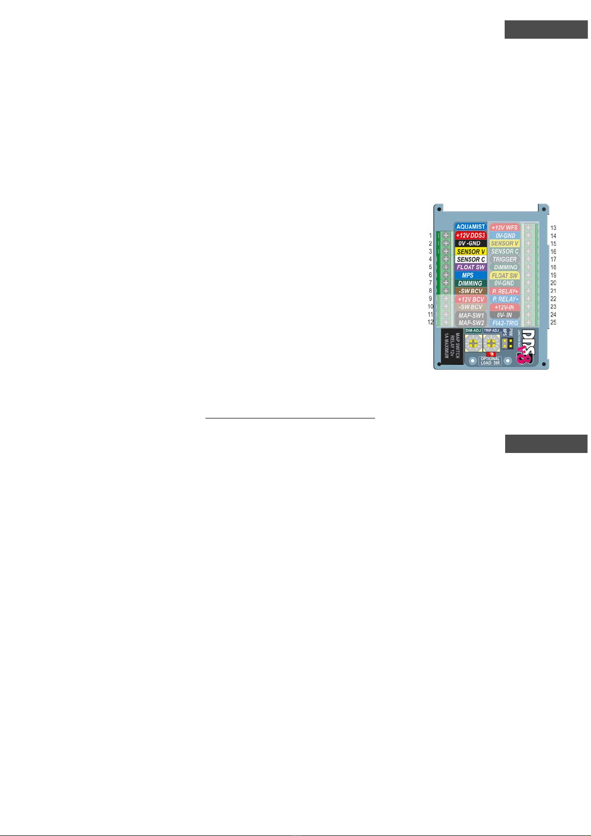
Pin1-8
Legends are colour matched and
connects directly to DDS3 Gauge
via a 8-core cable.
Pin 9-10
It will activate a wastegate sole-
noid valve directly when correct
water flow is detected (system
on). Pin 9 is a fused +12Vand
Pin10 Switches to ground.
Pin 11-12
This relay output can be used to
disconnect the OE boost control
valve and switch to a “Dummy
load resistor” to prevent “engine
check lamp” activation. “Dummy
Load Resistor” is supplied can be
soldered in. It can also be used to
switch pre-defined MAP on a third party EMS, if
available. Open circuits under fault or “DDS3-OFF”.
Pin 13-16
Flow Sensor connections, colour matched.
Pin 17
Failsafe triggering input. PWM or MPS (mode) -
section by jumper link at the bottom of the board.
Pin 18
To car’s +ve of parking lamp circuit to enable “DIM-
ADJ” potentiometer on the DDS3 junction board
Pin 19-22
To water level switch and priming pump
relay (up to 0.2A). Pin 22 switches to
ground on activation when pin 17 is
triggered.
Pin 23
Main +12V power supply to the DDS3.
Wired to the Fuel injector’s +ve supply.
Pin24
To 0V, Battery negative or chassis
ground with good electrical contact.
Pin25
FIA2 Fuel injector amplifier trigger in the
absence of manifold pressure switch or
FIDC (fuel injection duty cycle) trigger is
preferred. (for Aquamist use only)
TRIP ADJ potentiometer
Setting failsafe tripping range between 25 to 75% full
scale of the signal seen at pin 17.
DIM ADJ potentiometer
Adjust display/backlit intensity on the gauge for night
driving conditions.
MPS/PWM jumper link.
Selecting mode of operation: the WI system can be
triggered by either Manifold pressure sensor (MPS)
or fuel injector’s Duty cycle (PWM). Adjustable be-
tween 12% to 72% via “TRIP ADJ”
Junction box pin-out description

Page 6
Page 7
Flow Sensor
The standard sensor has a 1/8BSP (parallel
thread) female port on each end. Do not use 1/8
NPT fitting male thread as the tapped thread may
crack the ports. Use a 1/8BSP(M) to 1/8NPT(F)
adaptor to convert the fitting if the hose you are
using is not the same as the Aquamist type
(4mm and 6mm OD). The sensor is bi-directional
but do not change flow direction after long period
of usage unless the two internal disc filters are
properly cleaned. The sensor is suitable for use
with water or methanol at any concentration.
Sensor is fitted with 1/8BSP 4mm qck-fit hose
connectors from factory.
The DDS3 junction board supplied all the neces-
sary electrical power and signals to and from the
sensor via a 4-core cable. Length can be extended up
to 20 feet without any loss of accuracy.
Diagram below show the pin-out and functions of the
DDS3 terminals. Sensor V refers to the actual flow
signal from the sensor. Sensor C is for internal
reference use only. If you need to data-log the flow
rate, take the signal form the Sensor V terminal.
Do not install the
sensor near any mag-
netic radiated de-
vices such as ignition
coil, motors or sole-
noids because it in-
terferes with the hall
effect sensor that
reads the turbine
speed. Avoid areas
with high heat and
vibrations. A cool and
dry location is ideal.
Never reverse the
polarity of the power
feed to the sensor or
permanent damage may occur.
1. 8-element Bargraph Display (80-1200ml/min)
Each segment is equivalent to 50ml/min. of flow if the
sensor is calibrated for absolute mode.
Depends on user preference, the display can be scaled
to suit the liquid flow up to 1 litre per minute. (see 5)
2. “S” indicates the presence of sensor.
The letter “S” (sensor) must be lit after power up and
stay on to show the sensor is functioning correctly.
3. Water injection ON led
This led comes on the when the dash button is de-
pressed, showing the water injection system is enabled.
.
It will switch to full brightness when the DDS3
is triggered. (Pin 17)
4. Water Level Sensor led (yellow)
When the water level in the tank is below the
sensor, this led will light up and disables the
water injection as well as any other related
functions such as high boost, priming pump
and main pump.
5. SC (Sensor Calibration)
20-stepped potentiometer allow user to scale
the flow sensor to give an ideal visual indication
of a given flow rate. Ideally set the full scale of
the sensor about two/three segments below
maximum so a problem is easier to identify. It
can also be used to trim the sensor to show a
absolute or relative values for a particular set up.
6. Backlit flow legend
Fixed scale to indicate absolute flow rate.
Sensor must be calibrated for each application
for accuracy - scale will be updated .
7. “B” Boost Enabled led
This led lights up to show the “extended
boost” over wastegate is triggered. Provided
the following conditions are met: “Water Injec-
tion On” button is depressed, flow-rate is in-
side the set window and water tank is above
the set level.
1
2
3
5
7
10
9
8
6
4
HFS-5/DDS3 Dash Gauge Functions
Page 9
Page 8
8. Water injection enable button
Due to extra power level achieved under WI, user
want may want to reduce the power to the wheels
in less than ideal driving conditions. Disabling the WI
will reduce boost to wastegate bleed valve setting (if
fitted) as well as switching to a less aggressive MAP
on custom engine management.
9. Over-range setting potentiometer
It is just as important to monitor over-range condi-
tions as well as under-range flow conditions. If a leak
develops close to the water jet and starves the
engine of the water, the user must know this condi-
tion. A 20-stepped potentiometer allows accurate
and repeatable adjustment range.
10. Under-range setting potentiometer
This setting can indicate partial blockage and trapped
air inside a delivery hose. Again a 20-stepped poten-
tiometer is employed.
NOTE: The two range potentiometers “9”and“10”
form the basis of a SOA (Safe Operating Area) that
allow users to tune their car more safely.
Please note that methanol has only 80% mass of
water and 50% latent heat of water. If water and
alcohol mix is injected, allow a bigger jet to compen-
sate this. This is a common mistake often made.
Every 25% of methanol added should allow a 0.1mm
Increase of jet size diameter.
Installation
The gauge will fit into any 52mm gauge pod and a
two-prong bracket is provided. Do not over-tighten
the thumb-wheel since it has an embedded o-ring to
create high friction between the surfaces thus pre-
venting loosening due to vibrations.
An open ended 8-core cable is provided for connect-
ing the gauge to the junction box where all the other
sensors and peripheral devices are terminated. We
avoid using plug/socket termination because it is
difficult to thread them through the firewall between
the engine bay and pas-
senger compartment
All the core colours are
coded and matched to
the legends in front of
the terminal block, this
helps to avoid any acci-
dental termination er-
rors. The wires should
be stripped and twisted
before inserting into the
terminal blocks. The
eight top left terminals
are reserved for the
DDS3 gauge.
Powering the system up for the first time
The HFS-5 is setup as PWM-triggered mode
from factory, ie, when the fuel duty cycle has
reached a preset %, the water injection com-
mences. Please check the DDS3 junction box set to
“PWM” on the jumper link.
Step 1: Powering up the system
Disconnect the hose from the water jet and locate
it into a container, Ignition key on #1 & 2, the pump
should remain idle. Switch the DDS3 on via the
dash gauge button, again the system should remain
idle, Two leds should illuminate - “S” and “water
injection” Start the engine,
Step 2: FIA2
If the FIA2 is wiring and reading the fuel duty cycle
correctly, the green led should illuminate after the
engine is fired up and not before. You should see a
faint pulse following the engine RPM. The red led
should not illuminate at this stage.
Step 2: Manually triggering the DDS3 J.Box
Locate the “TRIP ADJ” potentiometer and turn it
fully counter-clockwise. At 12% injector duty cycle
(IDC) the WI should commence.
Blip the throttle to induce more IDC, you should see
the red led below the potentiometer lights up.
Repeat it several times to confirm this.
Step 3: Check the rest of the system.
Upon the triggered period, you should check the
following peripherals are receiving the correct signal
from the DDS3 Junction board.
1. The red led on the FIA2 illuminates
2. The “water injection” led on the gauge should get
brighter.
3. The HSV should click and buzz.
4. The water pump should turn on,
All above conditions should revert back after trig-
gered period is over.
5. The DDS3 bargraph should register flow.
Make a note of anyone of the item/items did not meet the
above conditions,contact Aquamist or your Supplier.
Step 4: Final check-up before going for a drive
Repeat the throttle blipping until all the air is purged
out of the system. You should see a continuous
stream of water coming out of the hose every time
you blip the throttle, purging is now completed.
Adjust the “TRIP ADJ” to mid way, reconnect the
hose to the jet take the system for a test drive.
You have successfully installed the system. The
system can also be triggered by manifold pressure
by relocating pin 17 to a map sensor and set
to“MPS”.

Page 10
Page 11
Failsfe with a number of options
Assuming the system is running reliably and
worked properly without any issues. Implementing
the failsafe option is the next step. The DDS can
offer a number of options to be integrated into an
existing set up so that the engine can receive ade-
quate protection when water injection flow is inter-
rupted. Pin 9 to 12 is dedicated for this purpose
Standard factory car with boost controller:
Most turbo cars from the factory runs rich under
boost conditions. With the help of a boost controller,
you can utilise those excess fuel for power by rais-
ing the boost pressure. Water will be injected to
replacing those excessive fuel. This is a very cost
effective power enhancement modification. Wiring
schematics for such a usage. (See page 16)
Standard factory car with light modifications:
Boost pressure is raised, Ignition and fuel map is
modified by either of a off-the-shelf Rom chip re-
placement or a reflash. Water injection is used to
assist in-cylinder intercooling and knock suppression.
On those set up, cutting boost to wastegate pres-
sure is ideal, in the event of water flow being inter-
rupted. (see page 14)
Standard factory cars with piggyback modifications:
Piggyback ECU is another tuning option. In general,
Signal from a load sensor is intercepted and modi-
fied before pass it to the existing engine manage-
ment. These modification can be quite involved at
times. For those applications, dropping the boost is
the simplest option. Some high-end system offer
several user selectable octane-compensated maps
but it is rare switch-able “on the fly”.
Factory EMS replacement with third party EMS:
This can possible be the most ideal set up for water
injection. A dedicated input switch allow instant pag-
ing of alternative map in the event of water flow fault.
Boost control / MAP Switch
The DDS3 can perform a few useful functions
to enable the engine to run leaner and more timing
advance with minimum of risk to the engine. In
return for some extra power and torque. Details of
how this can be achieved are listed below.
Equipped with two outputs from the junction box,
the DDS3 is able to alter boost or switch an alterna-
tive fuel/ignition
MAP in the ab-
sence of water
(when available).
The first output can
drive boost control
bleed valve directly
to increase boost in
the “presence” of
water (Pin 9/10),
The second output
(Pin 11/12) is in the
form of “circuit break” relay output in the “ab-
sence” of water during high boost or high fuel duty
cycle,
Both outputs revert the car back to standard setting
when the DDS3 dash switch is turned off or the
water tank level is low or water flow is not within
the preset “flow-window”
Pin 9 and Pin 10:
Pin 9 is a steady +12V supply and Pin 10 switches
to ground when the water flow is within the set
limits. It is designed to activate a solenoid valve (not
supplied) to raise boost. It can also be used to
activate a MAP sensor clamp to trim fuel and ad-
vance ignition timing. This function is disabled when
the DDS3 is turned off.
Pin 11 and Pin 12:
The remaining two connections Pin 11 and Pin 12
are “normally opened” voltage free contacts. When
the DDS3 is first switched on, the contacts closes
and stay closed until a “flow fault” is detected.
It is an ideal output to switch an aggressive fuel
/
ignition MAP off when water flow is interrupted. The
same pair of contact can also be used to reduce
boost by cutting the feed to a solenoid-type boost
control valve,
Pin 4 (sensor calibration comparator input):
The pin is normally used for scaling the flow sensor
but it can also be used to form a “real-time” close
loop flow comparator, against a known flow curve.
Please contact Aquamist for this advanced usage of
this input.
+12V BCV
-SW BCV
MAP-SW1
MAP-SW2 0
RESISTOR
DIM-ADJ
OPTIONAL
LOAD: 39R
MAP SWITCH
RELAY 12v
1AMAXIMUM
9
10
11
12
12V
-SW
GROUND SWITCH OUTPUT
WHEN WATER FLOW RATE
IS INSIDE THE SAFE-WINDOW
AREA. SWITCH CURRENT IS
LIMITED TO 1A
"VOLTAGE FREE" CONTACTS
FOR "MAP SWITCHING" USAGE.
CONTACTS ARE MADE WHEN
THE DDS3 IS SWITCHED ON
AND WHEN CORRECT WATER
FLOW IS DETECTED.

Page 13
Pa
g
e 12
The HFS-5 is supplied with a set of high-flow
water jets, sized at 0.8, 0.9 and 1mm jet (see
chart for flow rate). A Y-piece is supplied with
the kit for twin jet applications. The two nickel
plated brass jet adapters. Three pre-HSV in-
hose restrictors are supplied for duty cycle/
flow matching, should
good linearity is required.
We recommend running
between 10-15% water to
fuel for increase safety
purposes. This can be
done by adding all your
fuel injectors, multiply the
required water percent-
age and then pick the
nearest jet size to suit.
For more demanding ap-
plications, one can run up
to 15 to 25% of water to
fuel ratio. Up to 50% of
methanol can be added to
the mix to promote extra charge air cooling
and octane enhancement.
Applications involving methanol mix beyond 50%:
Great care and attention must be taken to ensure the fluid
tank is capable of handling methanol and designed for this
type of application. These tanks are normally termed as Fuel
cell. Available from most reputable racing parts suppliers.
Anti-surge foam should be used for circuit racing. Follow
the maker’s guidelines carefully.
The breather hole must be vented externally with
a suitable hose. All fluid delivery hose and fittings
must be free of all leaks. Ensure the area is well
ventilated and isolated from the driver’s compart-
ment. Take whatever measures to avoid any
methanol fume building up in trunk area.
Methanol is highly flammable. The main delivery
hose to the engine bay should be routed under-
neath the car. Ensure it is securely clipped and
fastened. Avoid kinks, close proximity of moving
parts and heat producing components. Please
treat this recommendation seriously. If in doubt,
ask advice from professional person familiar with
this kind of application. DO NOT take any undue
risks. It is recommend that a suitable fire extin-
guisher is placed within easy reach of the driver.
All electrical connections must be properly tightened to
avoid spark production.
Jet sizes and Advanced delivery management
Final checkup and setting up the failsafe.
Final check-up before going for a drive
Clip the water jet on the windshield and take it for a
drive. Observe the jet pattern is cone shaped during
spray and no splatter due to trapped air. Reconnect
the hose to the manifold jet . You have now success-
fully installed the system.
Setting the DDS3 to perform fail-safe:
This can be regarded as the most important part of
the entire system especially your car is tuned to work
with high percentage of water/methanol.
Setting up the DDS3 in five easy steps:
It should be relative straight forward if you following
the procedures as set out below:
1. Manually trigger the system with the jet/jets you
intend to use. It will be better if you can do this jet
spraying externally.
2. Adjust SC (sensor calibrate potentiometer) whilst
spraying to register around 6 bars on the gauge.
3. Temporarily set the “WL” (window low potenti-
ometer) fully counter-clockwise and the “WH”(win-
dow high potentiometer) fully clockwise.
4. Trigger the system and turn the WL clockwise
until the “B” led distinguishes. Wind back 2-3 clicks
after the “B” led comes back on and leave.
5. Wind the “WH” counter-clockwise until the “B”
led distinguishes. Wind back 2-3 clicks further after
the “B” comes back on and leave.
You have now set the fail-safe window properly. The
system is now ready to perform full-time flow moni-
toring tasks. You may need to fine tune the window
after the jet/jets are spraying against manifold pres-
sure as flow will be slightly lower. Perhaps a click or
two clockwise (more gain) on the “SC” potentiome-
ter will do the trick.
+12V BCV
-SW BCV
MAP-SW1
MAP-SW2 0
RESISTOR
DIM-ADJ
OPTIONAL
LOAD: 39R
M
A
PSWITCH
RELA
Y
12v
1
A
M
A
XIMUM
9
10
11
12
12V
-SW
GROUND SWITCH OUTPUT
WHEN WATER FLOW RATE
IS INSIDE THE SAFE-WINDOW
AREA. SWITCH CURRENT IS
LIMITED TO 1A
"VOLTAGE FREE" CONTACTS
FOR "MAP SWITCHING" USAGE.
CONTACTS ARE MADE WHEN
THE DDS3 IS SWITCHED ON
AND WHEN CORRECT WATER
FLOW IS DETECTED.

Page 15
Page 14
+12V DDS3
SENSOR V
0V -GND
FLOAT SW
MPS
DIMMING
-SW BCV
+12V BCV
-SW BCV
MAP-SW1
MAP-SW2 0V- IN
+12V-IN
P. RELAY
-
FIA2-TRIG
P. RELAY+
0V-GND
DIMMING
SENSOR C
SENSOR V
0V-GND
+12V WFS
TRIGGER
SENSOR C
RESISTOR
DIM-ADJ
OPTIONAL
LOAD: 39R
MAP SWITCH
RELAY 12v
1AMAXIMUM
AQUAMIST
1
2
3
4
5
6
7
8
9
10
11
12
13
14
15
16
17
18
19
20
21
22
23
24
25
FiA2
806-441 Made in England by ERL Ltd.
FLOW SENSOR
Part No. 806- 428
Serial No: 22100
Flowrange: 100-450ml/min
Output range: 0.5-4.5VDC
Made by ERL Ltd. Sussex England
806-244
7
124
5
3
+
-
SET TO
PWM
806-431
806-441 806-428
87
86 85
806-276
40A
RELAY
30
806-409
150W pump with 125 PSI
Internal b
y
pass valve fitted
V
oltage: 12VDC Current: 12A max
Flow rate: Upto 3.0 LPM max
Media: Water and Methanol
ERL reference: 8/125/3D0S
WARNING:
Over 50% Water/Methanol mixture is FLAMMABLE
RED
+12V TO
ENABLE DIM
86
9
3A FUSE
BLK
BATTERY
FLOW
ml/m
100 200 300 400
Aquamist
WL WHSC
WATER LEVEL
M
a
d
e
in
E
n
g
la
n
d
W. INJECTION
39R
AQUAMIST HFS-5 SYSTEM GENERIC WIRING DIAGRAM
pwm
TRIGGER MODE: PWM :: FAILSAFE: BOOST CUT
DDS3v8 JUNCTION BOARD
12AWG (6M)
6mm 4mm 4mm
DUMMY LOAD
TO AVOID CEL
WATER TANK
806-270
806-281
SYSTEM
ACTIVE
12% TO
60% DC
ENGINE
MANAGEMENT
SYSTEM
+12V
FIDC
"VOLTAGE FREE" CONTACTS
FOR "MAP SWITCHING" USAGE.
CONTACTS ARE MADE WHEN
THE DDS3IS SWITCHED ON
AND WHEN CORRECT WATER
FLOW IS DETECTED.
12V
-SW
GROUND SWITCH OUTPUT
WHEN WATER FLOW RATE
IS INSIDE THE SAFE-WINDOW
AREA. SWITCH CURRENT IS
LIMITED TO 1A
+12V DDS3
SENSOR V
0V -GND
FLOAT SW
MPS
DIMMING
-SW BCV
+12V BCV
-SW BCV
MAP-SW1
MAP-SW2
0V- IN
+12V-IN
P. RELAY
-
FIA2-TRIG
P. RELAY+
0V-GND
DIMMING
SENSOR C
SENSOR V
0V-GND
+12V WFS
TRIGGER
SENSOR C
RESISTOR
DIM-ADJ
OPTIONAL
LOAD: 39R
M
A
PSWITCH
REL
A
Y
12v
1
A
M
A
XIMUM
AQUAMIST
1
2
3
4
5
6
7
8
9
10
11
12
13
14
15
16
17
18
19
20
21
22
23
24
25
FiA2
806-441 Made in England by ERL Ltd.
FLOW SENSOR
Part No. 806-428
Serial No: 22100
Flowrange: 100-450ml/min
Output range: 0.5-4.5VDC
Made by ERL Ltd. Sussex England
806-244
7
124
5
3
+
-
SET TO
MPS
806-431
806-441 806-428
87
86 85
806-276
40A
RELAY
30
806-409
150W pump with 125 PSI
Internal b
y
pass valve fitted
V
oltage: 12VDC Current:12A max
Flow rate: Upto 3.0 LPM max
Media: Water and Metha nol
ERL reference: 8/125/3D0S
WARNING:
Over 50% Water/Meth anol mixture i s FLAMMABLE
RED
+12V TO
ENABLE DIM
68
9
3A FUSE
BLK
BATTERY
FLOW
ml/m
100 200 300 400
Aquamist
WL WHSC
WATE R L EV EL
M
a
d
e
in
E
n
g
la
n
d
W. INJECTION
39R
AQUAMIST HFS-5 SYSTEM GENERIC WIRING DIAGRAM
G1
TRIGGER MODE: MPS :: FAILSAFE: BOOST CUT
DDS3v8 JUNCTION BOARD
12AWG (6M)
6mm 4mm 4mm
DUMMY LOAD
TO AVOID CEL
WATER TANK
806-270
806-281
SYSTEM
ACTIVE
0.6v TO
3.6VDC
ENGINE
MANAGEMENT
SYSTEM
+12V
FIDC
MAP
SENSOR
0-5V
NC
"VOLTAGE FREE" CONTACTS
FOR "MAP SWITCHING" USAGE.
CONTACTSARE MADE WHEN
THE DDS3 IS SWITCHED ON
AND WHEN CORRECT WATER
FLOW IS DETECTED.
12V
-SW
GROUND SWITCH OUTPUT
WHEN WATER FLOW RATE
IS INSIDE THE SAFE-WINDOW
AREA. SWITCH CURRENT IS
LIMITED TO 1A

Page 16
Page 17
Electrical / Mechanical Specifications
DDS3-gauge
Input voltage: ........................................................... 11.5 - 14.5VDC
Input current:
Standby ............................................................... 25mA DC
Full Brightness ................................................. 250mA DC
Flow Sensor input voltage:
Presence .............................................................. 0.5V DC
Flow ............................................................. 0.55 - 4.5V DC
Manifold Pressure switch: ........................... Ground “off” activation
Float Sensor Threshold: ............................................... Ground active
Sensor Calibrating Voltage: ................................................. 5-0V DC
Detection Window range:
Low ............................................................ 0.5v to 2.5V DC
High .............................................................. 2.5V to 5V DC
Boost valve drive ................................................................... 1A max
Water on led:
Standby ................................................................ 5mA DC
WI active ............................................................. 15mA DC
Water level led: ................................................................. 15mA DC
Boost enable led: .............................................................. 8mA max
Bargraph led: ................................................ 8mA per segment max
Bargraph type:
Red ......................................................... Super Bright Red
Blue ............................................................ High efficiency
Dimensions ......................................................... 52mm x 45mm (H)
Operating temperature range: ................................................ 0-50C
Flow sensor
Input voltage: ............................................................... 10-15V DC
Input current: .................................................................. 25mA DC
Output Voltage: .................................................................. 0-5V DC
Output current: ............................................................... 5mA max
Dimensions: ....................................................... 40x 75 x 20mm(H)
Water level switch
Input voltage: ............................................................... 50VDC max
Switch current: ........................................................... 100mA max
Panel hole dimension: ......................................................... 22mm
Junction box
Input voltage: ............................................................ 11.5-15V DC
Input current:
Standby: ........................................................... 30mA DC
Output currents:
Priming .Pump: ............................................... 1A DC max
Boost valve: .................................................... 1A DC max
Boost cut relay ............................................... 2A DC max
Flow sensor ..................................................... 50mA max
In circuit Fuse links:
DDS3 gauge: ............................................................ 0.5A
Priming pump: ......................................................... .0.5A
Boost valve: ............................................................... 1A
Flow sensor: ............................................................0.2A
Dimensions: .................................................... 75 x 57 x 17mm(H)
Water pump
Input voltage: ............................................................ 11.5-15V DC
Input current: ............................................................... 12A max DC
Flow: ....................................................................... 2 litre per min
Dimensions: ................................................ 240 x102 x 104mm(H)
FIA2
Input voltage: ............................................................ 11.5-15V DC
Input current: ................................................................ 2A max DC
Fuse: ................................................................ 3A quick blow type
Dimensions: ...................................................... 68 x39 x 21mm(H)
+12V DDS3
SENSOR V
0V -GND
FLOAT SW
MPS
DIMMING
-SW BCV
+12V BCV
-SW BCV
MAP-SW1
MAP-SW2
0V- IN
+12V-IN
P. RELAY
-
FIA2-TRIG
P. RELAY+
0V-GND
DIMMING
SENSOR C
SENSOR V
0V-GND
+12V WFS
TRIGGER
SENSOR C
RESISTOR
DIM-ADJ
OPTIONAL
LOAD: 39R
MAP SWITCH
RELAY 12v
1A MAXIMUM
AQUAMIST
1
2
3
4
5
6
7
8
9
10
11
12
13
14
15
16
17
18
19
20
21
22
23
24
25
FiA2
806-441 Made in En gland by ERL Ltd.
FLOW SENSOR
Part No. 806- 428
Serial No: 22100
Flow range: 100-450ml/min
Output range: 0.5-4.5VDC
Made by ERL L td. Sussex England
806-244
7
124
5
3
+
-
SET TO
PWM
806-431
806-441 806-428
87
86 85
806-276
40A
RELAY
30
806-409
150W pump with 125 PSI
Internal bypass valve fitted
V
oltage: 12VDC Current: 12A max
Flow rate: Upto 3.0 LPM max
Media: Water and Methanol
ERL reference: 8/125/3D0S
WARNING:
Over 50% Water/Methanol mixture is FLAMMABLE
RED
OE BOOST
CONTROL
VALVE
+12V TO
ENABLE DIM
86
9
3A FUSE
BLK
BATTERY
FLOW
ml/m
100 200 300 400
Aquamist
WL WHSC
WATER LEVEL
M
a
d
e
in
E
n
g
la
n
d
W. INJECTION
+12V SW
39R
AQUAMIST HFS-5 SYSTEM GENERIC WIRING DIAGRAM
G1-PWM-BC
TRIGGER MODE: PWM :: FAILSAFE: BOOST CUT
DDS3v8 JUNCTION BOARD
12AWG (6M)
6mm 4mm 4mm
DUMMY LOAD
TO AVOID CEL
WATER TANK
806-270
806-281
ECU BOOST
CONTROL
CUT &
SPLICE
SYSTEM
ACTIVE
12% TO
60% DC
ENGINE
MANAGEMENT
SYSTEM
+12V
FIDC

Page 19
Appendix Page 18
GUARANTEE
ERL guarantees, at our option, to replace faulty goods sup-
plied or repair the same, subject to the claim made in writing
to us within 12 months after the sale by us, or for such other
period as may be indicated by us for specific products in lieu
of any warranty or condition implied by law as to the quality
or fitness for any particular purpose of the goods.
Any claim against us must be made to us in writing within
the period of 12 months after the sale by us , or our agents,
or our distributors of goods in question (or such other period
as may be indicated by us) and any goods to which the claim
relates must be returned to us within that period suitably
packaged and cleaned and, with any particular instructions
which we may have notified to you at the time of supply.
Original invoice, the nature of any claimed defect must ac-
company the goods in question prior to despatch to us.
If these requirements are not complied with our Guarantee
shall not apply and we shall be discharged from all liability
arising from the supply of defective goods.
LIABILITY
We shall not be under any liability whether in contract, or
tort or otherwise and whether or not resulting from our neg-
ligence or that of our employees, in respect of defects in
goods supplied or for any damage or loss resulting from
such defects.
We shall not be under any liability for damage, loss of ex-
pense resulting from failures to give advice or information
or giving the incorrect advice or information whether or not
due to our negligence or that of our employees.
In no event shall any breach of contract on our part or tort
(including negligence) or failure of any time on our part that
of our employee give rise to liability for loss of revenue or
consequentiallossor damagesarisingfromanycause what-
soever.
Note: ERL reserves the right to make changes to our prod-
ucts without notice in order to improve design performance
and reliability.
In Car Dash Gauge (8-core cable)
Pin Colour Size Description Electrical parameter
1 Red 24awg +12V power supply to gauge 50mA @12v
2 Black 24awg 0V power supply to gauge 50mA @12v
3 Yellow 24awg Flow Sensor input voltage 0-5 VDC @10mA
4 White 24awg Flow Sensor calibration output voltage 5-0 VDC @1mA
5 Purple 24awg Float Sensor from water tank Ground active
6 Blue 24awg Manifold Pressure Switch (806-157) Normally closed
7 Green 24awg Night driving dimming connection +12V active
8 Brown 24awg Watergate bleed valve option (SW-) 1A @12V max.
Flow Sensor (4-core cable)
Pin Colour Size Description Electrical parameter
1 Red 24awg +12V power supply of Flow Sensor 30mA @ 12v
2 Blue 24awg 0V power supply of Flow Sensor 0V Ground
3 Yellow 24awg Flow Sensor output voltage 0-5VDC@10mA
4 Green 24awg Flow Sensor calibration input voltage 5-0VDC@1mA
DDS3 Junction Box (25-ways - Pin 1= top left corner. Pin 25 bottom right corner)
Pin Colour Size Description Electrical parameter
1-8 ------ 8-core Same as Dash Gauge Above ------
9 Red 22awg +12V power supply to bleed valve +12V, 1A fused
10 Brown 22awg Switching to ground for Bleed valve 1A maximum
11 D.Grey 22awg Map Switch/Boost cut (EMS side) 1A maximum
12 D,Grey 22awg Map Switch/Boost cut (BCV side) 1A maximum
13-16 ------ 4-core Same as Flow Sensor as above ------
17 D.Blue 22awg FIDC detect or MAP senson 0 to 5V input
18 Green 22awg Night driving dimming connection +12V active
19 Yellow 22awg To ground when tank is empty 0.25A maximum
20 Green 22awg Common ground 0.25A maximum
21 Red 22awg Priming P. relay +12V supply (0.5A FUSED) 0.5A maximum
22 Blue 22awg Priming pump relay ground switch (active) 1A maximum
23 Red 18awg +12V switched power supply for all 3A maximum
24 Black 18awg 0V ground supply for all 3A maximum
25 Blue 22awg FIA2 trigger 0.1A Maximum
FIA2 harness (green cable shell)
Pin Colour Size Description Electrical parameter
1 Black 22awg Ground power supply (0v) 2A @ 12v
3 Blue 22awg WI control input (0v=disable) 20ma
6 Red 22awg +12V power input (via injector +) Fused +12VDC@3A
6 Red 22awg +12V to High Speed Valve +12V 1A max
8 Green 22awg FIDC signal pickup input (-ve switched) -PWM @10mA
8 Green 22awg FlDC trigger input for the DDS3v8 JB -PWM @1mA
4 Brown 22awg PWM drive to High Speed Valve 1A PWM drive
ERL ltd Iroko House Bolney Ave Peacehaven East Sussex BN10 8HF England
THE END
Other ERL Water System manuals

Popular Water System manuals by other brands


4eco
4eco immerSUN Installation and user guide

AmeriWater
AmeriWater V125DTH Operation & maintenance manual

Grizzly
Grizzly HWW 3819 InoxInox Translation of the original instructions for use

HYDROLAB
HYDROLAB R Series user manual

Culligan
Culligan Platinum Plus Series owner's guide

Technische Alternative
Technische Alternative FRISTAR operating manual

Water Control
Water Control WHRO-700 installation manual

Armstrong
Armstrong E.2 Series Installation and operating instructions

BWT
BWT BWTDWFK-TRIFLO manual

Beko
Beko BEKOMAT 16i CO Translation of original installation and operation manual

Intewa
Intewa Rainmaster Favorit-SC 40 Installation and user manual

Culligan
Culligan MEDALLIST SERIES Service manual