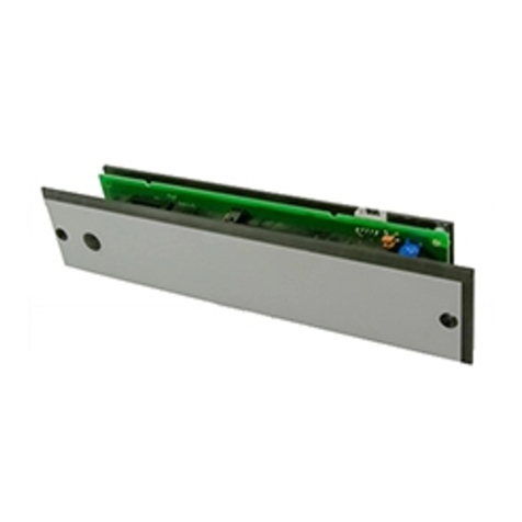
Erone SEFMC2410 User manual

Caratteristiche tecniche
Descrizione
Le fotocellule all’infrarosso codificate ERONE mod.
SEFMC2410 costituiscono un dispositivo di sicurezza
destinato alla protezione di beni e persone in sistemi di
apertura automatica.
Il sistema è composto da una coppia di dispositivi
all'infrarosso TX ed RX ad ottica orientabile, operanti alla
lunghezza d'onda di 850 nm. La portata nominale è di 10
metri, in tutte le condizioni di visibilità ( pioggia, nebbia,
polvere ).
Le ridotte dimensioni d'ingombro ne permettono la
semplicità d'installazione su ogni tipo di struttura.
Sono dotate di un sistema di codifica che permette di far
funzionare contemporaneamente 4 coppie di fotocellule
senza alcun tipo di interferenza.
Installazione
Emissione infrarossi con diodo: GaAlAs
Modulazione digitale: 200 Hz
Lunghezza d’onda di emissione: 850 nm
Alimentazione ( ± 10%): 12 / 24 Vac/dc
Consumo @ 12/24 Vac/dc
- ricevitore: 50 mA
- trasmettitore: 27 mA
Doppio relé con scambi in serie: si
Contatto di uscita: 1 NC / 1 NO
Potere di interruzione corrente continua: 24 W / 48 V
Potere di interruzione corrente alternata: 60 VA / 48 V
Temperatura di funzionamento: -20°C ÷ +55°C
Tempo di intervento < 40 mS
Protezione del contenitore: IP55
Portata nominale in tutte le condizioni: 10 m
Dimensioni (mm): 105 x 33 x 35
1 - Individuare la posizione dei fori di fissaggio utilizzando la guarnizione di
fondo (B). Sulla guarnizione sono presenti due aperture ellittiche che
permettono il fissaggio e la eventuale regolazione successiva nelle 2 direzioni.
2 - Praticare i 2 fori di fissaggio. (diametro del foro: 5 mm);
3 - Posizionare i tasselli (A), in dotazione;
4 - Assemblare la guarnizione (B), la scheda (E) e la guarnizione ad anello
(G);
5 - Far passare i cavi attraverso il foro di ingresso (C);
6 - Fissare la scheda per mezzo delle viti in dotazione (F);
7 - Eseguire i collegamenti elettrici ed alimentare ricevitore e trasmettitore
( Fig. 4)
- alimentazione 12 Vac/dc : Morsetti 0 - 12
- alimentazione 24 Vac/dc : Morsetti 0 - 24.
8 - Connettere l’uscita del relè ( C - NO/NC) al dispositivo di comando.
Sezione di cavo raccomandata:
2
-Cellula trasmittente 2 x 0,6 mm
2
-Cellula ricevente 4 x 0,6 mm .
Messa a punto
La scheda elettronica è fissata alla base per mezzo di 3 viti.
Facendo uso di un cacciavite, avvitare o svitare le viti di regolazione per
variare l’angolo di rotazione del piano scheda. Le 2 viti superiori consentono di
variare la rotazione del piano scheda rispetto all’asse verticale.
La vite inferiore consente di inclinare il piano scheda rispetto all’asse
orizzontale. ( Fig. 2).
Composizione
A - Tasselli di fissaggio
B - Guarnizione
C - Fondo
D - Scheda elettronica
F - Viti di regolazione inclinazione scheda
G - Guarnizione ad anello
H - Vetrino
I - Viti di fissaggio vetrino
L - Tappi di protezione
E - Foro passaggio cavi
Avvertenze
Leggere attentamente le istruzioni prima di effettuare l’installazione! L’uso improprio o il
collegamento errato può pregiudicare il corretto funzionamento del prodotto.
Conformità
Il prodotto risulta conforme a quanto previsto dalle Direttive Europee
89/336/CEE, 89/106/CE , 73/23/CEE,98/37/CE. Risulta inoltre conforme alle
Norme specifiche di prodotto: NFP25-363, IEC 61496-2.
Description
The codified infrared photocells ERONE type
SEFMC2410 are a safety device designed for automatic
closure systems.
The system is composed by a couple of devices, working
on 850 nm wavelenght.
The rated range is 10 meters, in all weather conditions
( rain, fog, dust ).
The reduced dimensions allow easy installations on any
type of structure.
The photocells are equipped with a coding system that
allows the simultaneous operation of 4 couples of devices
without any problem of interference.
Technical specifications
Infrared emission with diode: GaAlAs
Digital modulation: 200 Hz
Wavelength emission: 850 nm
Power supply ( ± 10%): 12 / 24 Vac/dc
Current consumption @12/24 Vac/dc
- receiver: 50 mA
- transmitter: 27 mA
Double contact relay with serial exchange: Yes
Output contacts: 1 NC / 1 NO
Max DC power on relay contacts: 24 W / 48 V
Max AC power on relay contacts: 60 VA / 48 V
Operating temperature: -20°C ÷ +55°C
Reaction time < 40 mS
Housing protection: IP55
Rated range in all conditions: 10 m
Dimensions (mm): 105 x 33 x 35
Warning
Please read carefully this manual before installing the product. Improper use or wrong
connection can compromise the correct operability of the product.
Conformity
This product is complying with all the requirements of the European Directives:
89/336/CEE, 89/106/CE , 73/23/CEE,98/37/CE and the following Regulations:
NFP25-363, IEC 61496-2.
Composition
A - Fixing plugs
B - Sealing gasket
C - Bottom
D - Electronic card
F - Screws for electronic card inclination
G - Ring seal
H - Cover
I - Cover fixing screws
L - Screw caps
E - Wire hole
Installing
1 - Locate the position of the fixing holes using the bottom sealing gasket
(B). On the seal are present 2 elliptic holes that allow the fixing and the next
adjusting along 2 directions.
2 - Drill the 2 fixing holes (Ø 5 mm );
3 - Insert the plugs (A), provided;
4 - Assembly the sealing gasket (B), the electronic card, (E) and the ring
seal (G);
5 - Carry out the wires through the entry hole (C);
6 - Fix the card using the screws (F);
7 - Make the electrical connection and power up the units ( Fig. 4)
- Voltage 12 Vac/dc : Terminals 0 - 12
- Voltage 24 Vac/dc : Terminals 0 - 24.
8 - Connect the relay output ( C - NO/NC) to the driving device.
Recommended wire section:
2
- Transmitting unit 2 x 0,6 mm
2
- Receving unit 4 x 0,6 mm .
Calibration
The electronic card is fixed on the base with 3 screws.
Making use of a screwdriver, screw or unscrew the screws in order to
modify the rotation angle of the card plan .
The upper screws allow to adjust the card plan towards the vertical axis.
The lower screw allow to incline the card plan towards the horizontal axis
(Fig.2).
IT UK
FOTOCELLULE MINI CODIFICATE
CODIFIED MINI PHOTOCELLS

Vmax. Test Point (TP- / TP+)
1,7 V con portata ridotta
with reduced range
3,4 V con portata std
with rated range
TP+
TP-
TX1 RX1
TX2 RX2
TX3 RX3
TX4 RX4
RX TX
0 V
12 Vac/dc
24 Vac/dc NA
NC
C
12 Vac/dc
0 V 24 Vac/dc
LRR LVR
TP+
TP-
J1J2
J1 J2
Connessioni / Connections
J1J2
FT1
J1J2
J1J2
FT2
J1J2
J1J2
FT3
J1J2
J1J2
FT4
J1J2
RX TX
Composizione / Composition
Codifica
Le fotocellule sono CODIFICATE. Ciò significa che ciascun trasmettitore invia
un segnale infrarosso codificato, che può essere riconosciuto esclusivamente
dal corrispondente ricevitore. Sulla scheda elettronica di TX ed RX sono
presenti 2 Jumper ( J1 e J2 ) per l’impostazione della codifica.
Per ciascuna coppia di fotocellule impostare i jumper come indicato in Fig. 3
prima di dare tensione all’apparecchiatura oppure, in caso di variazione,
togliere e ridare alimentazione per far apprendere la combinazione impostata.
E’ possibile installare fino a 4 coppie di fotocellule senza alcun tipo di
interferenza reciproca.
Completamento
1- Fissare il vetrino per mezzo delle viti in dotazione (I);
2 - Inserire i 2 tappini di protezione (L).
Allineamento
Una volta impostata la codifica procedere con l’allineamento. La fotocellula è
allineata quando sul ricevitore il LED VERDE LVR è acceso e il LED ROSSO
LRR è spento. L’allineamento migliore si ottiene quando la tensione max
rilevabile al test point segue quanto riportato in Fig. 7.
Funzionamento a portata ridotta ( < 5m)
Nel caso la distanza tra TX e RX sia inferiore a 5 m rimuovere la lente sul
ricevitore.
NOTA:In questo modo si mantiene la compatibilità alla Normativa IEC61496-2.
Le fotocellule presentano così un cono di emissione di ±5° dell’effettivo angolo
di apertura ed operano con un ridotto valore del segnale IR emesso.
In queste condizioni il valore massimo rilevabile al test point cambia, come
riportato in Fig. 6.
Codifica delle fotocellule mediante jumper
Jumper settings for photocells encoding
Configurazione con fotocellule codificate.
Alimentazione in DC / AC ( 12 / 24 V)
Codified photocells configuration -
Power supply in AC / DC / 12 / 24 V )
Led status
Rosso Verde Descrizione / Description
Red Green
OFF OFF Assenza alimentazione / No supply
ON OFF Presenza ostacolo / Obstacle present
OFF ON Assenza ostacolo / Obstacle absent
La garanzia su questo prodotto è di 24 mesi dalla data di fabbricazione apposta all’interno.
Durante tale periodo, se l’apparecchiatura non funziona correttamente, a causa di un
componente difettoso, essa verrà riparata o sostituita a discrezione del fabbricante.
La garanzia non copre l’integrità del contenitore plastico. La garanzia viene prestata presso
la sede del fabbricante.
2
Garanzia
Encoding
The photocells are CODIFIED. That means that each transmitter sends a
codified infrared beam which can be recognized exclusively by the
corresponding receiver. On the electronic card of RX and TX are located 2
jumpers ( J1 and J2 ) for the encoding setup.
For each couple of photocells set the jumpers as shown on fig. 3 before to
power up the appliance, or, if you need to change the settings, power off
the appliance and power it up again to allow the microprocessor to learn the
new setup.
It’s possible to install up to 4 couples of photocells without any mutual
interference.
Completing
1- Fix the cover with the screws provided (I);
2 - Insert the screw caps (L).
Alignment
Once completed the setup, align the units. The photocell is aligned when
the GREEN Led LVR is ON and the RED Led LRR is OFF. The best
alignment occurs when the voltage measured at the test point is at the max
value ( see Fig. 7).
Short range operating ( < 5m)
When the distance between TX and RX is less than 5 meters, remove the
lens of the receiver.
NOTE: In this way the compliance with the Regulation IEC61496-2 is
mantained. The photocells have, in this case, an emission cone of ±5° and
work with a reduced emitted infrared signal.
In this conditions the max voltage value at the test point changes as shown
on Fig. 6.
The guarantee period of this product is 24 months, beginning from the manufacturer date.
During this period, if the product does not work correctly, due to a defective component,
the product will be repaired or substituted at the discretion of the producer. The guarantee
does not cover the plastic enclosure integrity. After-sale service is supplied at the
producer's factory.
Guarantee
3
45
6
7
IS-FMCERML Rev.0 on 16/06/2006
Elpro Innotek S.p.A.
Via Piave, 23
31020 S.Pietro di Feletto (TV)
Tel: +39-0438-450860 - Fax: +39-0438-455628
THE SMART LIVING
A
B
C
D
E
F
G
H
I
L
