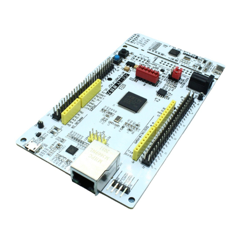
ARTERY AT32-Comm-EV User manual

AT32-Comm-EV User Manual
2022.5.7 1Rev 1.00
AT32-Comm-EV evaluation board
Introduction
The AT32-Comm-EV evaluation board is designed to help users speed up the development of
communication application solutions. It features CAN and RS-485 transceivers, I2C and SPI
connectors. The board can be connected to Artery’s AT-START board or other compatible control
boards through standard ArduinoTM Uno R3 connectors.

AT32-Comm-EV User Manual
2022.5.7 2Rev 1.00
Contents
1Hardware layout and configuration ..................................................................... 5
2Arduino connectors............................................................................................... 7
3How to use AT32-Comm-EV.................................................................................. 9
4Schematics ........................................................................................................... 10
5Revision history................................................................................................... 13

AT32-Comm-EV User Manual
2022.5.7 3Rev 1.00
List of tables
Table 1. ArduinoTM Uno R3 connectors definition................................................................................7
Table 2. Document revision history....................................................................................................13

AT32-Comm-EV User Manual
2022.5.7 4Rev 1.00
List of figures
Figure 1. Top layer layout ....................................................................................................................5
Figure 2. Bottom layer layout...............................................................................................................6
Figure 3. Schematic diagram (power supply, I2C and SPI) ...............................................................10
Figure 4. Schematic diagram (RS-485 and CAN) ............................................................................. 11
Figure 5. Schematic diagram (Arduino UNO R3 extension connectors) ..........................................12

AT32-Comm-EV User Manual
2022.5.7 5Rev 1.00
1 Hardware layout and configuration
The AT32-Comm-EV board is connected to the AT-START board through ArduinoTM connectors. In
this way, the EV board is able to access the CAN, USART, I2C and SPI on embedded AT32 MCU
on AT-START board. This document uses AT-START-F403A board as an example to demonstrate
various functions.
In addition to the embedded AT32 MCU, the AT-START board offers standard ArduinoTM Uno R3
extension connectors to be connected to the AT32-Comm-EV board.
JP1 and JP2 are used to configure whether to turn on 120 Ω termination resistors of the CAN and
RS-485 transceivers, respectively. They are ON by default. The users are allowed to adjust the
resistors according to their needs.
Figure 1and Figure 2 show these features on the AT32-Comm-EV board.
Figure 1. Top layer layout
SPI
connector
RS-485
transceiver
CAN
transceiver
I2C
connector
CAN
connector
RS-485
connector

AT32-Comm-EV User Manual
2022.5.7 6Rev 1.00
Figure 2. Bottom layer layout

AT32-Comm-EV User Manual
2022.5.7 7Rev 1.00
2 Arduino connectors
Table 1. ArduinoTM Uno R3 connectors definition
Connector
Pin
No.
号
Arduino
pin name
AT32F403A
pin name
Function
Description
J4
(power
supply)
1
NC
-
-
-
2
IOREF
-
3.3 V reference voltage
3
RESET
NRST
External reset
-
4
3.3V
-
3.3 V input/output
3.3 V power supply
5
5V
-
5 V input/output
5 V power supply
6
GND
-
Ground
Ground
7
GND
-
Ground
Ground
8
VIN
-
7~12 V input/output
-
J5
(analog
input)
1
A0
PA0
ADC123_IN0
-
2
A1
PA1
ADC123_IN1
USART2_RTS_DE or GPIO
3
A2
PA4
ADC12_IN4
-
4
A3
PB0
ADC12_IN8
-
5
A4
PC1 or PB9
ADC123_IN11 or
I2C1_SDA
-
6
A5
PC0 or PB8
ADC123_IN10 or
I2C1_SCL
-
J2
(logic
input/output
low bytes)
1
D0
PA3
USART2_RX
USART2_RX
2
D1
PA2
USART2_TX
USART2_TX
3
D2
PA10
-
-
4
D3
PB3
TMR2_CH2
-
5
D4
PB5
-
-
6
D5
PB4
TMR3_CH1
-
7
D6
PB10
TMR2_CH3
I2C2_SCL
8
D7
PA8
-
-
J1
(logic
input/output
high bytes)
1
D8
PA9
-
-
2
D9
PC7
TMR3_CH2
-
3
D10
PA15 or PB6
SPI1_NSS or TMR4_CH1
-
4
D11
PA7
TMR3_CH2 or SPI1_MOSI
-
5
D12
PA6
SPI1_MISO
-
6
D13
PA5
SPI1_SCK
-
7
GND
-
Ground
Ground
8
AREF
-
VREF+ input/output
-
9
SDA
PB9
I2C1_SDA
CAN1_TX
10
SCL
PB8
I2C1_SCL
CAN1_RX

AT32-Comm-EV User Manual
2022.5.7 8Rev 1.00
Connector
Pin
No.
号
Arduino
pin name
AT32F403A
pin name
Function
Description
J3
(others)
2
MISO
PB14
SPI2_MISO
SPI2_MISO
1
5V
-
5 V input/output
5 V power supply
4
SCK
PB13
SPI2_SCK
SPI2_SCK
3
MOSI
PB15
SPI2_MOSI
SPI2_MOSI
6
RESET
NRST
External reset
-
5
GND
-
Ground
-
8
CS
PB12
SPI2_CS
SPI2_CS
7
PB11
PB11
-
I2C2_SDA

AT32-Comm-EV User Manual
2022.5.7 9Rev 1.00
3 How to use AT32-Comm-EV
Insert the AT32-Comm-EV board into the Arduino connectors on AT-START board so that two
parts are connected together. After successful connection, supply 5 V and 3.3 V for the combined
board according to the descriptions of Power supply section of the AT-START user manual. Then it
is ready to use the AT32-Comm-EV board, in which the CN1 is used to connect to SPI device, the
CN2 to I2C device, CN3 to RS-485, and CN4 to CAN.
Example codes regarding AT32-Comm-EV board can be found in BSP, including:
CAN example code:
AT32xxx_Firmware_Library_V2.x.x\project\at_start_xxx\examples\can\communication_mode;
RS-485 example code:
AT32xxx_Firmware_Library_V2.x.x\project\at_start_xxx\examples\usart\rs485;
I2C example code:
AT32xxx_Firmware_Library_V2.x.x\project\at_start_xxx\examples\i2c\eeprom;
SPI example code:
AT32xxx_Firmware_Library_V2.x.x\project\at_start_xxx\examples\spi\w25q_flash。
A A
B B
C C
D D
1
1
2
2
3
3
4
4
5
5
Title:
Power & I2C& SPI REV: 1.0
Date: 2022-05-07
Sheet: 1
Drawn By:
Company: Artery Technology
100R
R12
100R
R13
1.8K
R10
1.8K
R11
PB14
PB13
NRST
PB12
PB15
PB11
Reset
To Device
PB10
+3V3
100RR7
100RR5
100RR9
100RR6
100RR8
+5V
GND
GND
E3.3V+3V3
GND EGND
0RR1
EGND EGND EGND EGND EGND
EGND EGND
4.7uF
C5 4.7uF
C4
0.1uF
C2
0.1uF
C3
0.1uF
C6
E3.3V
PB12/SPI2_NSS
PB14/USART3_RTS/SPI2_MISO
PB15/SPI2_MOSI
PB13/USART3_CTS/SPI2_SCK
PB11/USART3_RX/I2C2_SDA
PB10/USART3_TX/I2C2_SCL
SPI
Header 4
CN2
1
1
2
2
3
3
4
4
SMBJ3.3A
D2
EGND
GND
1K
R3
Green
LED1
GND
GND
4.7uF
C1
SMD0603B050TF
F1
E3.3V
EGND
Header 7
CN1
1
1
2
2
3
3
4
4
5
5
6
6
7
7
ME6211C33M5G-N
U1
VIN
1
VSS
2
CE
3NC 4
VOUT 5
ESD5341N-2/TR
D3 D4 D5 D6 D7
D9
ESD5341N-2/TR
D8
SD
I2C
I2C
AT32-Comm-EV User Manual
2020.5.7 10 Rev 1.00
4 Schematics
Figure 3. Schematic diagram (power supply, I2C and SPI)

A A
B B
C C
D D
1
1
2
2
3
3
4
4
5
5
Title:
RS485 & CAN REV: 1.0
Date: 2022-05-07
Sheet: 2
Drawn By:
Company: Artery Technology
GND
KF126-5.0
CN4
1
1
2
2
0.1uFC11
+5V
+5V
+5V
PB9
CAN_L
CAN_H
PB8
GND
+3V3
SP3485EN-L/TR
U2
RO
1RE#
2DE
3DI
4GND 5
A6
B7
VCC 8
PA1
0.1uF
C7
+3V3
PA3
PA2
+3V3
47K
R23
330RR27
0R
R28
120R
R26
120R
R17
KF126-5.0
CN3
1
1
2
2
10K
R15
10K
R20
GND
47K
R14
GND
330RR19
330RR18
330RR16
330RR25
RS485_A
RS485_B
0.1uF
C8
PA2/USART2_TX
PA1/USART2_RTS
PA3/USART2_RX
PB9/CAN_TX
PB8/CAN_RX
RS485
CAN
GND GND
GND GND
SMAJ6.8CA
D11
SMAJ6.8CA
D12
SMAJ6.8CA
D10
SMAJ6.8CA
D15
SMAJ6.8CA
D14
SMAJ6.8CA
D13
TJA1042T/3/1J
U3
TXD
1
GND
2
VCC
3
RXD
4VIO 5
CANL 6
CANH 7
STB 8
JP1
1
1
2
2
JP2
1
1
2
2
(Default ON)
(Default ON)
SD
AT32-Comm-EV User Manual
2020.5.7 11 Rev 1.00
Figure 4. Schematic diagram (RS-485 and CAN)

A A
B B
C C
D D
1
1
2
2
3
3
4
4
5
5
Title:
Arduino UNO R3 connectors REV: 1.0
Date: 2022-05-07
Sheet: 3
Drawn By:
Company: Artery Technology
GND
A0
A1
A2
A3
A4
A5 D0_RX
D1_TX
D2
D3
D4
D5
D6
D7
D8
D9
D10
D11
D12
D13
SDA
SCL
GND
MISO
SCK
NSS
MOSI
+3V3
PB10
PB11
PB15
PB12
PB13
PB14
PA2
PA3
PA1
PB9
PB8
NRST
NRST
GND
+5V
+5V
To MCU
Header 8
J2
11
22
33
44
55
66
77
88
Header 8
J4
1
1
2
2
3
3
4
4
5
5
6
6
7
7
8
8
Header 10
J1
11
22
33
44
55
66
77
88
99
10 10
Header 6
J5
1
2
3
4
5
6
Header 4X2
J3
12
34
56
78
SD
AT32-Comm-EV User Manual
2020.5.7 12 Rev 1.00
Figure 5. Schematic diagram (Arduino UNO R3 extension connectors)

AT32-Comm-EV User Manual
2022.5.7 13 Rev 1.00
5 Revision history
Table 2. Document revision history
Date
Revision
Changes
2022.5.7
1.00
Initial release

AT32-Comm-EV User Manual
2022.5.7 14 Rev 1.00
IMPORTANT NOTICE – PLEASE READ CAREFULLY
Purchasers are solely responsible for the selection and use of ARTERY’s products and services, and ARTERY assumes no liability
whatsoever relating to the choice, selection or use of the ARTERY products and services described herein.
No license, express or implied, to any intellectual property rights is granted under this document. If any part of this document deals with any
third party products or services, it shall not be deemed a license grant by ARTERY for the use of such third party products or services, or any
intellectual property contained therein, or considered as a warranty regarding the use in any manner whatsoever of such third party products
or services or any intellectual property contained therein.
Unless otherwise specified in ARTERY’s terms and conditions of sale, ARTERY provides no warranties, express or implied, regarding the
use and/or sale of ARTERY products, including but not limited to any implied warranties of merchantability, fitness for a particular purpose
(and their equivalents under the laws of any jurisdiction), or infringement of any patent, copyright or other intellectual property right.
Purchasers hereby agrees that ARTERY’s products are not designed or authorized for use in: (A) any application with special requirements
of safety such as life support and active implantable device, or system with functional safety requirements; (B) any air craft application; (C)
any automotive application or environment; (D) any space application or environment, and/or (E) any weapon application. Purchasers’
unauthorized use of them in the aforementioned applications, even if with a written notice, is solely at purchasers’ risk, and is solely
responsible for meeting all legal and regulatory requirement in such use.
Resale of ARTERY products with provisions different from the statements and/or technical features stated in this document shall
immediately void any warranty grant by ARTERY for ARTERY products or services described herein and shall not create or expand in any
manner whatsoever, any liability of ARTERY.
© 2022 Artery Technology -All rights reserved
Table of contents
Other ARTERY Motherboard manuals

ARTERY
ARTERY AT-START-F425 User manual

ARTERY
ARTERY AT-START-F407 User manual

ARTERY
ARTERY AT-SURF-F437 User manual

ARTERY
ARTERY AT32-Video-EV User manual

ARTERY
ARTERY AT-START-F403 User manual

ARTERY
ARTERY AT32F435 Series Specification sheet

ARTERY
ARTERY AT-START-WB415 User manual

ARTERY
ARTERY AT32F4 Series User manual

ARTERY
ARTERY AT32F415 Series User manual