Improper operation can cause serious
injury or death.
Pre-operation
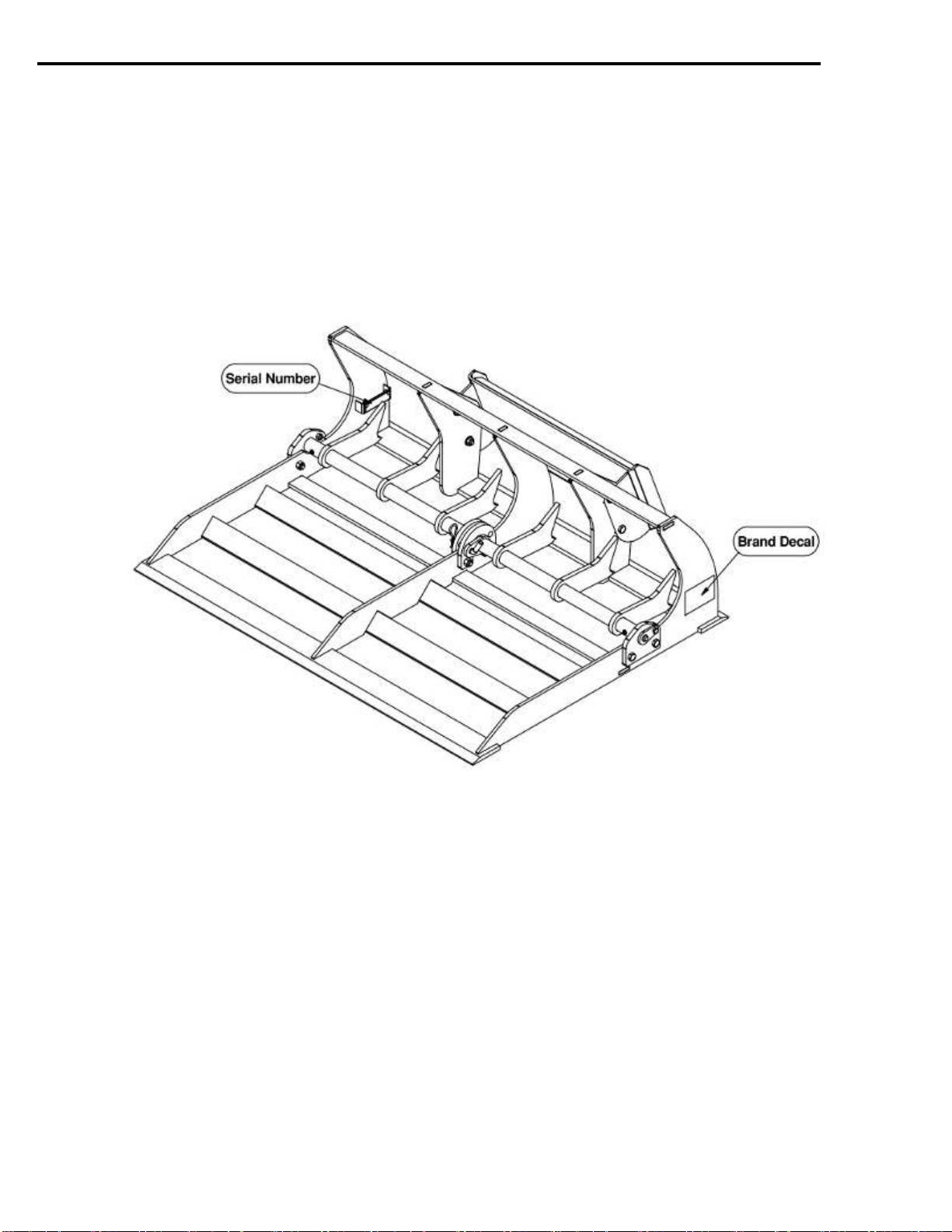
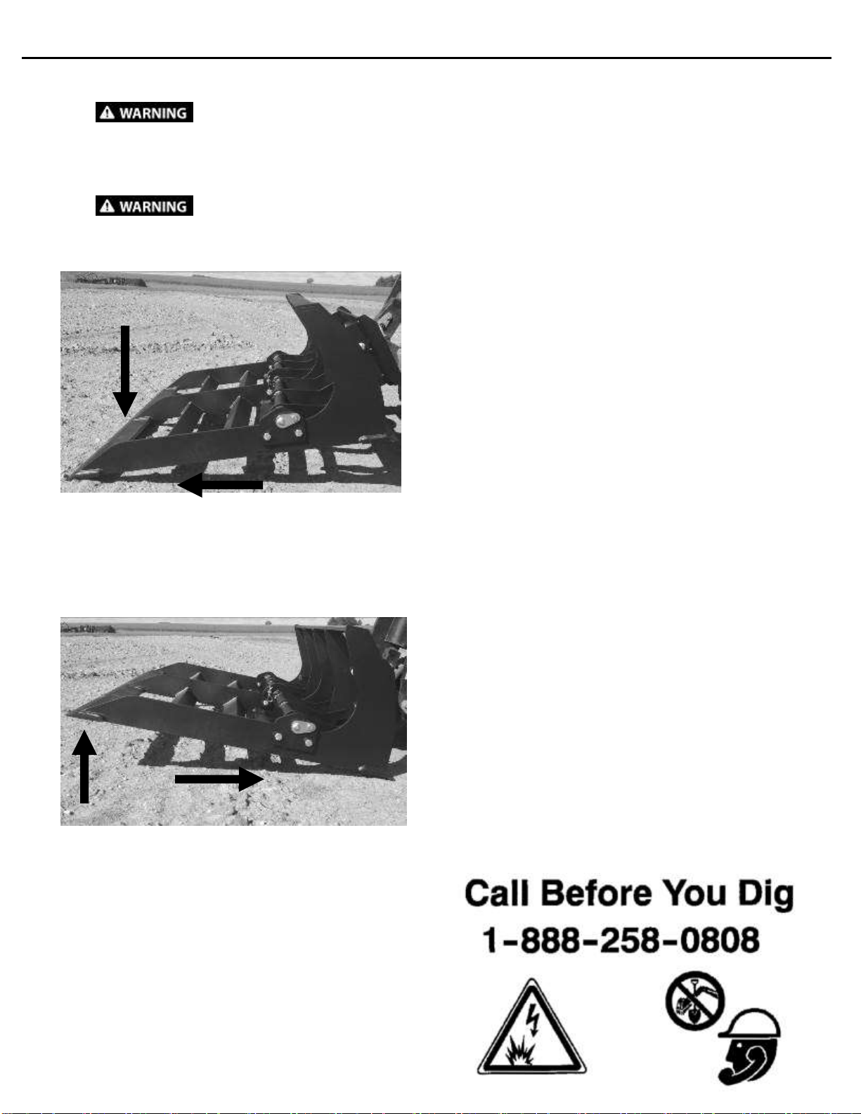
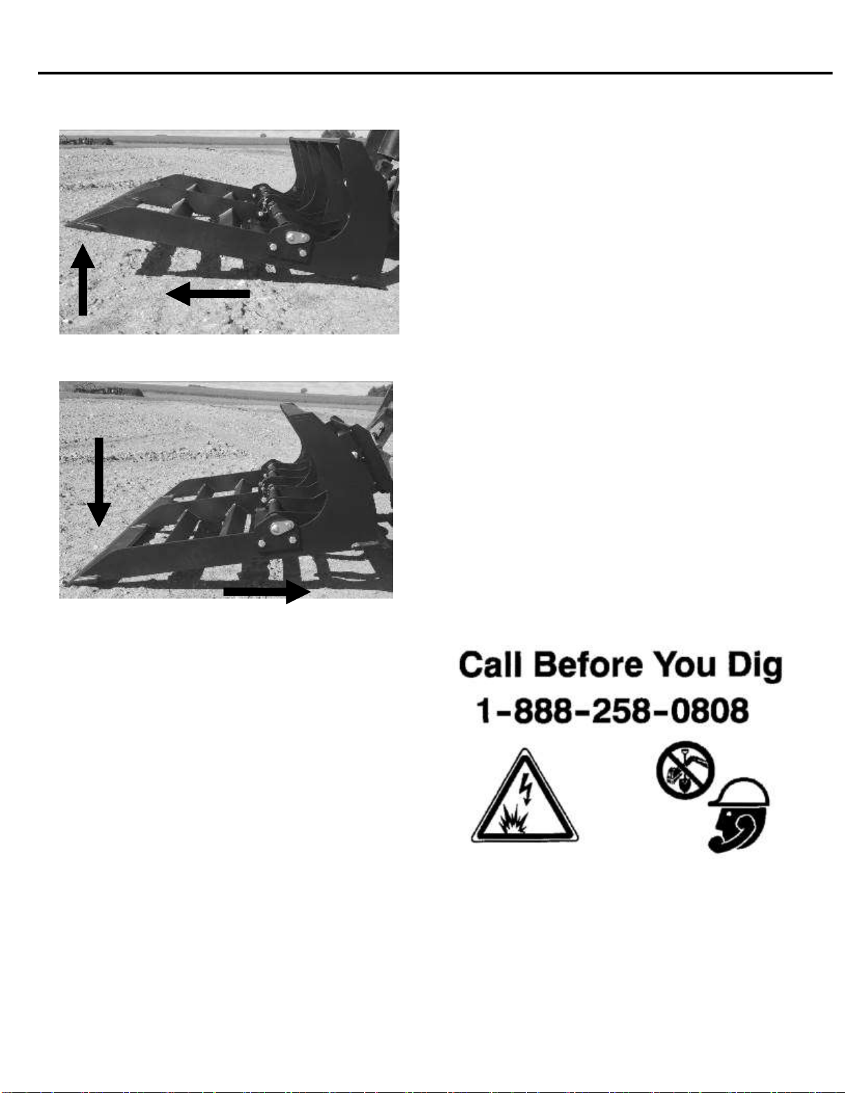
This attachment is designed to be used for levelling
ground and hauling light material. NEVER use this
machine for any other purpose.
Read the operators manual for the “Mini Skid Steer
Loader”or “Mini Track Loader”.NEVER allow
untrained people to operate.
Operating instructions must be given to everyone
before operating this attachment and at least once a
year thereafter in accordance with OSHA regulations.
NEVER exceed the maximum recommended input
power or speed specifications for the attachment.
Over-powering or over-speeding the attachment may
cause personal injury and/or machine damage.
Do not modify equipment or add attachments that are
not approved by Erskine Attachments LLC.
Use adequate safety warning lights and devices as
required by local regulations. Obey all local laws and
regulations regarding machine operation on public
property. Always call before you dig (1-888-258-
0808). When you call, you will be directed to a
location in your state/city for information about buried
lines (electric, telephone, cable TV, water, sewer, gas,
etc.).
Wear Personal Protective Equipment (PPE)
Avoid loose fitting clothing. Clothing caught in moving
parts may lead to serious injury or death.
Flying debris can get in eyes and lead to injury or loss
of eyesight. Wear eye protection that meets ANSI
z87.1 standard.
Prolonged exposure to loud noise can cause hearing
impairment or hearing loss. Wear suitable hearing
protection such as earmuffs or earplugs.
Operation
Check and be sure all operating controls are in neutral
before starting the engine.
NEVER operate near embankments or terrain that is
so steep that rollover could occur.
Always stay in the operator position when using the
attachment.
Before leaving the operators position, lower the
attachment to rest flat on the ground, stop engine, set
park brake.
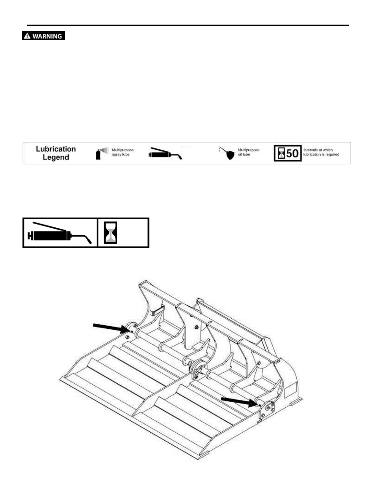
Maintenance
NEVER make adjustments, lubricate, clean, or
perform any service on the machine while it is in
operation.
Make sure the attachment is serviced on a daily
basis. Improper maintenance can cause serious
injury or death in addition to damage to the
attachment and/or your equipment.