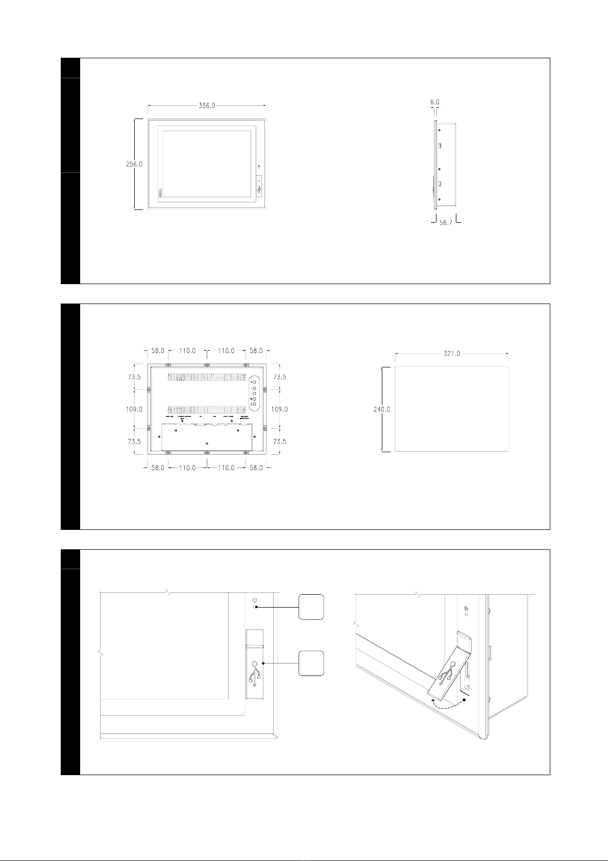
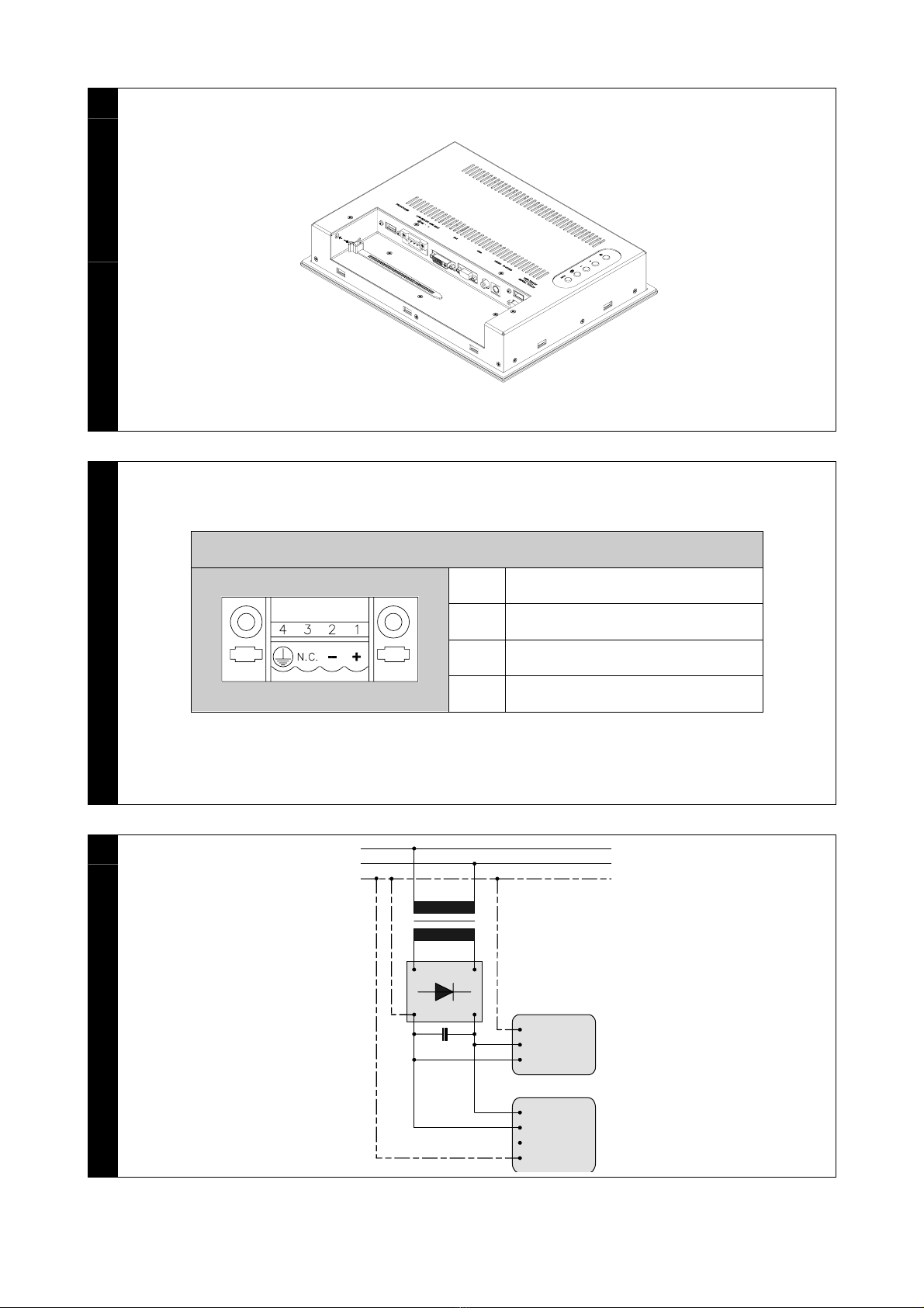
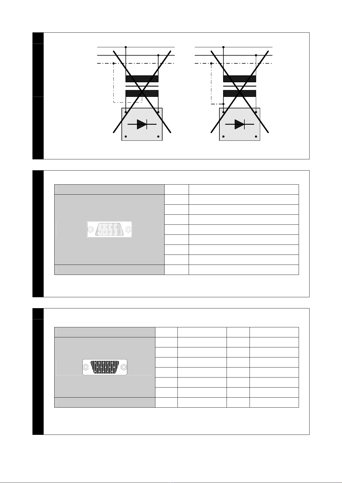
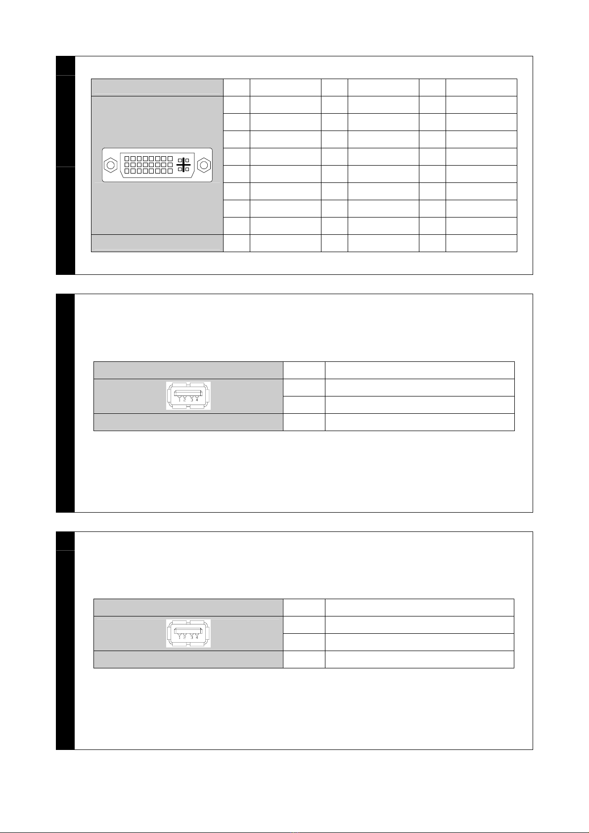
ESA XM7 Series User manual

IT Istruzioni per installazione
EN Installation manual
FR Instructions pour l’installation
DE Installationsanweisung
ES Instrucciones para instalación
CN 安装手册
XM7 SERIES
INDUSTRIAL MONITOR

1
X
M
7
1
2
2
X
M
7
1
2
3
X
M
7
1
2
1
2

4
X
M
7
1
2
5
X
M
7
1
5
6
X
M
7
1
5

7
X
M
7
1
5
1
2
8
X
M
7
1
5
9
X
M
7
1
7

10
X
M
7
1
7
11
X
M
7
1
7
2
1
12
X
M
7
1
7

13
X
M
7
1
9
14
X
M
7
1
9
15
X
M
7
1
9
1
2

16
X
M
7
1
9
17
X
M
7 B C D
H
A E F
G
18
X
M
7 B C D EA

19
X
M
7
20
X
M
7
Power supply 4 pins connectors
1 +24 VDC
2 0 VDC
3 Not Connected
4 Protective ground
21
X
M
7
~
+- 24V
3
+24V
PE
0V
XM
DEVICE
PE
N
L1
4
1
2

22
X
M
7
~
+-
24V
PE
N
L1
~
-
24V
+
PE
N
L1
23
X
M
7
SERIAL TOUCH 1 N.C.
2 TXD OUT
3 RXD IN
4 N.C.
5 Signal GND
6 +5V OUT
7 N.C.
8 +VCC IN
Db 9 female connector 9 N.C.
24
X
M
7
VGA 1 RED 9 N.C.
2 GREEN 10 VGA-DET
3 BLUE 11 ISP-SDA
4 ISP-SCL 12 VGA-COM
5 GND 13 VGA H SYNC
6 RED GND 14 VGA V SYNC
1
6
11
7 GREEN GND 15 VGA CLK
Db 15 female connector 8 BLUE GND

25
X
M
7
DVI-D Single Link 1 TX2- 11 GND 21 N.C.
2 TX2+ 12 N.C. 22 GND
3 GND 13 N.C. 23 TXCLK+
4 N.C. 14 VCC 24 TXCLK-
5 N.C. 15 DVI-DET C1
N.C.
6 DDC CLK 16 HP DETECT C2
N.C.
7 DDC DATA 17 TX0- C3
N.C.
8 N.C. 18 TX0+ C4
N.C.
18
916
17 24
C1 C2
C3 C4
C5
9 TX1- 19 GND C5 GND
Dvi 29 female connector 10 TX1+ 20 N.C.
26
X
M
7
FRONT-USB 1 USBVCC (OUT)
2 USBD-
3 USBD+
4 pin male connector 4 Signal GND
27
X
M
7
USB-TOUCH 1 USBVCC (OUT)
2 USBD-
3 USBD+
4 pin male connector 4 Signal GND

28
X
M
7
VIDEO
1 RCA1
1
22 GND
RCA 2 pin female connector - -
29
X
M
7
S-VIDEO 1 GND Y
2 GND C
3 SY
Minidin 4 pin female connector 4 SC
30
X
M
7
RxD
TxD
GND
3
2
5
TxD
RxD
GND
3
2
6
8
5
+5V
VCC
PC COM SERIAL TOUC
H
D-SUB
9 PIN FEMALE
D-SUB
9 PIN MALE
Max. 15m.

IT_Italiano
AVVERTENZA
IMPORTANTE: leggere
attentamente queste istruzioni
prima della installazione del
prodotto.
Dimensioni e forature
XM712 – Fig. 1 . 2
XM715 – Fig. 5 . 6
XM717 – Fig. 9 . 10
XM719 – Fig. 13 . 14
Vista frontale
XM712 – Fig. 3
XM715 – Fig. 7
XM717 – Fig. 11
XM719 – Fig. 15
1) Porta seriale USB.
2) Led di segnalazione funzionamento.
Legenda:
! Spento - Alimentazione non
presente.
! Acceso GIALLO - Alimentazione
presente ma manca segnale video.
! Acceso VERDE - Funzionamento
regolare.
Vista posteriore
XM7xx – Fig. 17
A) FRONT-USB: Porta per remotare USB
frontale.
B) Alimentazione.
C) DVI-D (single link): Porta DVI per il
collegamento della scheda video del
PC.
D) VGA: Porta CRT per il collegamento
della scheda video del PC.
E) S-VIDEO: Porta S-Video per il
collegamento della scheda video del
PC.
F) SERIAL TOUCH: Porta RS232 per
Touch Screen.
G) USB-TOUCH: Porta USB per Touch
Screen.
H) VIDEO: Porta RCA per il collegamento
della scheda video del PC.
ATTENZIONE: Si consiglia di utilizzare
una sola porta per collegare il touch
screen (Serial-Touch oppure Usb-
Touch).
IMPORTANTE: Per il collegamento
mediante Serial Touch utilizzare
esclusivamente un cavo come da
schema allegato (Fig. 30)
L’utilizzo di qualunque altro tipo di
cavo può danneggiare
l’apparecchiatura.
Tastierino OSD
XM7xx – Fig. 18
A) Consente la regolazione automatica del
monitor.
B) Consente di richiamare a video il menù
/ Confermare le scelte.
C) Consente di spostarsi nel menù a video
/ Diminuire valore.
D) Consente di spostarsi nel menù a video
/ Aumentare valore.
E) Accensione Monitor.
Installazione XM
XM712 – Fig. 4
XM715 – Fig. 8
XM717 – Fig. 12
XM719 – Fig. 16
Per ancorare i cavi inserire le fascette
in dotazione negli appositi fori (Fig. 19).
Alimentazione
Fig. 20 - Significato dei pin del
connettore di alimentazione.
Fig. 21 - Collegamento consigliato.
Fig. 22 - ATTENZIONE: questa due
configurazioni danneggiano
gravemente il XM.
IMPORTANTE: La massa dei
dispositivi collegati alle porte di
comunicazione seriali e/o parallele
deve essere tassativamente allo
stesso potenziale dello 0V di
alimentazione del XM. La
circolazione di una corrente tra lo 0V

di alimentazione e la massa delle
porte di comunicazione potrebbe
causare il danneggiamento di alcuni
componenti del XM o dei dispositivi
ad esso collegati.
Temperatura di esercizio
0 / +50°C
Impostazione parametri di
setup
a. Eseguire tutti i collegamento
mantenendo il monitor spento.
b. Avviare il PC.
c. Avviare il monitor.
d. Caricare i driver del touch screen.
e. Assicurasi di avere impostato le
seguenti risoluzioni:
! XM712 – 800x600
! XM715 – 1024x768
! XM717 – 1280x1024
! XM719 – 1280x1024
Porte di comunicazione
Fig. 23 . 24 . 25 . 26 . 27 . 28 . 29
Pulizia della superficie
Per la pulizia del XM si consiglia di
utilizzare Alcool Etilico Denaturato.
Certificazini
Tutti i prodotti descritti in questo
manuale sono conformi ai seguenti
standard:
compatibilità elettromagnetica (EMC):
! emissioni EN 61000-6-3 (2007)
! immunità EN 61000-6-2 (2005)
e perciò rispondono a:
Council Directive
EMC 2004/108/EC
EN_English
WARNING
IMPORTANT: Please read
carefully these instructions
before mounting the product.
Dimensions and holes
XM712 – Fig. 1 . 2
XM715 – Fig. 5 . 6
XM717 – Fig. 9 . 10
XM719 – Fig. 13 . 14
Front view
XM712 – Fig. 3
XM715 – Fig. 7
XM717 – Fig. 11
XM719 – Fig. 15
1) Universal Serial Bus port.
2) LED indicating functional state.
Legend:
! Off - No power source.
! YELLOW On - Power present but no
video signal.
! GREEN On - Functioning correctly.
Rear view
XM7xx – Fig. 17
A) FRONT-USB: Port to remote front USB.
B) Power supply.
C) DVI-D (single link): DVI port for
connecting with PC graphics board.
D) VGA: CRT port for connecting with PC
graphics board.
E) S-VIDEO: S-Video port for connecting
with PC graphics board.
F) SERIAL TOUCH: RS232 port for Touch
Screen.
G) USB-TOUCH: USB port for Touch
Screen.
H) VIDEO: RCA port for connecting with
PC graphics board.
WARNING: It is advisable to use only
one port to connect the touch screen
(Serial Touch or USB-Touch).

IMPORTANT: For connection by
means of Serial-Touch, use only a
cable as shown in the attached
layout (Fig. 30).
Use of any other type of cable may
damage the equipment.
OSD keypad
XM7xx – Fig. 18
A) Allows the automatic regulation of the
monitor.
B) Allows you to display the menu /
Confirm selections.
C) Allows you to move within the on-
screen menu / To decrease the value.
D) Allows you to move within the on-
screen menu / To increase the value.
E) Turning on the Monitor.
Installing the XM
XM712 – Fig. 4
XM715 – Fig. 8
XM717 – Fig. 12
XM719 – Fig. 16
To anchor the cables, insert the
provided bands in the appropriate holes
(Fig. 19).
Power supply
Fig. 20 - Power connector pin-out.
Fig. 21 - Recommended power
connection.
Fig. 22 - Warning: These two
configuration will seriously damage
components.
IMPORTANT: The earth of the
devices connected to the serial
and/or parallel communication ports
MUST have the same potential as the
0V supply of the XM. The circulation
of current between the 0V supply
and the earth of the communication
ports could cause damage to certain
components of the XM or of the
devices connected to it.
Working temperature
0 / +50°C
Entering set-up parameters
a. Carry out all connections with the
monitor off.
b. Start up PC.
c. Start-up the monitor.
d. Load touch screen drivers.
e. Check that XM has been set with
resolution of:
! XM712 – 800x600
! XM715 – 1024x768
! XM717 – 1280x1024
! XM719 – 1280x1024
Communication ports
Fig. 23 . 24 . 25 . 26 . 27 . 28 . 29
Cleaning
For cleaning the XM we recommend
Denaturalised Ethyl Alcohol.
Certifications
All the products described in this
manual comply with the following
standards:
electromagnetic compatibility (EMC):
! emissions EN 61000-6-3 (2007)
! immunity EN 61000-6-2 (2005)
and thus are in line with:
Council Directive
EMC 2004/108/EC

FR_Français
AVERTISSEMENT
IMPORTANT : lire attentivement
ces instructions avant
l’installation du produit.
Dimensions et perçage
XM712 – Figure . 1 . 2
XM715 – Figure . 5 . 6
XM717 – Figure . 9 . 10
XM719 – Figure . 13 . 14
Vue frontale
XM712 – Figure . 3
XM715 – Figure . 7
XM717 – Figure . 11
XM719 – Figure . 15
1) Port Universal Serial Bus.
2) Led de signalisation de fonctionnement.
Légende :
! Eteint - Absence d'alimentation.
! JAUNE allumé - Présence
d'alimentation mais absence de
signal vidéo.
! VERT allumé - Fonctionnement
régulier.
Vue postérieure
XM717 – Figure . 17
A) FRONT-USB: Port pour mettre à
distance USB frontal.
B) Alimentation.
C) DVI-D (single link): Port DVI pour le
raccordement de la carte vidéo du PC.
D) VGA: Port CRT pour le raccordement
de la carte vidéo du PC.
E) S-VIDEO: Port S-Video pour le
raccordement de la carte vidéo du PC.
F) SERIAL TOUCH: Port RS232 pour
Ecran Tactile.
G) USB-TOUCH: Port USB pour Ecran
Tactile.
H) VIDEO: Port RCA pour le raccordement
de la carte vidéo du PC.
ATTENTION : Nous conseillons
d'utiliser un seul port pour brancher
l'écran tactile (Serial Touch ou bien
Usb-Touch).
IMPORTANT : Pour le raccordement
au moyen du Serial Touch utiliser
exclusivement un câble comme
illustré dans le schéma ci-joint
(Figure. 30).
L'utilisation de tout autre type de
câble peut endommager
l'appareillage.
Claveir OSD
XM7xx – Fig. 18
A) Permet le réglage automatique de
l'écran.
B) Permet de rappeler à l'écran le menu /
Confirmer les choix.
C) Permet de se déplacer dans le menu à
l'écran / Diminuer la valeur.
D) Permet de se déplacer dans le menu à
l'écran / Augmenter la valeur.
E) Allumage Ecran.
Installation du XM
XM712 – Figure . 4
XM715 – Figure . 8
XM717 – Figure . 12
XM719 – Figure . 16
Pour fixer les câbles insérer les colliers
de serrage fournis en équipement dans
les trous spécifiques (Figure. 19).
Alimentation
Figure . 20- signification des pins du
connecteur d’alimentation.
Figure . 21 - connexion conseillée.
Figure . 22 - Attention : Ces deux
configurations peuvent endommager
certains composants.
IMPORTANT : La masse des
dispositifs connectés aux ports de
communication parallèles ou sériels
doit formellement être au même
potentiel qu’il 0V d’alimentation du

XM. La circulation d’un courant entre
il 0V d’alimentation et la masse des
ports de communication pouvait
causer des dommages aux
composants du XM ou des
dispositifs connectés.
Température d’exercice
0 / +50°C
Chargement des paramètres de
setup
a. Exécuter tous les raccordements en
maintenant l'écran éteint.
b. Lancer le PC.
c. Allumer l'écran.
d. Charger les driver de l'écran tactile.
e. S'assurer d'avoir réglé le XM avec
résolution :
! XM712 – 800x600
! XM715 – 1024x768
! XM717 – 1280x1024
! XM719 – 1280x1024
Portes de comunication
Figure . 23 . 24 . 25 . 26 . 27 . 28 . 29
Nettoyage
Pour nettoyer le XM est conseillé
d’utiliser de l’Alcool Éthylique
Dénaturé.
Certifications
Tous les produits décrits dans ce
manuel sont conformes aux standards
suivants :
compatibilité electromagnétique (EMC) :
! émissions EN 61000-6-3 (2007)
! immunité EN 61000-6-2 (2005)
et ils répondent pour cela aux :
Council Directive
EMC 2004/108/EC
DE_Deutsch
HINWEIS
WICHTIG: lesen
Sie die Hinweise sorgfältig
durch bevor Sie Installationen
durchführen.
Maße und Ausschnitt
XM712 – Abbildung . 1 . 2
XM715 – Abbildung . 5 . 6
XM717 – Abbildung . 9 . 10
XM719 – Abbildung . 13 . 14
Vorderansicht
XM712 – Abbildung . 3
XM715 – Abbildung . 7
XM717 – Abbildung . 11
XM719 – Abbildung . 15
1) Universellen seriellen Bus Port.
2) LED, die den Funktionierungsstatus
angibt.
Zeichenerklärung:
! Abgeschaltet - Keine
Stromversorgung.
! GELB eingeschaltet -
Stromversorgung anwesend aber
kein Videosignal.
! GRÜN eingeschaltet - Funktioniert
richtig.
Rückansicht
XM7xx – Abbildung . 17
A) FRONT-USB: Remote – Schnittstelle
Frontal - USB.
B) Versorgung.
C) DVI-D (single link): DVI-Schnittstelle für
den Anschluss mit dem Grafikboard.
D) VGA: CRT-Schnittstelle für den
Anschluss mit dem Grafikboard.
E) S-VIDEO: S-Video -Schnittstelle für den
Anschluss mit dem Grafikboard.
F) SERIAL TOUCH: RS232 - Schnittstelle
für Touch Screen.
G) USB-TOUCH: USB - Schnittstelle für
Touch Screen.
H) VIDEO: RCA-Schnittstelle für den
Anschluss mit dem Grafikboard.

ACHTUNG: Es ist ratsam, für die
Verbindung des Touch Screens nur
eine Schnittstelle zu verwenden (Serial-
Touch oder auch USB-Touch).
WICHTIG: Für eine Serial Touch –
Verbindung ausschließlich die im
Schaltschema angegeben Kabel
verwenden (Abbildung . 30).
Die Verwendung einer anderen
Kabelart kann das Gerät
beschädigen.
OSD Tastatur
XM7xx – Abbildung . 18
A) Ermöglicht die automatische Regelung
des Monitors.
B) Gestattet die Anzeige des Menüs / Die
Bestätigung der Auswahl.
C)
Gestattet Bewegung innerhalb des
angezeigten Menüs / Wert verringern
.
D)
Gestattet Bewegung innerhalb des
angezeigten Menüs / Wert erhöhen
.
E) Einschalten des Monitors.
XM-Installation
XM712 – Abbildung . 4
XM715 – Abbildung . 8
XM717 – Abbildung . 12
XM719 – Abbildung . 16
Zum Befestigen der Kabel die
beigefügten Schellen in die
entsprechenden Bohrungen einführen
(Abbildung . 19).
Spannungsversorgung
Abbildung . 20 - Anschluß des
Versorgungssteckers.
Abbildung . 21 - Empfohlene
Verdrahtung.
Abbildung . 22 - Warnung: Diese
beiden Anschlussarten führen zu
Schäden am XM Gerät.
WICHTIG: Die Erde der Parallelen und/order
Seriellen Datenleitung müssen das gleiche
Potential haben wie die Erde der
Spannungsversorgung vom Bediengerät.
Eine nicht korrekte Erdung der
Spannungsversorgung und der
Datenleitungen können schwere Schäden an
den Bediengeräten sowie an den
angeschlossene Komponenten hervor rufen.
Betriebstemperatur
0 / +50°C
Eingabe der
Einrichtungsparameter
a. Alle Anschlüsse bei ausgeschaltetem
Monitor ausführen.
b. PC starten.
c. Den Monitor einschalten.
d. Laden Sie die Touch-Screen-Treiber.
e. Kontrollieren Sie, dass die XM –
Auflösung:
! XM712 – 800x600
! XM715 – 1024x768
! XM717 – 1280x1024
! XM719 – 1280x1024
Schnittstellen-Anschlüsse
Abbildung
. 23 . 24 . 25 . 26 . 27 . 28 . 29
Reinigung der Touch-
Oberfläche
Für die Reinigung der Touch
Oberfläche wird die Verwendung von
Ethylalkohol empfohlen.
Zertifizierungen
Alle im vorliegenden Handbuch
beschriebenen Produkte sind konform
mit den folgenden Standards
elektromagnetische Kompatibilität
(EMC):
!
Emissionen EN 61000-6-3 (2007)
!
Störimmunität EN 61000-6-2 (2005)
und entsprechen daher den:
Council Directive
EMC 2004/108/EC

ES_Español
ADVERTENCIA
IMPORTANTE: leer estas
instrucciones con cuidado
antes de la instalación
producto.
Dimensiones y perforaciones
XM712 – Fig. 1 . 2
XM715 – Fig. 5 . 6
XM717 – Fig. 9 . 10
XM719 – Fig. 13 . 14
Vista frontal
XM712 – Fig. 3
XM715 – Fig. 7
XM717 – Fig. 11
XM719 – Fig. 15
1) Puerto Bus de Serie Universal.
2) Led de señalización de funcionamiento.
Leyenda:
! Apagado - Alimentación ausente.
! Encendido AMARILLO -
Alimentación presente pero falta
señal vídeo.
! Encendido VERDE -
Funcionamiento regular.
Vista posterior
XM7xx – Fig. 17
A) FRONT-USB: Puerto para gestión
remota USB frontal.
B) Alimentación.
C) DVI-D (single link): Puerto DVI para la
conexión de la tarjeta vídeo del PC.
D) VGA: Puerto CRT para la conexión de
la tarjeta vídeo del PC.
E) S-VIDEO: Puerto S-Video para la
conexión de la tarjeta vídeo del PC.
F) SERIAL TOUCH: Puerto RS232 para
Pantalla Táctil.
G) USB-TOUCH: Puerta USB para
Pantalla Táctil.
H) VIDEO: Puerto RCA para la conexión
de la tarjeta vídeo del PC.
ATENCIÓN: Se aconseja utilizar un
solo puerto para conectar la pantalla
táctil (Serial Touch o Usb-Touch).
IMPORTANTE: Para la conexión
mediante Serial Touch utilizar
exclusivamente un cable como en el
esquema adjunto (Fig. 30).
El uso de cualquier otro tipo de
cable puede dañar el equipo.
Teclado OSD
XM7xx – Fig. 18
A) Permite la regulación automática del
monitor.
B) Permite visualizar el menú / Confirmar
lo elegido.
C)
Permite desplazarse por el menú vídeo /
Disminuir valor
.
D)
Permite desplazarse por el menú vídeo /
Aumentar valor
.
E) Encendido Monitor.
Instalación del XM
XM712 – Fig. 4
XM715 – Fig. 8
XM717 – Fig. 12
XM719 – Fig. 16
Para amarrar los cables introducir las
fajas en dotación en los orificios
específicos (Fig. 19).
Alimentación
Fig. 20 - Significado de los pines de el
conector de alimentación.
Fig. 21 - Conexión recomendada.
Fig. 22 - Atencion: Las dos
configuraciones de arriba dañan
gravemente el XM.
ATENCION: La masa de los
dispositivos conectados en los
puertos de comunicación serie y/o
paralelo tiene que estar conectada
imprescindiblemente al mismo
potencial del 0V de alimentación del
XM. La circulación de una corriente
entre el 0V de alimentación y la masa

de los puertos de comunicación
podría causar daños a algunos
componentes del XM o bien a
algunos dispositivos conectados.
Temperatura de servicio
0 / +50°C
Definición parámetros de
instalación
a. Hacer todas las conexiones
manteniendo el monitor apagado.
b. Poner en marcha el PC.
c. Inicializar el monitor.
d. Cargar los drivers del touch screen.
e. Asegurarse de que se haya definido el
XM con resolución de:
! XM712 – 800x600
! XM715 – 1024x768
! XM717 – 1280x1024
! XM719 – 1280x1024
Puertos de comunicación
Fig. 23 . 24 . 25 . 26 . 27 . 28 . 29
Como limpiar el XM
Para limpiar el XM se aconseja utilizar
Alcohol Etílico Desnaturalizado.
Certificaciones
Todos los productos descritos en este
manual están conformes con los
siguientes estándares:
compatibilidad electromagnética
(EMC):
! emisiones EN 61000-6-4 (2007)
! inmunidad EN 61000-6-2 (2005)
y por lo tanto se atienen a las:
Council Directive
EMC 2004/108/EC
CN_中文
警告
重要:安装产品之前请仔细阅读本
说明书.
尺寸和孔
XM712–图. 1 . 2
XM715–图. 5 . 6
XM717–图. 9 . 10
XM719–图. 13 . 14
正视图
XM712–图. 3
XM715–图. 7
XM717–图. 11
XM719–图. 15
1) 通用串行总线端口
2) LED(发光二极管) 显示功能状态
图例:
! 灭–无电源
! 黄色亮 - 电源存在,但没有视频信号
! 绿色亮 - 正常工作
后视图
XM7xx–图. 17
A) FRONT-USB:前置远程 USB端口
B) 电源
C) DVI- D (单个):DVI
端口与PC图形卡连接
D) VGA:CRT 端口与PC图形卡连接
E) S-VIDEO:S-Video 端口与PC图形卡连接
F) SERIAL TOUCH:触摸屏的RS232 端口
G) USB-TOUCH:触摸屏的USB 端口
H) VIDEO:RCA 端口与PC图形卡连接
警告:只使用一个端口与触摸屏连接是明
智的选择 (Serial Touch 或者 USB-
Touch).

ESA elettronica S.p.A.
Via Padre Masciadri, 4/A
I – 22066 Mariano Comense (CO)
Tel. ++39-031757400 Fax ++39-031751777
Rev. 0 Date: 02/03/2011 29015.609.652
重要: 用Serial
Touch方式连接时,仅仅使用设计图所示
的电缆(图.30).
使用其它类型的电缆有可能会损坏设备.
OSD 键区
XM7xx–图. 18
A) 允许显示器的自动调节
B) 允许你显示菜单 / 确认选择
C) 允许你在屏幕上移动菜单/减小数值
D) 允许你在屏幕上移动菜单/增加数值
E) 开启监视器
安装 XM
XM712–图. 4
XM715–图. 8
XM717–图. 12
XM719–图. 16
为了锚定电缆,在相应的孔中插入所提供
的带子 (图. 19).
电源
图. 20 - 电源连接器 pin-out
图. 21 - 推荐的电源连接器
图. 22 - 警告:
这两种配置将严重损害的部件
重要:
设备的地线和串行/并行通讯端口的连接
必须XM的0V(伏特)供应具有相同的电
压。在0V (伏特)
供应和通讯端口的地线之间的电流循环
会损坏XM或与之相连的设备的一些零部
件.
工作温度
0 / +50°C
输入 set-up(设置) 参数
a. 监视器关闭时执行所有的连接
b. 开启PC
c. 开启监视器
d. 加载触摸屏驱动程序
e. 检查XM设定如下的分辨率:
! XM712–800x600
! XM715–1024x768
! XM717–1280x1024
! XM719–1280x1024
通讯端口
图. 23 . 24 . 25 . 26 . 27 . 28 .
29
清洁
建议使用普通变性酒精清洁 XM
认证
手册中的所有产品均通过如下标准:
电磁适应性(EMC):
! 散发EN 61000-6-3 (2007)
! 免疫性EN 61000-6-2 (2005)
因为也符合:
理事会指令EMC 2004/108/EC
This manual suits for next models
4
Table of contents
Other ESA Industrial Monitor manuals
Popular Industrial Monitor manuals by other brands

Delta Electronics
Delta Electronics Terminal Panels Series TP02G-AS1 instruction sheet

Nexcom
Nexcom APPD 1200T user manual

Total Controls
Total Controls QuickPanel jr. QPKSxDN0000 Series installation instructions

VarTech Systems
VarTech Systems VT201CHC user guide

Governors America
Governors America EEG6500 manual

Contemporary Research
Contemporary Research FT1-3 product manual