2.2 STANDARD FEATURES
The presence of options on request could nullify or modify the operating of standard features.
Code Description
A1a Minimum and maximum dP alarms on same relay (K2)
Minimum and maximum dP alarms act on the same relay. The display will specify the type of alarm.
A2a Relay Voltage ON (K1)
If the device is supplied, relay K1 is activated and the terminal board contact is closed. In case of power failure, this
contact is open.
AL1 Alarm relay contacts open
The relay contacts signaling the presence of alarm are open if there is no supply or in presence of alarm condition. With
power supply on and in the absence of an alarm, the contact is closed.
Relay contacts: 42 VAC - 5 A Max / 42VDC - 3A Max
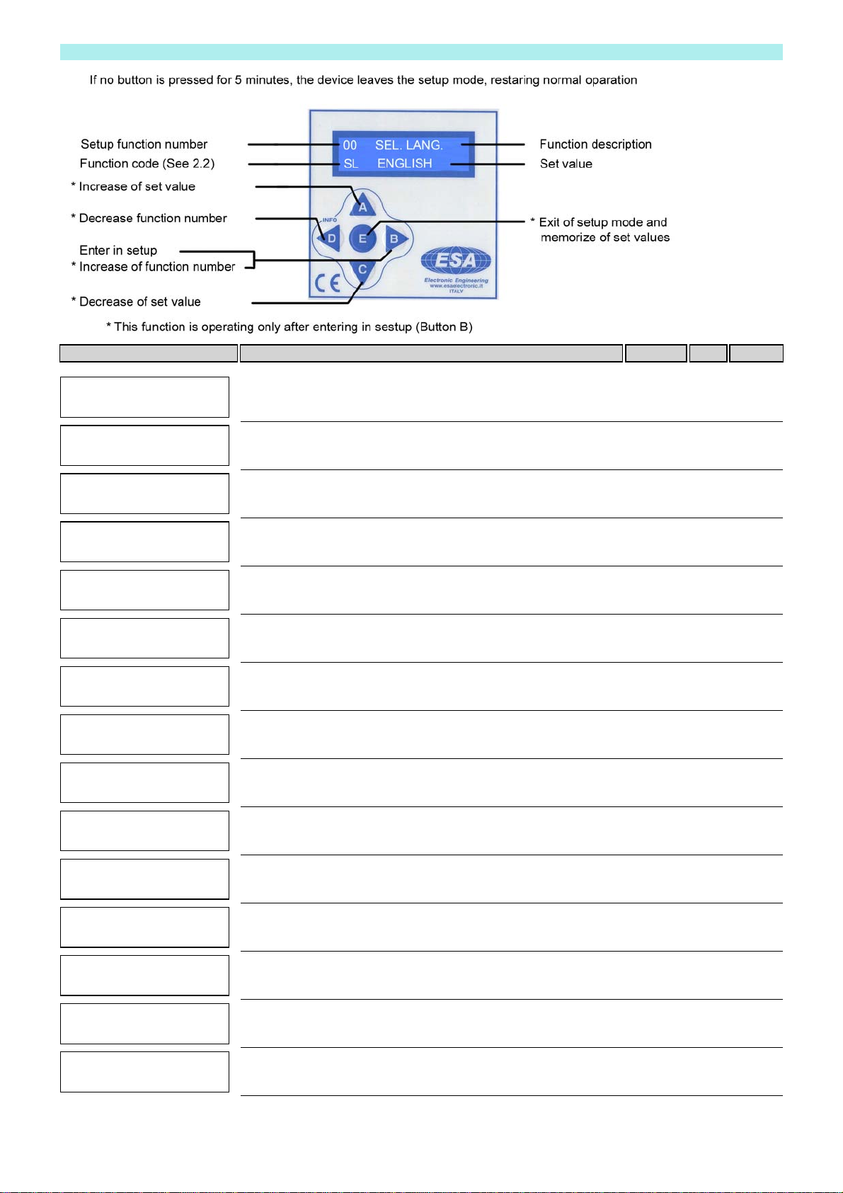
B10 Manual activation of every single output from keyboard
By keyboard, it is possible to activate manually and individually every single output for an operation test.
Press key A to select the desired output to be activated. Press key C to activate the output.
The output is holded active for all the time that key C is pressed. It allows to measure the output voltage by using a
tester.
In case of anomalous operating, do this test with electrovalves disconnected.
B1b Select Number of outputs
The selection of the number of outputs to be control led is connected by keyboard in SET MODE. If you set 0 or AUTO
in this function the sequencer will automatically select the connected loads by skipping the non connected ones.
Minimum load 5W ÷ 12 W depending on the output voltage. If the load is below of the minimum, the autoselection does
not work correctly, set the number of outputs in set up.
B2x Activation time from 0.05 to 5.00 sec.
B3c Interval time between ev. during post-cleaning
Interval time between two activations settable by keyboard when post-cleaning cycles are active and during the forced
cycles of option C2x if available.
The selection range is the same as the inteval time in standard operation mode (B3x).
B3x Interval time from 1 to 999 sec.
If the pulse time is lower than 1 sec. it is possible to set any interval time value in the range indicated.
If the activation time is higher than 1 sec. the minimum settable interval time is:
Minumum interval time = 5 times pulse time (B2x)
B8b Short-circuit protection of every single output
In case of short-circuit, the corresponding output is automatically skipped. Relay K2 will signal the alarm condition and
display will show the alarm situation code E1 (See the alarm description).
Press key E to reset the alarm.
C1 Digital differential pressure control (STOP at cycle end)
In automatic running mode (C4a), the cleaning cycle is activated and deactivated according to the dP readout.
C1a Set the cleaning STOP threshold: if dP is below this threshold, the cleaning cycle stops and the display shows
'CYCLE STOP FOR LOW dP' or the letter 'P' according to the model. The cleaning cycle stops at the end of the cycle.
C1b Set the cleaning START threshold: if dP is above this threshold, the cleaning cycle is activated.
C13_10 dP full range 10.00 kPa = 100.0 mbar = 1012 mmH2O.
Maximum differential pressure value measurable by the device 10.00 kPa = 100.0 mbar = 1012 mmH2O.
With dP reading over 10 kPa the display shows 'E' instead of the numeric value of dP.
C4 Cleaning cycle
If all the requirements for the start-up of the cleaning cycle are fulfilled when supply is powered on (e.g. fan on, external
consents C6 or D5, dP readout above the start threshold), the sequencer will automatically activate the EV outputs
sequencially according to the times set by keyboard.
C4a Automatic operation mode
By keyboard in Setup it is possible to select the operation mode. In automatic mode, the controls of the fan, the dP, C6
and D5 are active and the activation of the cleaning cycle will depend on such functions.
C4b Manual operation mode
By keyboard in Setup it is possible to select the operation mode. In manual mode, the control of the fan, the dP, C6 and
D5 are not active.