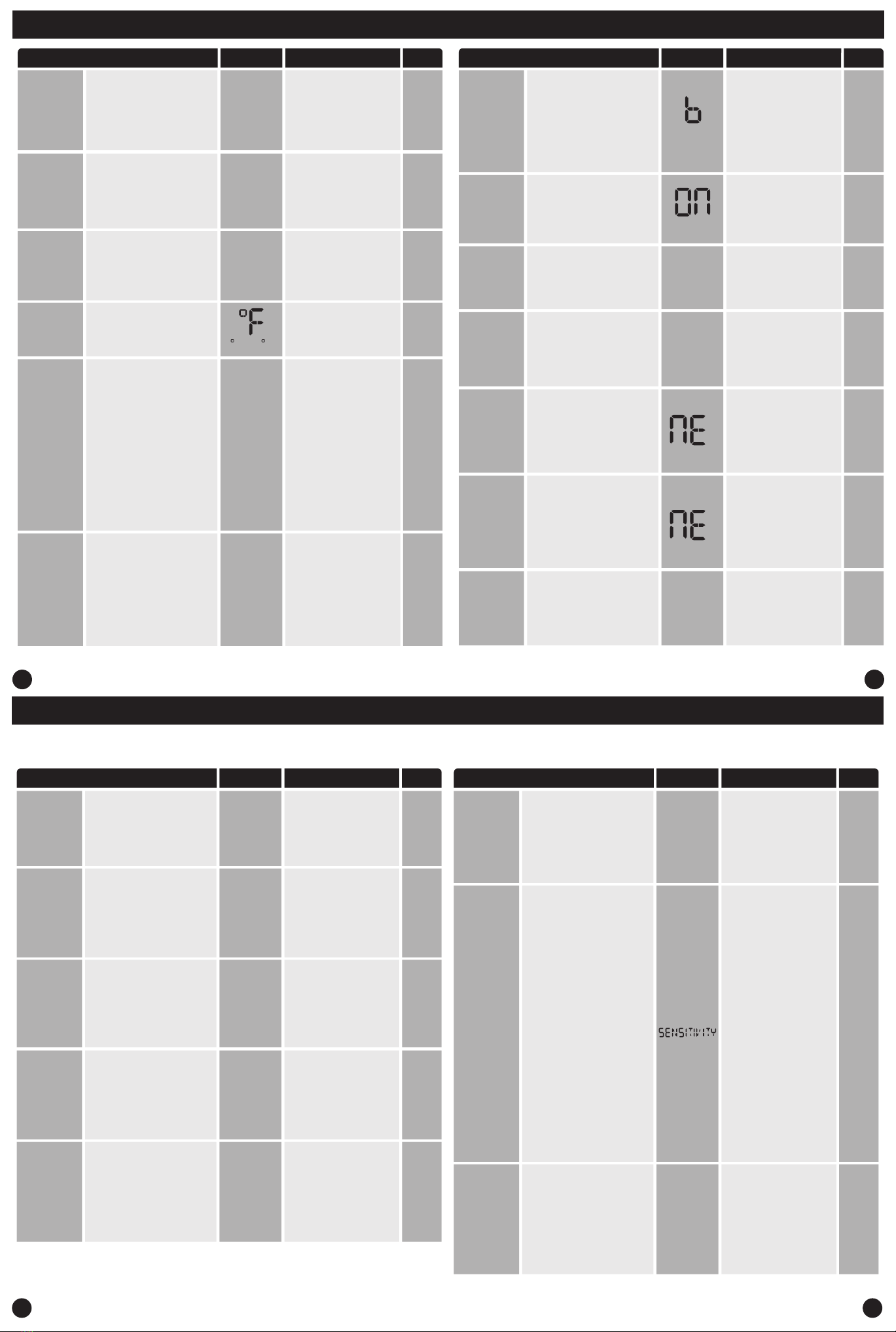
Technician Setup
13
Technician Setup
14
15
Medium
Speed Fan
Terminal
Designation
Tech Setup Steps Adjustment Options Default
LCD Will Show
Fan Speeds
Select number of fan stages you
would like the thermostat to
operate.
1 = 1 Speed: On, Auto
2 = 2 Speed: Low (On L), High
(On H), Auto
3 = 3 Speed: Low (On L), Med
(On M), High (On H), Auto
The display light can be
congured to stay on
permanently or only when a key
is pressed.
NOTE: HARDWIRE ONLY. Keeping
the display light continually“ON”
will greatly reduce battery life.
OF = OFF congures the
display light to come on when
the light key or any button is
pressed.
LO = LOW congures the
display light to stay on at a
lower intensity until a button is
pressed and then it goes to the
normal high intensity.
HI = HIGH congures the dis-
play light to stay on at normal
high intensity all the time.
Display Light
OFF when
battery
powered
/ LOW
when
hardwired
Select F for Fahenheit
temperature or C for Celsius.
Select the terminal you would
like to use to operate the medium
speed fan. (only if fan speed is
set to 3)
O or B
O
F or C
F = Fahrenheit
C = Celsius F
2 Speed:
Low
High
Auto
When turned on the thermostat
will operate a heat pump. Y will
be the rst stage of heat & cool,
W will be the second stage of
heat.
OFF congures the thermostat
for non heat pump systems.
ON congures the thermostat
for heat pump systems.
Heat Pump
This feature allows the installer
to select whether the changeover
valve is energized in cooling or
heating (O or B) in a heat pump
application. (not shown if fan
speed is set to 3)
O = Energized in cooling
B = Energized in heating.
Change
Over Valve
Selection
Tech Setup Steps Adjustment Options Default
LCD Will Show
Compressor
Short Cycle
This setting protects the
compressor from“short cycling”.
When ON, the compressor will
delay for 5 minutes after it was
last turned o.
ON = Turns 5 minute delay on
OF(OFF) = Removes the delay
Set a minimum cool setpoint
valve. Once set, the setpoint
temperature cannot be lowered
below this value.
Cooling
Temperature
Setpoint
Limit
Set a maximum heat setpoint
value. Once set, the setpoint
temperature cannot be raised
above this value.
Heating
Temperature
Setpoint Limit
45.0 - 90.0˚F
7.0 - 32.0˚ C
This setting is a secondary way to
pair the thermostat with the base
module.
Press the“+”button to enter
paring mode
Enter
Network
(Only displayed if you
are not paired)
B
ON
90˚
44˚
45.0 - 90.0˚F
7.0 - 32.0˚ C
N/A
Duration of
Occupancy
(Only displayed if
Local Occupancy
Sensor is ON)
Tech Setup Steps Adjustment Options Default
LCD Will Show
Local
Occupancy
Sensor
When using the Occupancy model
the installer can choose to utilize
the occupancy sensor to set back
the room temperature while it is
not being occupied.
Set the heating temperature and
fan operation that you would like
the system to be while the space
is being occupied.
Full temperature range dened
by setpoint limits.
First adjust the temperature
using the + and – buttons.
Use the Fan button to change
the fan operation.
Set the cooling temperature and
fan operation that you would like
the system to be while the space
is being occupied.
When the occupancy sensor is
turned on you have the ability
to set how long the thermostat
will go into occupancy mode
everytime a person is sensed.
30 = 30 minutes, 1 = 1 hour,
2 = 2 hours, 3 = 3 hours, 4
= 4 hours, 5 = 5 hours, 6 =
6 hours, 7 = 7 hours, 8 =8
hours, 9 = 9 hours, 10 = 10
hours, 11 = 11 hours, and 12
= 12 hours.
8
Full temperature range
dened by setpoint limits.
First adjust the temperature
using the + and – buttons.
Use the Fan button to change
the fan operation.
Set the cool temperature and fan
operation that you would like the
system to be while the space is
unoccupied.
Full temperature range dened
by setpoint limits.
First adjust the temperature
using the + and – buttons.
Use the Fan button to change
the fan operation. normal high
intensity all the time.
Occupancy Models Only
ON
OF(OFF)
OF
Occupied
Cool Setting
(Only displayed if
Local Occupancy
Sensor is ON)
78˚
Occupied
Heat Setting
(Only displayed if
Local Occupancy
Sensor is ON)
70˚
Unoccupied
Cool Setting
(Only displayed if
Local Occupancy
Sensor is ON)
83˚
Occupancy
Sensitivity
Setting
(Only displayed if
Local Occupancy
Sensor is ON)
Tech Setup Steps Adjustment Options Default
LCD Will Show
Set the heat temperature and fan
operation that you would like the
system to be while the space is
unoccupied.
Set the level of sensitivity of
the occupancy sensor. Lowering
the sensitivity will cause the
sensor to respond only to larger
movements.
High Sensitivity:
This is the most sensitive
setting and
will detect very slight
motions.This is the
recommended setting
because it will work well for
nearly all applications,
and will detect any
movement.
Medium Sensitivity:
This is the medium sensitive
setting and can be used
without pets setting it o.
Low Sensitivity:
This is the least sensitive
setting and can be used in
areas of heavy trac.This will
not be set o by pets, small
children, or people more than
20’from the sensor location.
HI
Occupancy Models Only
Full temperature range
dened by setpoint limits.
First adjust the temperature
using the + and – buttons.
Use the Fan button to
change the fan operation.
Unoccupied
Heat Setting
(Only displayed if
Local Occupancy
Sensor is ON) 62˚
Technician Setup Technician Setup
16
2
FAN SPEEDS
0
M FAN TERM
F OR C
dL
DISP LIGHT
OF
HEAT PUMP
CNG_OVR_VL
COMP DELAY
HE
HEAT LIMIT
44
COOL LIMIT
START PAIR
0F
OCC SENSOR
8
OCC LENGTH
75
OCC COOL
70
OCC HEAT
83
UNOCC HEAT
62
UNOCC COOL
HI
Exit network (only displayed if
you are paired).
Press the“+”button to exit the
network N/A
Exit
Network
(Only displayed if you
are not paired)
UNPAIR
UP
Select Gas (GS) for applications
where the air handlers controls
the fan during a call for heat.
Slect Electric (EL) if you would like
the thermostat to control the fan
during a call for heat.
EL = Electric for thermostat
control
GS = Gas for system control
Fan
Operation Electric
EL
FAN SET
OFF
OF
90
44
P
(Only displayed if
Heat Pump is ON,
not showed if fan
speed is set to 3)
View the strength of the wireless
signal. 1 indicates a weak signal
and 5 indicates a strong signal.
1-5
N/A
Signal
Strength
SIG STR
(Only shows if you
are paired)
3
Cycle
Minimizer
(Only displayed if
local Occupancy
Sensor is ON)
Maximize eciency and
equipment longevity by
increasing the heating and
cooling swing settings to 2.0˚
during the unoccupied and leave
time periods. This will result in
signicantly fewer system cycles.
ON
OF(OFF)
OF
0F
CYCLE MIN


