Restore Power: Restore power at circuit breaker or
fuse. Installation is complete.
OPERATION
PUSH-BUTTON: Cat. No. ACP1
Ø
has a push-button switch that will
toggle the lights (refer to diagram). If the lights are OFF, the lights will
turn ON when the button is pressed, and remain ON in the presence
of motion. In the absence of motion, the Sensor Unit will time-out and
turn the lights OFF.
If the lights are ON, the lights will turn OFF when the button is
pressed. The lights will stay OFF regardless of motion detected, until
the time-out expires. After the time-out expires, the lights will turn ON
with the next detected motion. This is useful for slide or film
presentations.
NOTES:
•The Motion Indicator LED will blink every 2 seconds while motion is
detected.
•In Manual-On mode, the button must be pressed to turn the lights
ON. In the absence of motion, the unit will time-out and turn the
lights OFF.
•If Manual-On mode is desired, keep the Light knob in the fully
counter-clockwise (CCW) position.
LIMITED 5 YEAR WARRANTY AND EXCLUSIONS
Leviton warrants to the original consumer purchaser and not for the benefit of anyone else that this product at the time of its sale by Leviton is free of defects in materials and workmanship under normal and proper use for five years from the purchase date. Leviton’s only obligation is to correct such defects by repair or replacement, at its option, if
within such five year period the product is returned prepaid, with proof of purchase date, and a description of the problem to Leviton Manufacturing Co., Inc., Att: Quality Assurance Department, 59-25 Little Neck Parkway, Little Neck, New York 11362-2591.This warranty excludes and there is disclaimed liability for labor for removal of this
product or reinstallation. This warranty is void if this product is installed improperly or in an improper environment, overloaded, misused, opened, abused, or altered in any manner, or is not used under normal operating conditions or not in accordance with any labels or instructions. There are no other or implied warranties of any kind,
including merchantability and fitness for a particular purpose, but if any implied warranty is required by the applicable jurisdiction, the duration of any such implied warranty, including merchantability and fitness for a particular purpose, is limited to five years. Leviton is not liable for incidental, indirect, special, or consequential
damages, including without limitation, damage to, or loss of use of, any equipment, lost sales or profits or delay or failure to perform this warranty obligation. The remedies provided herein are the exclusive remedies under this warranty, whether based on contract, tort or otherwise. DI-000-ACP10-00A-X0
TROUBLESHOOTING
1. If there is no response from the unit (the light never turns ON and
the LED never blinks) 1 1/2 minutes after power is applied, then
uninstall device and verify there is a ground connection at the
wallbox. If there is a ground connection, verify wiring.
2. If the lights never turn ON, but the LED blinks, check if the
Ambient Light Control Knob is pointed fully counter-clockwise
(CCW). Rotate it clockwise (CW) until the lights turn ON.
3. If the lights constantly stay ON, even when the room is
unoccupied:
A.Check the Time setting. See how this time compares to how
long the lights stay ON.
B. Tr y lowering the Range Control. Rotate the knob CCW about
30˚.
C. If the problem persists, try reducing again. Note: Do Not
reduce so much that Cat. No. ACP10 cannot see normal
occupancy.
D.
Be sure to use the Blinders to block any unwanted hallway
traffic.
E. Check for reflected heat/motion as Sensor Unit may be seeing
motion through a window.
F. Check for adjacent HVAC and/or heater ducts.
For additional information, contact the Acenti™
Information Hotline at
1-888-4-ACENTI
or visit
Leviton's website at
www.leviton.com/acenti
U.S. & Foreign Patents Pending
Copyright©2004 Leviton Manufacturing Co., Inc.
All Rights Including Trade Dress Rights Reserved
FCC COMPLIANCE STATEMENT
This equipment has been tested and found to comply with the limits for a
Class B Digital Device, pursuant to Part 15 of the FCC Rules. These
limits are designed to provide reasonable protection against harmful
interference in a residential installation.This equipment generates, uses,
and can radiate radio frequency energy and, if not installed and used in
accordance with the instructions, may cause harmful interference to radio
communications. However, there is no guarantee that interference will not
occur in a particular installation. If this equipment does cause harmful
interference to radio or television reception, which can be determined by
turning the equipment OFF an ON, the user is encouraged to try to
correct the interference by one or more of the following measures:
•Reorient or relocate the receiving Antenna.
•Increase the separation between the equipment and the receiver.
•Connect the equipment into an outlet on a circuit different from that
to which the receiver is connected.
•Consult the dealer or an experienced radio/tv technician for help.
AMBIENT LIGHT: The Ambient Light Level is the amount of light
present in a room without any artificial light added. If there is already
enough light in a room, the occupant may not need further artificial
light. Cat. No. ACP1
Ø
has an adjustment to keep the lights from
turning ON if there is enough light already present.
The adjustment
should be made when the ambient light is at the level where
artificial light is needed
. Follow these steps to make a more
accurate adjustment of the Light Control.
AMBIENT LIGHT SETTING:
1. With the lights ON, rotate the Time Control fully counter-
clockwise (CCW) to set the time-out to the thirty (30) second test
mode (refer to Sensors Feature Diagram).
2. Rotate the Light Control fully CCW.
3. Cover the Sensor Unit with an opaque material, or leave the
room and let the Sensor Unit time-out and turn the lights OFF.
4. Rotate the Light Control clockwise (CW) SLOWLY, until the light
turns ON. This is the setting for the current level of light in the
room.
5. Adjustments are finished.
Manual ON Mode: When the light control is in the fully CCW
position the lights will never automatically turn ON. In this mode the
lights need to be manually turned ON by the push-button, and will
turn OFF with the absence of motion.
If the light control is in the fully CW position, the lights will turn ON
whenever motion is detected, even in full daylight. Intermediate
settings will cause the lights to turn ON only when the ambient light
is below the level selected by the light control.
NOTE: The ambient light in a room will change with the time of day
and the season of the year.
RANGE: To decrease detection range and sensitivity, rotate the
knob CCW (refer to Sensors Feature Diagram). The detection
range can be adjusted from 100% down to 36%.
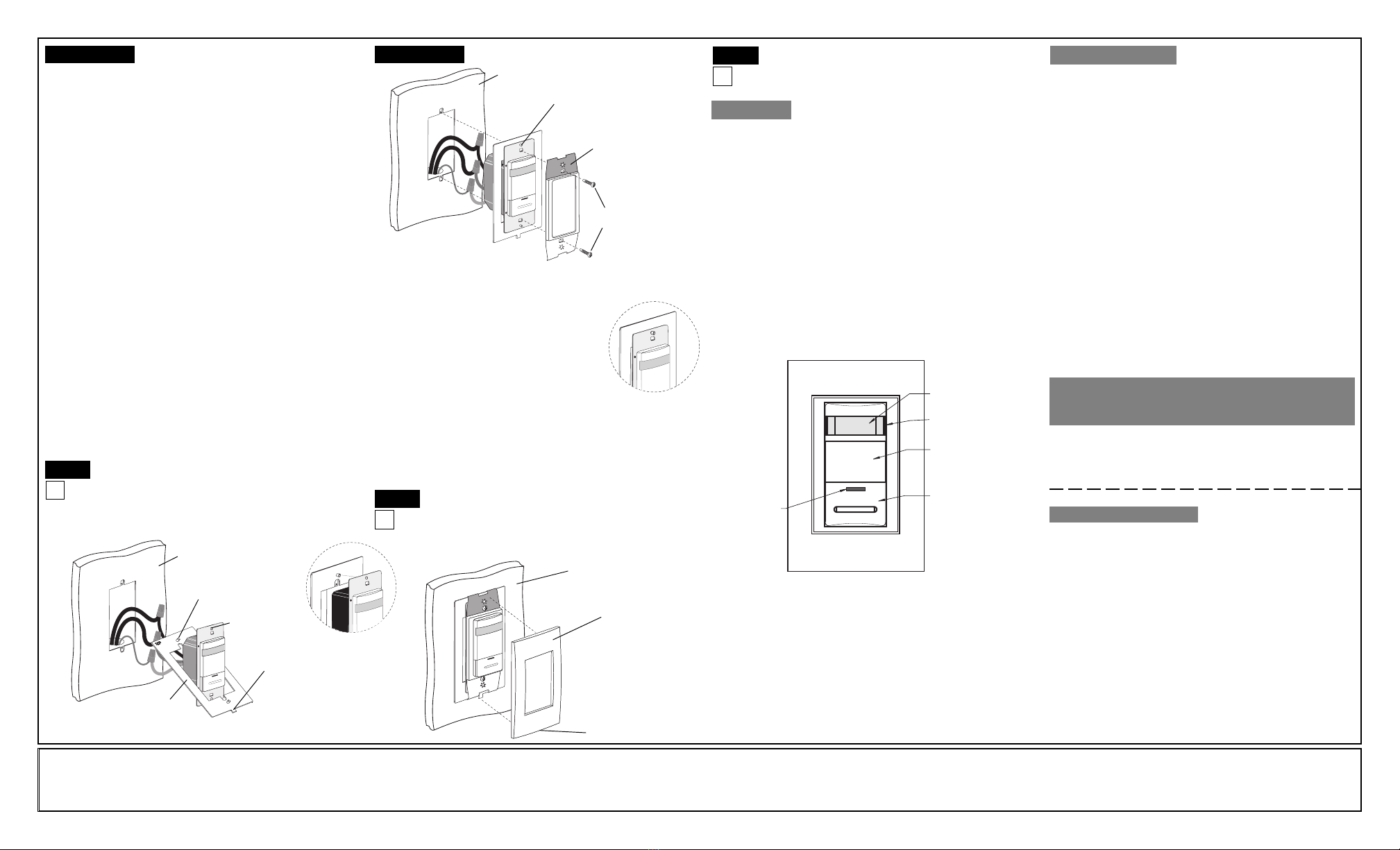
Sensor Mounting:
TURN OFF POWER AT CIRCUIT
BREAKER OR FUSE.
NOTE: This device must be installed with the AcentiTM
Alignment Plate. The Alignment Plate is packaged with
the AcentiTM Wallplate, which is sold separately from this
device.
Control Panel
Cover
Push Button
Lens
LED
Window
Blinders
Step 6
Step 6 cont’dStep 5 cont’d Testing your Sensor prior to
completely mounting in wall box:
NOTE: Dress wires with a bend as shown in diagram in order to relieve
stress when mounting device. Ensure tab of Alignment Plate is on bottom.
Sensor Mounting: Step 8
Wall Surface
Alignment Pin
(2 places)
Alignment Hole
(2 places)
Alignment Plate
Tab
TOP
Wall Surface
Pin and alignment hole
engaged (2 places)
Mounting Screw
(2 places)
Adapter Plate
TOP
Wall Surface
Wallplate
Notch on bottom
TOP
Alignment Pin into
alignment hole
Wallplate Mounting:
Mounting: With notch facing down, press on Acenti™
wallplate (sold separately).
Removal (if necessary): Using a small screwdriver,
place in notch in bottom of wallplate and gently lift up to remove.
Step 7
Strap must sit flat on
alignment plate
TOP
•Position all wires to provide room in outlet wall box for device.
•Ensure that the word "TOP" is facing up on both the alignment plate
and device strap.
•Feed device through center opening of Alignment
Plate and position device so that the alignment
holes fit on alignment pins as shown. Press
device onto Alignment Plate until strap sits flat.
•Align the two star patterned alignment holes of
the Adapter Plate over the two pins of the Alignment
Plate. Gently press Adapter Plate onto Alignment
Plate until Adapter Plate sits flat.
•Tighten mounting screws into wall box so that device
remains flat on Alignment Plate.
NOTE: For multi-device applications, refer to Wallplate Instruction Sheet.
CAUTION: DO NOT over-tighten device mounting screws. Over-
tightening will cause improper mounting and alignment. Using a high-
torque power screwdriver is not recommended. Alignment Plate must
sit flush on wall surface.


