esera automation 1-Wire Hub III DC User manual

All rights reserved. Reproduction as well as electronic duplication of this user guide, complete or in part, requires the written consent of
ESERA GmbH. Errors and technical modification subject to change. ESERA GmbH, ESERA-Automation 2020
www.esera.de 11322 V2.0 R1.1 Manual Page 1 of 6
Art. No. 11322
User Guide
1-Wire Hub III DC
Central power supply for 1-Wire
i
Network and all
ESERA Modules
18 –36 VDC power supply (adapted to PLC
typical 24 VDC)
Filtered power supplies for trouble-free bus
supply
Top-hat rail case for switchboard assembly
Top-hat rail case, width 71 mm
Monitoring of output voltages and currents via
1-Wire module
Screw-based connection
Easy to assemble
Energy efficient design with high efficiency
1 Introduction
Before you start assembling the 1-Wire Hub III DC and before you take the device into operation, please
read this assembly and operating instruction carefully to the end, especially the section referring to the safety
notes.
2 Product description
The 1-Wire Hub III DC serves as the central power supply within a 1-Wire network. The 1-Wire Hub III DC is
providing the required bus voltage (5 V / 12 V) and also distributes the 1-Wire data line. The 1-Wire Hub III DC is
normally required only once in a network and is connected directly to a 1-Wire Bus Coupler or 1-Wire Controller.
Due to the input voltage range of 18 –36 V, the device is ideally adapted to the system environment of PLC
controls, for 24 VDC supply.
To operate the 1-Wire Hub III, an upstream system power supply, providing the input voltage of 24 V, e.g. a DIN
rail power supply, is necessary.
The 1-Wire Hub III DC is equipped with a measuring function for the output voltage and current of the 5 V and 12
V output by default. This is measured by an integrated 1-Wire module (DS2450). Due to voltage- and current
measurements, issues with the supply of a 1-Wire network, such as overload or short circuit, may be detected at
an early stage.
The 1-Wire Hub III DC is designed for a broad supply range of 18 –36 VDC (nominal 24 VDC).
As an "emergency power supply" for a 1-Wire network, the 5 V input voltage is provided in only one direction to
the output, even when there is no 24 V supply voltage available. This is to ensure a minimum function of the
1-Wire network, even in the event of failure of the 24 V main supply. In this operating mode the 12 V voltage is
not available.
Output power of the 1-Wire Hub III DC is designed to hold up to 40 modules.
8 devices of 1-Wire air quality sensors (11127) and 8 devices of 1-Wire 8-way switch modules (11220 (8x8A) or 6
devices of 11228 (8x16A)) can be connected.
The device is designed for DIN top-hat rail mounting in a switchboard.

All rights reserved. Reproduction as well as electronic duplication of this user guide, complete or in part, requires the written consent of
ESERA GmbH. Errors and technical modification subject to change. ESERA GmbH, ESERA-Automation 2020
www.esera.de 11322 V2.0 R1.1 Manual Page 2 of 6
3 Auto-E-Connect® Support
The ESERA Auto-E-Connect® 1-Wire Plug and Play system will be used for the
1-Wire Bus supported. This enables fully automatic configurations of 1-Wire sensors
and actuators on the 1-Wire bus. It is optimized for industrial applications and
enables significant added value beyond the sensor and chip data.
The Auto-E-Connect function automatically recognizes ESERA chips, sensors and actuators, starts suitable
libraries and outputs fully formatted data.
The Auto-E-Connect functionality will be available from mid-2020 via 1-Wire Controllers, 1-Wire Gateways and
1-Wire ECO from ESERA available.
Further information on ESERA Auto-E-Connect can be found on the ESERA website, ESERA Config-Tool 3, or in
the download area for this article in the ESERA Webshop.
4 Technical data
1-Wire function: DS2450 commands, current and voltage output measurement
Port function: Port 0 = current 12 V (12 Bit, 5 V)
Port 1 = voltage 12V (12 Bit, 5 V)
Port 2 = current 5V (12 Bit, 5 V)
Port 3 = voltage 5V (12 Bit, 5 V)
Input voltage: typ. 24 V DC (18 –36 V DC)
Energy Efficiency: >= 90 %
Output Power: max. 15W
Output: 5 V maximum 0,5 A
12 V maximum 1 A (in total for 5 V and 12 V maximum 15W)
Indicator: Power LED (5 V) and 1-Wire activity
Interfaces: Input for 1-Wire Controller or 1-Wire Bus Coupler
Output for 3 x 1-Wire network (output 1 adjacent top-hat rail modules)
Function: The devices has no repeater function for 1-Wire data lines
Outputs are connected internally.
Connection: Screw terminals up to 2.5 qmm cable cross section
Auto-E-Connect: will be supported
5 Ambient conditions
Protection system: IP20
Protection class: III
Temperature, operation: -10°C to +50°C
Air humidity: 10 - 92% (non condensing)
Dimensions: 71 x 71 x 90 mm (WxHxD)
Weight: 174 g
6 Conformity
EN 50090-2-2
EN 61000-4-2, ESD
EN 61000-4-3, HF
EN 61000-4-4, Burst
EN 61000-4-5, Surge
EN 61000-6-1, Fault-free operation
EN 61000-6-3, Stray radiation
RoHS
7 LED indicators
The module has different display LED`s. Please refer to the following table for their functions:
LED status
Description
Function
LED green
Power
Display for 5 V output voltage (if LED is lit, 12 V output voltage is
available due to the system)
LED green
Data
Flashes at 1-Wire activity
Is permanently lit if 1-Wire Bus Coupler is missing or input is
not connected
Is permanently lit in case of a short circuit of one of the 1-
Wire outputs

All rights reserved. Reproduction as well as electronic duplication of this user guide, complete or in part, requires the written consent of
ESERA GmbH. Errors and technical modification subject to change. ESERA GmbH, ESERA-Automation 2020
www.esera.de 11322 V2.0 R1.1 Manual Page 3 of 6
Art. No. 11322
8 Software
Output voltage and current are measured by an integrated module. The module is addressed by a standard
command for the DS2450 module. Data output is provided either as Integer values (0 - 4095) or direct voltages,
depending on the used software product. Please refer to the following formulas depending on the data output:
Calculation with output of DS2450 values in Integer
DS2450, 5 V range, output Integer 0-4096 (12 Bit resolution)
voltage 5 V = ((5,0 / 4096) * 1.11) * DS2450_Port3
voltage 12 V = ((5,0/ 4096) * 2.63) * DS2450_Port1
current 5 V = (5,0 / 4096) * (DS2450_Port2 –20) * 46
current 12 V = (5,0 / 4096) * (DS2450_Port0 –20) * 46
Calculation with output of DS2450 analog values in mV
DS2450, 5 V range, 12 Bit resolution
voltage 5 V = (DS2450_Port3 * 1.11) / 10
voltage 12 V = (DS2450_Port1 * 2.63) / 10
current 5 V (mA) = DS2450_Port2 / 20
current 12 V (mA) = DS2450_Port0 / 22
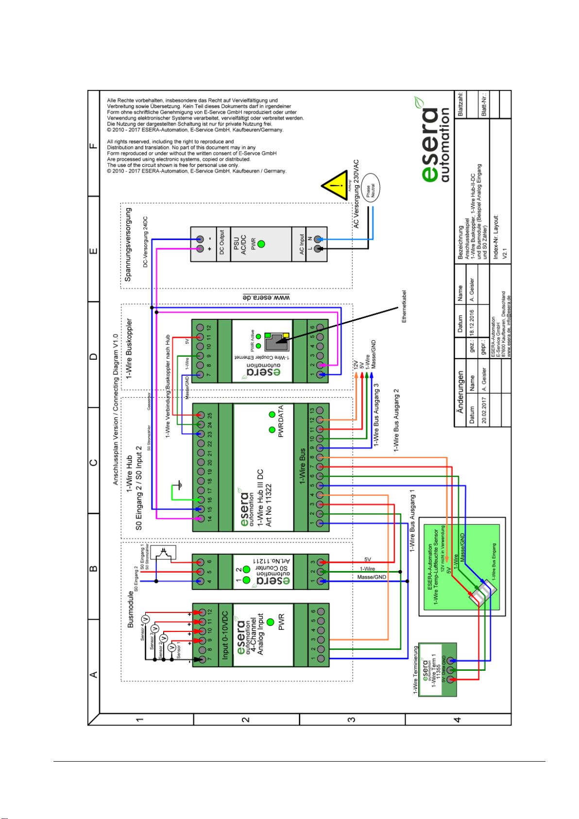
9 Connection plan
A connection plan and a connection example with further modules are available in our webshop.
Pin assignment input, power supply, Bus Coupler/Controller
14 = plus supply voltage
15 = minus supply voltage
16 = grounding (PE)
23 = Ground 1-Wire input
24 = 1-Wire data line
25 = 5 V input from master (e.g. 1-Wire
Controller or 1-Wire Bus Coupler)
Pin assignment output, 1-Wire
network
1 = Ground / GND
2 = 1-Wire data line
3 = 5 V output maximum 0,5 A
4 = 12 V output maximum 1 A
5 = Ground / GND
6 = 1-Wire data line
7 = 5 V output maximum 0,5 A
8 = 12 V output maximum 1 A
9 = Ground / GND
10 = 1-Wire data line
11 = 5 V output maximum 0,5 A
12 = 12 V output maximum 1 A
13 = not connected
The "1-Wire Bus output 1" is specially designed to supply modules close to the 1-Wire Hub III. This output
is equipped with a cable length-compensation compared to cable lengths of the outputs 2 and 3.
Note:
5 V input voltage (terminal 25) is available at the output as "emergency power supply" even in case there is no 24
V power supply available at the output of the 1-Wire Hub.
Note: You can find the basics and tips for the 1-Wire Bus system in the ESERA Online Shop at
1-Wire basics or please refer to our eBook in the shop under Training/Documentation
All rights reserved. Reproduction as well as electronic duplication of this user guide, complete or in part, requires the written consent of
ESERA GmbH. Errors and technical modification subject to change. ESERA GmbH, ESERA-Automation 2020
www.esera.de 11322 V2.0 R1.1 Manual Page 4 of 6
10 Connection - Example
Example with 1-Wire Controller or 1-Wire Gateway, 1-Wire Hub III, Dual Digital Output and 8-fold digital input.

All rights reserved. Reproduction as well as electronic duplication of this user guide, complete or in part, requires the written consent of
ESERA GmbH. Errors and technical modification subject to change. ESERA GmbH, ESERA-Automation 2020
www.esera.de 11322 V2.0 R1.1 Manual Page 5 of 6
Art. No. 11322
11 Operating conditions
The operation of the assembly group can take place only on condition of observing the required voltage and
the ambient conditions. The operating position of the device is irrelevant. The device is meant to be used in
dry and dust-free areas.
If condensation forms, wait for at least 2 hours to acclimatise.
The modules may only be put into operation under the supervision of a qualified electrician. Do not operate the
module in an environment in which flammable gases, vapours or dust are present or can be present.
12 Assembly
The location of the assembly must be protected against humidity. The device is designed to be assembled as
a fixed device within a switchboard.
13 Disposal note
Do not dispose of the device within the household waste!
According to the directive concerning old electrical and electronic appliances,
electronic devices must be disposed of via the collecting points for old electronic
appliances!
14 Safety instructions
When using products that come into contact with electrical voltage, the valid VDE regulations must be observed, especially
VDE 0100, VDE 0550/0551, VDE 0700, VDE 0711 and VDE 0860
All final or wiring work must be carried out with the power turned off.
Before opening the device, always unplug or make sure that the unit is disconnected from the mains.
Components, modules or devices may only be put into service if they are mounted in a contact proof housing.
During installation they must not have power applied.
Tools may only be used on devices, components or assemblies when it is certain that the devices are disconnected
from the power supply and electrical charges stored in the components inside the device have been discharged.
Live cables or wires to which the device or an assembly is connected, must always be tested for insulation faults or
breaks.
If an error is detected in the supply line, the device must be immediately taken out of operation until the faulty cable
has been replaced.
When using components or modules it is absolutely necessary to comply with the requirements set out in the
accompanying description specifications for electrical quantities.
If the available description is not clear to the non-commercial end-user what the applicable electrical characteristics
for a part or assembly are, how to connect an external circuit, which external components or additional devices can
be connected or which values these external components may have, a qualified electrician must be consulted.
It must be examined generally before the commissioning of a device, whether this device or module is basically
suitable for the application in which it is to be used.
In case of doubt, consultation with experts or the manufacturer of the components used is absolutely necessary.
For operational and connection errors outside of our control, we assume no liability of any kind for any resulting
damage.
Kits should be returned without their housing when not functional with an exact error description and the
accompanying instructions. Without an error description it is not possible to repair. For time-consuming assembly or
disassembly of cases charges will be invoiced.
During installation and handling of components which later have mains potential on their parts, the relevant VDE
regulations must be observed.
Devices that are to be operated at a voltage greater than 35 VDC / 12mA, may only be connected by a qualified
electrician and put into operation.
Commissioning may only be realized if the circuit is built into a contact proof housing.
If measurements with an open housing are unavoidable, for safety reasons an isolating transformer must be
installed upstream or a suitable power supply can be used.
After installing the required tests according to DGUV / regulation 3 (German statutory accident insurance,
https://en.wikipedia.org/wiki/German_Statutory_Accident_Insurance) must be carried out.

All rights reserved. Reproduction as well as electronic duplication of this user guide, complete or in part, requires the written consent of
ESERA GmbH. Errors and technical modification subject to change. ESERA GmbH, ESERA-Automation 2020
www.esera.de 11322 V2.0 R1.1 Manual Page 6 of 6
15 Warranty
ESERA GmbH guarantees that the goods sold at the time of transfer of risk to be free from material and workmanship
defects and have the contractually assured characteristics. The statutory warranty period of two years begins from date of
invoice. The warranty does not extend to the normal operational wear and normal wear and tear. Customer claims for
damages, for example, for non-performance, fault in contracting, breach of secondary contractual obligations,
consequential damages, damages resulting from unauthorized usage and other legal grounds are excluded. Excepting to
this, ESERA GmbH accepts liability for the absence of a guaranteed quality resulting from intent or gross negligence.
Claims made under the Product Liability Act are not affected.
If defects occur for which the ESERA GmbH is responsible, and in the case of replacement goods, the replacement is
faulty, the buyer has the right to have the original purchase price refunded or a reduction of the purchase price.
ESERA GmbH accepts liability neither for the constant and uninterrupted availability of the ESERA GmbH or for technical
or electronic errors in the online offer.
We are constantly developing our products further and reserve the right to make changes and improvements to any of the
products described in this documentation without prior notice. Should you require documents or information on older
16 Trademarks
All mentioned designations, logos, names and trademarks (including those which are not explicitly marked) are
trademarks, registered trademarks or other copyright or trademarks or titles or legally protected designations of their
respective owners and are hereby expressly recognized as such by us. The mention of these designations, logos, names
and trademarks is made for identification purposes only and does not represent a claim of any kind on the part of
ESERA GmbH on these designations, logos, names and trademarks. Moreover, from their appearance on ESERA GmbH
webpages it cannot be concluded that designations, logos, names and trademarks are free of commercial property rights.
ESERA and Auto-E-Connect are registered trademarks of ESERA GmbH.
17 Contact
ESERA GmbH
Adelindastrasse 20
87600 Kaufbeuren
GERMANY
Tel.: +49 8341 999 80-0
Fax: +49 8341 999 80-10
www.esera.de
WEEE-Number: DE30249510
i
1-Wire is a product name of Maxim Integrated Products, Inc., USA. Further information
at http://www.maxim-ic.com
This manual suits for next models
1
Table of contents
Other esera automation Control Unit manuals


Popular Control Unit manuals by other brands


Altec Lansing
Altec Lansing 1783 SIGNAL PROCESSING Specifications

Velleman
Velleman VM106 manual

FutureSmart
FutureSmart MDC-108 installation guide

Whelen Engineering Company
Whelen Engineering Company 295HFSA6 installation guide

vistaCNC
vistaCNC iMachIII P4-S manual

GE
GE IC3645SR4W746HL1 Installation and operation manual