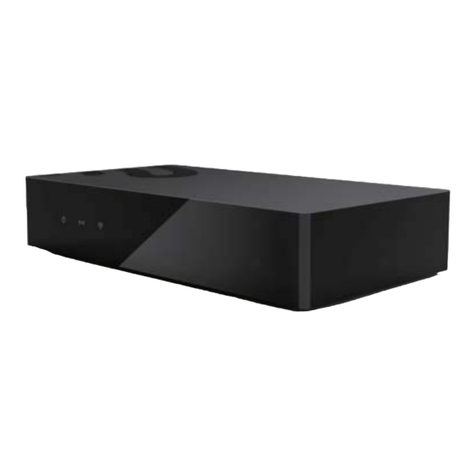
esera automation 11211 User manual

Art. No. 11211
All rights reserved. Reproduction as well as electronic duplication of this user guide, complete or in part, requires the written consent of
ESERA GmbH. Errors and technical modification subject to change. ESERA GmbH, ESERA-Automation 2020
www.esera.de 11211 V2.0 R1.0 Manual Page 1 of 7
User Guide
1-Wire Dual S0 Counter Module
Professional Dual S0 counter module for recording energy meters,
such as electricity, gas, water meters or wind sensors
Readout of meter values via 1-Wire Bus
Permanent data retention of meter values without operating voltage
Counter values can be reset
DIN rail housing with only 17mm width
Designed for control cabinet installation
Connection via screw terminals
Power supply 12VDC
1 Introduction
Before you start assembling the module and before you take the device into operation, please read these
operating instructions carefully to the end, especially the section referring to the safety notes.
2 Product description
The Dual S0 counter module is designed for energy recording of two independent electricity, water and gas
meters or wind turbines. All S0 devices manufactured according to DIN 43864 can be equipped with an isolated
S0 interface can be connected. If in doubt, check the data sheet of your energy measuring device.
After applying the operating voltage, the Dual S0 counter module is ready for operation. The integrated
Counter modules count the input pulses continuously. The counter readings are transmitted via the 1-Wire
Network from the memory of the Dual S0 counter module. The current number of pulses per
Time unit can be calculated by delta formation. Typical readout intervals are in the range of
1 - 3 minutes for electricity or gas meter. The Dual S0 counter module can be set to "zero" by pressing the reset
button.
The Dual S0 counter module is supplied by a 12V DC voltage. The working voltage of the 1-Wire data line is
typically 5V.
After failure of the operating voltage, previously counted input pulses are permanently stored internally.
The Dual S0 counter module counts pulses which are generated by closing an input (falling edge).
One green LED is available for each counter input. The respective LED lights up when the input is closed. A
permanently closed input does not cause any further changes to the counter reading.

All rights reserved. Reproduction as well as electronic duplication of this user guide, complete or in part, requires the written consent of
ESERA GmbH. Errors and technical modification subject to change. ESERA GmbH, ESERA-Automation 2020
www.esera.de 11211 V2.0 R1.0 Manual Page 2 of 7
3 Technical data
1-Wire device: command set DS2423 (Dual Counter)
Operating voltage: 12 V= (+/-10%)
Current consumption: max. 15mA when both LEDs are on
Buffer time counter values: unlimited
Counter size: 2 x 32 Bit Counter, resettable
Interface: 1-Wire Bus (1-Wire Data (5V), 12V and GND)
Connection: screw terminals for 1-wire bus and S0 interface
S0 input: 2 x S0 interface (pulse inputs) for energy meters with isolated
S0 Interface according to DIN 43864
S0 Voltage: working voltage approx. 10VDC with approx. 3mA working current
Counting frequency: max. 300Hz (300 pulses per second)
Length of supply cable S0: It is recommended to use a supply cable between S0 meter and sensor with
max 10m.
When using twisted pair and shielded cables max. 15m,
Depending on the EMC load of the environment, may also be less possible.
LED indicators: 2 x LED green, lights when input is closed
4 Ambient conditions
Temperature, operation: -10°C to +50°C
Humidity: 10 - 92% (non-condensing)
Dimensions: 17 x 71 x 90mm (WxDxH)
Protection system: IP20
Protection class: III
5 Conformity
EN 50090-2-2
EN 61000-4-2, ESD
EN 61000-4-3, HF
EN 61000-4-4, Burst
EN 61000-4-5, Surge
EN 61000-6-1, Interference immunity
EN 61000-6-3, Interference radiation
RoHS
6 LED display
The module has two yellow LED displays, which flash when an input is being closed.
When the input is open, a 5V power is measurable. The edge is being counted during the closing of the input. A
continuously closed input does not cause a modification of the counter readings.
Display
Label
Function
2 x LED
green
Input 1, Input 2
Display of received pulses at the inputs
LED flashes in case of cyclically incoming pulses
LEDs flash continuously, if the respective input is closed.
7 Software / Control
The component is being read out per 1-Wire commands for the DS2423 module. Details for a power counter can
be taken from a sample program in the download area of the shop.
8 Function S0 Interface
The S0 interface is suitable for all types of energy meters and wind turbines and should not be confused with an
S0 interface of ISDN telephone systems.
An S0 interface works according to the principle that e.g. an energy meter provides a defined number of pulses
for a certain amount of energy. Once the number of pulses related to the amount of energy, e.g. an electricity
meter, is known, the current electricity consumption can be calculated very easily.
9 How is an electricity consumption recorded / calculated?
Example: An electricity meter emits 1000 pulses per kW/h. One pulse corresponds to an output of 1W/h. If the
counted impulses are read in every 3 minutes and the delta to the last readout cycle was formed, we know how

Art. No. 11211
All rights reserved. Reproduction as well as electronic duplication of this user guide, complete or in part, requires the written consent of
ESERA GmbH. Errors and technical modification subject to change. ESERA GmbH, ESERA-Automation 2020
www.esera.de 11211 V2.0 R1.0 Manual Page 3 of 7
much energy was consumed in the last 3 minutes. In order to display the power consumption in kW/h, we have to
extrapolate the power consumption to one hour (60 minutes / 3 minutes = factor 20).
We calculate the delta for the current number of pulses from the last and current meter values that we read from
the S0 meter. With a delta of 25 pulses, these correspond to a power consumption of 25 watts in the last 3
minutes.
In 60 minutes, with constant power consumption, there is a consumption of: 25 x 20 = 500W/h
0,5KW/h Power consumption
Calculation
The evaluation cycle of the S0 pulses is 3 minutes.
Factor = 60 minutes / 3 minutes Evaluation cycle
Delta pulses = new pulses - old pulses
Power consumption (KW/h) = (delta * factor) / 1000
Further information can be found, for example, on the Wikipedia website:
https://en.wikipedia.org/wiki/Electricity_meter
https://de.wikipedia.org/wiki/S0-Schnittstelle
10 Data output 1-Wire Controller / 1-Wire Gateway
For the Dual S0 counter module the following data of the 32Bit counter values are output.
The 1-Wire interface of the Dual S0 counter module is controlled by standard commands for the DS2423 block
and the data is read out.
The power of electricity meters, gas or water consumption can be calculated using the continuous meter values
output. A wind sensor can also be evaluated.
Data output:
The data output for the Dual Counter is in the following data format.
1_OWD1_1|Counter value A => Controller no._One Module no._Data set|Counter value 32Bit
1_OWD1_2|Counter value B => Controller no._One Block no._Data set|Counter value 32Bit
Further information on the possibilities and commands can be found in the current documentation 1-Wire
Controller /1-Wire Gateway.
11 Connection plan
The connection plan is
available in the shop as
a separate document.
Operation top side (pulse inputs):
4 = GND/ground
5 = S0 input 1, plus
6 = S0 input 2, plus
Underside (1-Wire Bus):
1 = GND (ground)
2 = 1-Wire Data
3 = 12VDC power supply
Counter Reset button
For details see point 16,
delete counter values

All rights reserved. Reproduction as well as electronic duplication of this user guide, complete or in part, requires the written consent of
ESERA GmbH. Errors and technical modification subject to change. ESERA GmbH, ESERA-Automation 2020
www.esera.de 11211 V2.0 R1.0 Manual Page 4 of 7
12 Connection example 1
Combination of AC meter and Dual S0 counter module
13 Connection example 2
Combination of three-phase meter and Dual S0 counter module

Art. No. 11211
All rights reserved. Reproduction as well as electronic duplication of this user guide, complete or in part, requires the written consent of
ESERA GmbH. Errors and technical modification subject to change. ESERA GmbH, ESERA-Automation 2020
www.esera.de 11211 V2.0 R1.0 Manual Page 5 of 7
14 Connection example 3
Combination of wind sensor and Dual S0 counter module
15 Connection example 4
The following example shows the combination of 1-Wire Controller 20 / 1-Wire Gateway 20 Modbus,
1-Wire Analog Input Module and 1-Wire S0 Dual Counter Module.

All rights reserved. Reproduction as well as electronic duplication of this user guide, complete or in part, requires the written consent of
ESERA GmbH. Errors and technical modification subject to change. ESERA GmbH, ESERA-Automation 2020
www.esera.de 11211 V2.0 R1.0 Manual Page 6 of 7
16 Storage of counter values / Delete counter values
The counter reading of the Dual S0 counter module is stored permanently, even without power supply.
The counter reading can be set to 0 by pressing the reset button for approx. 3 seconds. In order to avoid an
accidental reset of the counter reading, the reset button is recessed on the top of the module. To operate the reset
button, you need a pointed object, such as a match or toothpick.
17 Operating conditions
The module may only be operated at the specified voltages and ambient conditions. The device can be operated
in any position. The device is intended for use in dry and dust-free rooms.
If condensation is formed, allow at least 2 hours for the unit to acclimatize.
The modules may only be put into operation under the supervision of a qualified electrician. Do not operate the
module in an environment in which flammable gases, vapors or dust are present or could be present.
18 Assembly
The installation site must be protected from moisture. The device may only be used in dry indoor areas. The device
is intended for installation inside a control cabinet as a stationary device.
19 Disposal instructions
Do not dispose of the device in domestic waste! Electronic devices are to be disposed of according to
the Directive on waste electrical and electronic equipment (WEEE) on local authorities and
collection points for waste electronic equipment!
20 Safety Instructions
When using products that come into contact with electrical voltage, the valid VDE regulations must be
observed, especially VDE 0100, VDE 0550/0551, VDE 0700, VDE 0711 and VDE 0860
All final or wiring work must be carried out with the power turned off.
Before opening the device, always unplug or make sure that the unit is disconnected from the
mains.
Components, modules or devices may only be put into service if they are mounted in a contact
proof housing. During installation they must not have power applied.
Tools may only be used on devices, components or assemblies when it is certain that the devices
are disconnected from the power supply and electrical charges stored in the components inside the device have
been discharged.
Live cables or wires to which the device or an assembly is connected, must always be tested for insulation faults or
breaks.
If an error is detected in the supply line, the device must be immediately taken out of operation until the faulty cable
has been replaced.
When using components or modules it is absolutely necessary to comply with the requirements set out in the
accompanying description specifications for electrical quantities.
If the available description is not clear to the non-commercial end-user what the applicable electrical characteristics
for a part or assembly are, how to connect an external circuit, which external components or additional devices can
be connected or which values these external components may have, a qualified electrician must be consulted.
It must be examined generally before the commissioning of a device, whether this device or module is basically
suitable for the application in which it is to be used.
In case of doubt, consultation with experts or the manufacturer of the components used is absolutely necessary.
For operational and connection errors outside of our control, we assume no liability of any kind for any resulting
damage.
Kits should be returned without their housing when not functional with an exact error description and the
accompanying instructions. Without an error description it is not possible to repair. For time-consuming assembly or
disassembly of cases charges will be invoiced.
During installation and handling of components which later have mains potential on their parts, the relevant VDE
regulations must be observed.
Devices that are to be operated at a voltage greater than 35 VDC / 12mA, may only be connected by a qualified
electrician and put into operation.
Commissioning may only be realized if the circuit is built into a contact proof housing.
If measurements with an open housing are unavoidable, for safety reasons an isolating transformer must be
installed upstream or a suitable power supply can be used.
After installation the required tests according to DGUV / regulation 3 (German statutory accident insurance,
https://en.wikipedia.org/wiki/German_Statutory_Accident_Insurance) must be carried out.

Art. No. 11211
All rights reserved. Reproduction as well as electronic duplication of this user guide, complete or in part, requires the written consent of
ESERA GmbH. Errors and technical modification subject to change. ESERA GmbH, ESERA-Automation 2020
www.esera.de 11211 V2.0 R1.0 Manual Page 7 of 7
21 Warranty
ESERA GmbH guarantees that the goods sold at the time of transfer of risk to be free from material and workmanship defects
and have the contractually assured characteristics. The statutory warranty period of two years begins from date of invoice.
The warranty does not extend to the normal operational wear and normal wear and tear. Customer claims for damages, for
example, for non-performance, fault in contracting, breach of secondary contractual obligations, consequential damages,
damages resulting from unauthorized usage and other legal grounds are excluded. Excepting to this, ESERA GmbH accepts
liability for the absence of a guaranteed quality resulting from intent or gross negligence. Claims made under the Product
Liability Act are not affected.
If defects occur for which the ESERA GmbH is responsible, and in the case of replacement goods, the replacement is faulty,
the buyer has the right to have the original purchase price refunded or a reduction of the purchase price.
ESERA GmbH accepts liability neither for the constant and uninterrupted availability of the ESERA GmbH or for technical or
electronic errors in the online offer.
We are constantly developing our products further and reserve the right to make changes and improvements to any of the
products described in this documentation without prior notice. Should you require documents or information on older
22 Trademarks
All mentioned designations, logos, names and trademarks (including those which are not explicitly marked) are trademarks,
registered trademarks or other copyright or trademarks or titles or legally protected designations of their respective owners
and are hereby expressly recognized as such by us. The mention of these designations, logos, names and trademarks is
made for identification purposes only and does not represent a claim of any kind on the part of ESERA GmbH on these
designations, logos, names and trademarks. Moreover, from their appearance on ESERA GmbH webpages it cannot be
concluded that designations, logos, names and trademarks are free of commercial property rights.
ESERA and Auto-E-Connect are registered trademarks of ESERA GmbH.
23 Contact
ESERA GmbH
Adelindastrasse 20
87600 Kaufbeuren
GERMANY
Tel.: +49 8341 999 80-0
Fax: +49 8341 999 80-10
www.esera.de
WEEE-Number: DE30249510
Table of contents
Other esera automation Control Unit manuals
Popular Control Unit manuals by other brands

Victaulic
Victaulic 725S Series Installation and operating instructions
ADDAC System
ADDAC System ADDAC200PI Assembly guide

Fisher
Fisher CV500 instruction manual
BIFFI
BIFFI ICON3000 Series Installation, operation and maintenance manual
Zurn Wilkins
Zurn Wilkins ZW205 Maintenance instructions

SEA
SEA 23001157 manual
