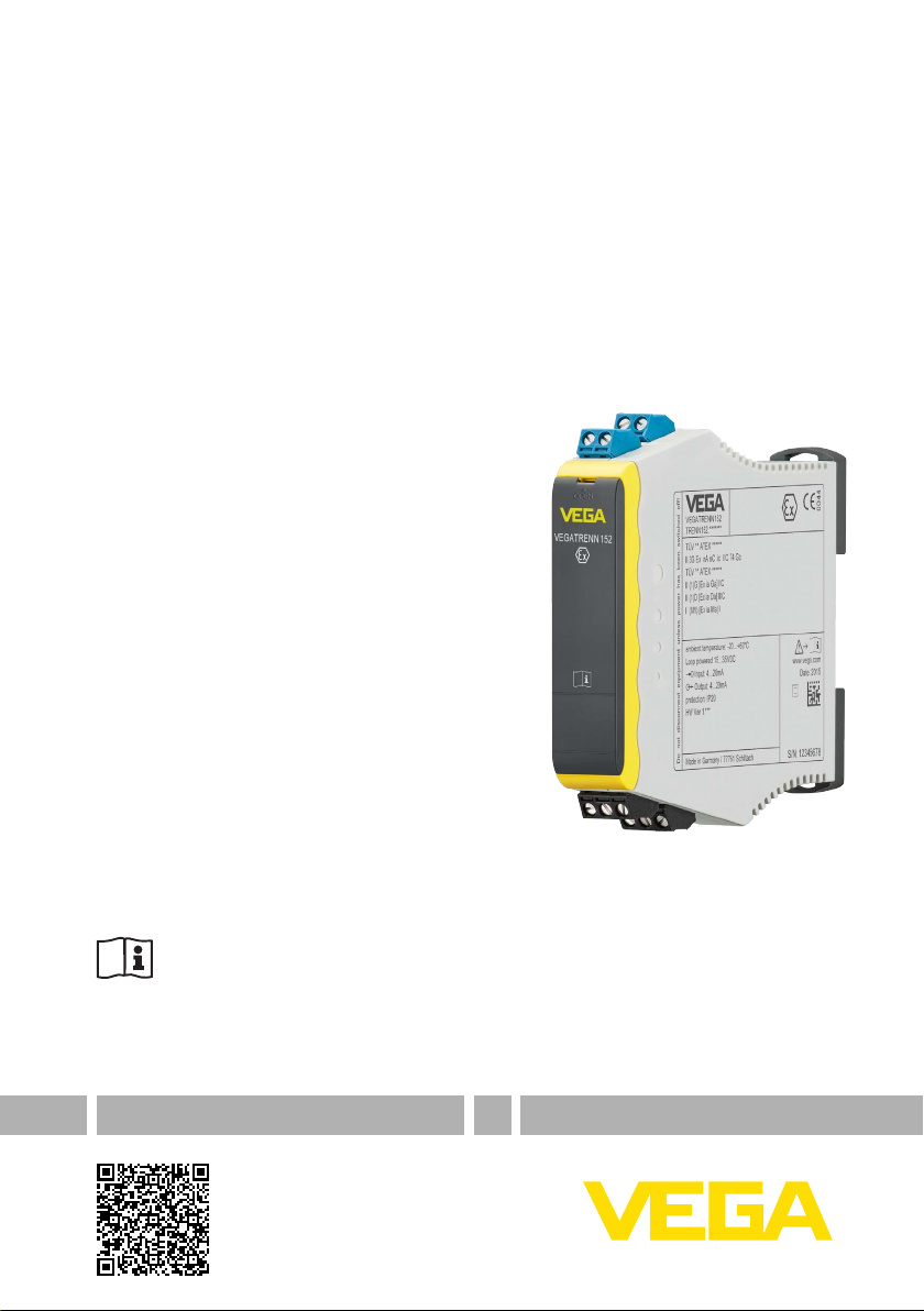
Vega VEGATRENN 152 User manual

Operating Instructions
Double channel separator for 4 … 20 mA
sensors
VEGATRENN 152
Document ID: 50783

2
Contents
VEGATRENN 152 •
50783-EN-210129
Contents
1 About this document ............................................................................................................... 4
1.1 Function ........................................................................................................................... 4
1.2 Target group ..................................................................................................................... 4
1.3 Symbols used................................................................................................................... 4
2 For your safety ......................................................................................................................... 5
2.1 Authorised personnel ....................................................................................................... 5
2.2 Bestimmungsgemäße Verwendung.................................................................................. 5
2.3 Warning about incorrect use............................................................................................. 5
2.4 General safety instructions............................................................................................... 5
2.5 Installation and operation in the USA and Canada ........................................................... 6
2.6 Safety instructions for Ex areas ........................................................................................ 6
3 Product description ................................................................................................................. 7
3.1 Conguration.................................................................................................................... 7
3.2 Principle of operation........................................................................................................ 7
3.3 Adjustment....................................................................................................................... 8
3.4 Packaging, transport and storage..................................................................................... 8
4 Mounting................................................................................................................................... 9
4.1 General instructions ......................................................................................................... 9
5 Connecting to power supply................................................................................................. 10
5.1 Anschluss vorbereiten.................................................................................................... 10
5.2 Anschlussschritte........................................................................................................... 11
5.3 Anschlussplan................................................................................................................ 12
6 Setup ....................................................................................................................................... 13
6.1 Bediensystem ................................................................................................................ 13
6.2 Adjustment elements...................................................................................................... 13
7 Diagnostics and servicing .................................................................................................... 15
7.1 Maintenance .................................................................................................................. 15
7.2 Rectify faults................................................................................................................... 15
7.3 How to proceed if a repair is necessary.......................................................................... 15
8 Dismount................................................................................................................................. 17
8.1 Dismounting steps.......................................................................................................... 17
8.2 Disposal ......................................................................................................................... 17
9 Certicatesandapprovals.................................................................................................... 18
9.1 Approvals for Ex areas ................................................................................................... 18
9.2 EU conformity................................................................................................................. 18
9.3 SIL conformity (optional) ................................................................................................ 18
9.4 Environment management system................................................................................. 18
10 Supplement ............................................................................................................................ 19
10.1 Technical data ................................................................................................................ 19
10.2 Maße.............................................................................................................................. 21
10.3 Industrial property rights................................................................................................. 22
10.4 Trademark ...................................................................................................................... 22

3
Contents
VEGATRENN 152 •
50783-EN-210129
Editing status: 2021-01-27

4
1 About this document
VEGATRENN 152 •
50783-EN-210129
1 About this document
1.1 Function
This instruction provides all the information you need for mounting,
connection and setup as well as important instructions for mainte-
nance,faultrectication,theexchangeofpartsandthesafetyofthe
user. Please read this information before putting the instrument into
operation and keep this manual accessible in the immediate vicinity
of the device.
1.2 Target group
This operating instructions manual is directed to trained personnel.
Thecontentsofthismanualmustbemadeavailabletothequalied
personnel and implemented.
1.3 Symbols used
Document ID
This symbol on the front page of this instruction refers to the Docu-
ment ID. By entering the Document ID on www.vega.com you will
reach the document download.
Information, note, tip: This symbol indicates helpful additional infor-
mation and tips for successful work.
Note: This symbol indicates notes to prevent failures, malfunctions,
damage to devices or plants.
Caution: Non-observance of the information marked with this symbol
may result in personal injury.
Warning: Non-observance of the information marked with this symbol
may result in serious or fatal personal injury.
Danger: Non-observance of the information marked with this symbol
results in serious or fatal personal injury.
Ex applications
This symbol indicates special instructions for Ex applications.
• List
The dot set in front indicates a list with no implied sequence.
1 Sequence of actions
Numbers set in front indicate successive steps in a procedure.
Battery disposal
This symbol indicates special information about the disposal of bat-
teries and accumulators.

5
2 For your safety
VEGATRENN 152 •
50783-EN-210129
2 For your safety
2.1 Authorised personnel
All operations described in this documentation must be carried out
onlybytrained,qualiedpersonnelauthorisedbytheplantoperator.
During work on and with the device, the required personal protective
equipment must always be worn.
2.2 Bestimmungsgemäße Verwendung
Das VEGATRENN 152 ist ein [EEx ia]-Trennübertrager ohne separate
Spannungsversorgung zum Anschluss von 4 … 20 mA/HART-Sen-
soren in Zweileiterausführung.
DetaillierteAngabenzumAnwendungsbereichndenSieinKapitel
"Produktbeschreibung".
Die Betriebssicherheit des Gerätes ist nur bei bestimmungsgemäßer
Verwendung entsprechend den Angaben in der Betriebsanleitung
sowie in den evtl. ergänzenden Anleitungen gegeben.
2.3 Warning about incorrect use
Inappropriate or incorrect use of this product can give rise to applica-
tion-specichazards,e.g.vesseloverllthroughincorrectmounting
or adjustment. Damage to property and persons or environmental
contamination can result. Also, the protective characteristics of the
instrument can be impaired.
2.4 General safety instructions
This is a state-of-the-art instrument complying with all prevailing
regulations and directives.The instrument must only be operated in a
technicallyawlessandreliablecondition.Theoperatorisresponsi-
ble for the trouble-free operation of the instrument.When measuring
aggressive or corrosive media that can cause a dangerous situation
if the instrument malfunctions, the operator has to implement suitable
measures to make sure the instrument is functioning properly.
The safety instructions in this operating instructions manual, the na-
tional installation standards as well as the valid safety regulations and
accident prevention rules must be observed by the user.
For safety and warranty reasons, any invasive work on the device
beyond that described in the operating instructions manual may be
carried out only by personnel authorised by the manufacturer. Arbi-
traryconversionsormodicationsareexplicitlyforbidden.Forsafety
reasons,onlytheaccessoryspeciedbythemanufacturermustbe
used.
To avoid any danger, the safety approval markings and safety tips on
the device must also be observed.

6
2 For your safety
VEGATRENN 152 •
50783-EN-210129
2.5 Installation and operation in the USA and
Canada
This information is only valid for USA and Canada. Hence the follow-
ing text is only available in the English language.
Installations in the US shall comply with the relevant requirements of
the National Electrical Code (ANSI/NFPA 70).
Installations in Canada shall comply with the relevant requirements of
the Canadian Electrical Code.
2.6 Safety instructions for Ex areas
For Ex applications, only devices with corresponding Ex approval may
beused.ObservetheEx-specicsafetyinstructions.Thesearean
integral part of the operating instructions and are enclosed with every
device with Ex approval.

7
3 Product description
VEGATRENN 152 •
50783-EN-210129
3 Product description
3.1 Conguration
The scope of delivery encompasses:
• VEGATRENN 152
• Documentation
– This operating instructions manual
– Ex-specic"Safety instructions" (depending on the version)
– Ifnecessary,furthercerticates
Thetypelabelcontainsthemostimportantdataforidenticationand
use of the instrument:
• Instrument type
• Information about approvals
• Technical data
• Serial number of the instrument
• QR code for device documentation
• Number code for Bluetooth access
• Manufacturer information
Move to " www.vega.com"andenterinthesearcheldtheserial
number of your instrument.
Thereyoucanndthefollowinginformationabouttheinstrument:
• Order data
• Documentation
• Software
Alternatively,youcanndallviayoursmartphone:
• Scan the QR-code on the type label of the device or
• Enter serial number manually in the VEGA Tools app (available
free of charge in the respective stores)
3.2 Principle of operation
Das VEGATRENN 152 ist ein zweikanaliger [EEx ia]-Trennübertrager
zum Anschluss von zwei 4 … 20 mA/HART-Sensoren in Zweileit-
erausführung. Eine separate Spannungsversorgung ist nicht
erforderlich. Als zugehöriges elektrisches Betriebsmittel stellt es eine
galvanische Trennung zwischen Sensorstromkreis und Auswertstrom-
kreis und dadurch zwischen Ex- und Nicht-Ex-Bereich sicher.
Der vom Sensor geprägte Strom (4 … 20 mA) wird linear und galva-
nisch getrennt zum Ausgang übertragen. Das VEGATRENN 152 ist
für die bidirektionale Übertragung von HART-Signalen geeignet. Das
HART-SignalkannüberdiefrontseitigeingebautenHART-Kommu-
nikationsbuchsenoderüberdieKlemmenfürjedenKanalseparat
abgegrienwerden.
Scope of delivery
Type label
Documents and software
Anwendungsbereich
Funktionsprinzip

8
3 Product description
VEGATRENN 152 •
50783-EN-210129
3.3 Adjustment
NoadjustmentorcongurationofVEGATRENN152isnecessary.A
parameter adjustment of the connected sensors can be carried out
via the HART communication sockets behind the hinged front cover.
Adjustment of the connected sensors is carried out preferably via a
Windows PC with a parameter adjustment software such as PACT-
ware and corresponding DTM. A VEGACONNECT interface adapter
or a HART modem is necessary for connecting the PC.
3.4 Packaging, transport and storage
Your instrument was protected by packaging during transport. Its
capacity to handle normal loads during transport is assured by a test
based on ISO 4180.
The packaging of standard instruments consists of environment-
friendly, recyclable cardboard. For special versions, PE foam or PE
foil is also used. Dispose of the packaging material via specialised
recycling companies.
Transport must be carried out in due consideration of the notes on the
transport packaging. Nonobservance of these instructions can cause
damage to the device.
The delivery must be checked for completeness and possible transit
damage immediately at receipt. Ascertained transit damage or con-
cealed defects must be appropriately dealt with.
Up to the time of installation, the packages must be left closed and
stored according to the orientation and storage markings on the
outside.
Unless otherwise indicated, the packages must be stored only under
the following conditions:
• Not in the open
• Dry and dust free
• Not exposed to corrosive media
• Protected against solar radiation
• Avoiding mechanical shock and vibration
• Storage and transport temperature see chapter " Supplement -
Technical data - Ambient conditions"
• Relative humidity 20 … 85 %
Packaging
Transport
Transport inspection
Storage
Storage and transport
temperature

9
4 Mounting
VEGATRENN 152 •
50783-EN-210129
4 Mounting
4.1 General instructions
Das VEGATRENN 152 ist für Tragschienenmontage (Hutschiene
35 x 7,5 nach DIN EN 50022/60715) konstruiert. Durch die Schutzart
IP20 ist das Gerät zum Einbau in Schaltschränken vorgesehen. Es ist
waagerecht und senkrecht montierbar.
Das VEGATRENN 152 ist ein zugehöriges eigensicheres Betriebsmit-
tel und darf nicht in explosionsgefährdeten Bereichen der Zonen 0/1
installiert werden. Ein gefahrloser Betrieb ist nur bei Beachtung der
Betriebsanleitung und der EU-Baumusterprüfbescheinigung sicherg-
estellt.DasVEGATRENN152darfnichtgeönetwerden.
Beim Einbau muss ein Abstand von 50 mm (Fadenmaß) zu den
eigensicherenKlemmensichergestelltsein.
The instrument is suitable for standard and extended ambient condi-
tions acc. to DIN/EN/IEC/ANSI/ISA/UL/CSA 61010-1.
Makesurethattheenvironmentalandambientconditionsspeciedin
chapter " Technical data" are maintained.
Montagemöglichkeiten
Ambient conditions

10
5 Connecting to power supply
VEGATRENN 152 •
50783-EN-210129
5 Connecting to power supply
5.1 Anschluss vorbereiten
Beachten Sie grundsätzlich folgende Sicherheitshinweise:
Warning:
Nur in spannungslosem Zustand anschließen.
• Nur in spannungslosem Zustand anschließen
• Falls Überspannungen zu erwarten sind, Überspannungss-
chutzgeräte installieren
In explosionsgefährdeten Bereichen müssen die entsprechenden
Vorschriften,Konformitäts-undBaumusterprüfbescheinigungender
Sensoren und der Versorgungsgeräte beachtet werden.
Die Spannungsversorgung erfolgt über die 4 … 20 mA-Sensorleitung
(schleifengespeist). Eine separate Hilfsspannung ist somit nicht er-
forderlich. Der Stromeingang der Auswertung, z. B. eine SPS oder ein
Anzeigeinstrument muss aktiv sein, d. h. die Spannungsversorgung
für die Sensorik und den VEGATRENN 152 zur Verfügung stellen.
DetailszurSpannungsversorgungndenSieinKapitel"Technische
Daten".
Die Spannungsversorgung des VEGATRENN 152 wird mit han-
delsüblichemKabelentsprechenddenlandesspezischenInstalla-
tionsstandards angeschlossen.
StellenSiesicher,dassdasverwendeteKabeldiefürdiemaximal
auftretende Umgebungstemperatur erforderliche Temperaturbestän-
digkeit und Brandsicherheit aufweist.
DieSensorenwerdenmithandelsüblichemzweiadrigemKabelohne
Abschirmung angeschlossen. Falls elektromagnetische Einstreu-
ungen zu erwarten sind, die über den Prüfwerten der EN 61326 für
industrielleBereicheliegen,sollteabgeschirmtesKabelverwendet
werden.
LegenSiedieKabelschirmungbeidseitigaufErdpotenzial.ImSensor
muss die Abschirmung direkt an die innere Erdungsklemme ange-
schlossen werden. Die äußere Erdungsklemme am Sensorgehäuse
muss niederimpedant mit dem Potenzialausgleich verbunden sein.
Falls Potenzialausgleichsströme zu erwarten sind, muss die Verbind-
ungaufderAuswerteseiteübereinenKeramikkondensator(z.B.
1 nF, 1500 V) hergestellt werden. Die niederfrequenten Potenzialaus-
gleichsströme werden nun unterbunden, die Schutzwirkung für die
hochfrequenten Störsignale bleibt dennoch erhalten.
Bei Ex-Anwendungen sind die entsprechenden Errichtungsvorschrif-
ten zu beachten. Insbesondere ist sicherzustellen, dass keine Po-
tenzialausgleichsströmeüberdieKabelschirmungießen.Dieskann
bei der beidseitigen Erdung durch den zuvor beschriebenen Einsatz
einesKondensatorsoderdurcheinenseparatenPotenzialausgleich
erreicht werden.
Sicherheitshinweise
Sicherheitshinweise
für Ex-Anwendun-
gen
Spannungsversorgung
Anschlusskabel
Kabelschirmung und
Erdung
Anschlusskabel für
Ex-Anwendungen

11
5 Connecting to power supply
VEGATRENN 152 •
50783-EN-210129
DasGerätverfügtüberfrontseitigeKommunikationsbuchsenzumAn-
schluss eines VEGACONNECT oder sonstigen HART-Bediengeräts
sowie einen integrierten HART-Widerstand.
Ist der Widerstand des angeschlossenen Auswertsystems kleiner
230Ω,wirddasdigitaleBediensignalstarkgedämpftbzw.kurzge-
schlossen.DiedigitaleKommunikationmitdemPCistsomitnicht
mehr möglich. Bei diesen niederohmigen Auswertsystemen muss
deshalbeinWiderstandvonca.230Ωindie4…20mA-Leitung
eingeschleift werden. Dieser Widerstand ist im VEGATRENN 152
bereits integriert und kann über die Auswahl der entsprechenden
Anschlussklemmen ausgewählt werden.
Information:
Beachten Sie bei Verwendung des HART-Widerstandes, dass an
diesemeinzusätzlicherSpannungsabfallentsteht.DetailsndenSie
hierzuinKapitel"Technische Daten".
Im Sensorstromkreis ist für den direkten Anschluss eines HART-
Masters kein zusätzlicher Widerstand nötig. Beim Anschluss eines
VEGADIS82mussderKommunikationswiderstandimVEGADIS82
deaktiviert werden.
Note:
Es ist möglich, bis zu fünf HART-Sensoren an ein VEGATRENN 152
anzuschließen. Es können zwar auch mehrere VEGATRENN auf der
Auswerteseite parallel z. B. an einen SPS-Eingang angeschlossen
werden, die Anzahl der max. anschließbaren HART-Sensoren ist
dennoch auf insgesamt max. fünf begrenzt, da alle zusammenge-
schalteten VEGATRENN einen gemeinsamen Bus bilden.
5.2 Anschlussschritte
Die steckbaren Anschlussklemmen können bei Bedarf zum beque-
men Anschluss abgezogen werden. Zum elektrischen Anschluss
gehen Sie wie folgt vor:
1. GerätwieimvorherigenKapitelbeschriebenmontieren
2. Sensorleitung2anKlemme4/5anschließen,ggf.Abschirmung
auegen
3. Sensorleitung1anKlemme1/2anschließen,ggf.Abschirmung
auegen
4. Auswertstromkreis2,z.B.vonSPSanKlemme14/15oder13/15
(mitHART-Widerstand)anschließen,ggf.Abschirmungauegen
5. Auswertstromkreis1,z.B.vonSPSanKlemme11/12oder10/12
(mitHART-Widerstand)anschließen,ggf.Abschirmungauegen
Der elektrische Anschluss ist somit fertig gestellt.
Note:
Sollen mehrere Sensoren im HART-Multidropbetrieb angeschlos-
sen werden, muss jedem Sensor vor dem Anschluss an das
VEGATRENN 152 eine entsprechende HART-Adresse zugewiesen
werden.
HART-Kommunikation

12
5 Connecting to power supply
VEGATRENN 152 •
50783-EN-210129
5.3 Anschlussplan
1
3
4
5
6
7
13 14 15
2
4 5
10 11 12
-+
12
-
-
+
+H
-
-
+
+H
-+
1 Sensorstromkreis 1 (4 … 20 mA/HART, Ex-Bereich)
2 Sensorstromkreis 2 (4 … 20 mA/HART, Ex-Bereich)
3 HART-Kommunikationsbuchsen zum Anschluss eines HART-Bedi-
engerätes, z. B. VEGACONNECT
4 Auswertstromkreis 1 (4 … 20 mA/HART, passiver Ausgang)
5 Auswertstromkreis 1 (4 … 20 mA/HART, passiver Ausgang mit einge-
schleiftem HART-Widerstand)
6 Auswertstromkreis 2 (4 … 20 mA/HART, passiver Ausgang)
7 Auswertstromkreis 2 (4 … 20 mA/HART, passiver Ausgang mit einge-
schleiftem HART-Widerstand)
Information:
Die Anschlussklemmen können bei Bedarf nach vorne abgezogen
werden. Dies kann bei beengten Platzverhältnissen oder für den
Austausch eines Gerätes sinnvoll sein.

13
6 Setup
VEGATRENN 152 •
50783-EN-210129
6 Setup
6.1 Bediensystem
1
2
3
Fig. 1: Anzeige- und Bedienelemente
1 HART-Kommunikationsbuchsen Kanal 1
1 HART-Kommunikationsbuchsen Kanal 2
3 Aufklappbare Frontblende
6.2 Adjustment elements
The adjustment elements are located under a hinged front cover. To
open it, use a small screwdriver in conjunction with the slot on the
upper side of the front cover.To close it, push the cover at bottom and
toprmlyontothefrontcoveruntilyouhearthetworetainingclips
snap in.
AmVEGATRENN152selbstistkeineBedienungoderKonguration
erforderlich.ÜberdieHART-KommunikationsbuchsenkanneinePar-
ametrierung der angeschlossenen HART-Sensoren ohne Unterbrech-
nung des Messkreises vorgenommen werden. Der für diesen Zweck
benötigteWiderstand(230Ω)istbeimAnschlussderKlemmen10/12
Front cover
HART-Kommunikations-
buchsen

14
6 Setup
VEGATRENN 152 •
50783-EN-210129
(Kanal1)bzw.13/15(Kanal2)bereitsimVEGATRENN152integriert.
Die Bedienung des angeschlossenen Sensors erfolgt über einen
Windows-PC mit einer Parametrierungssoftware, wie z. B. PACTware
und entsprechendem DTM.

15
7 Diagnostics and servicing
VEGATRENN 152 •
50783-EN-210129
7 Diagnostics and servicing
7.1 Maintenance
If the device is used properly, no special maintenance is required in
normal operation.
The cleaning helps that the type label and markings on the instrument
are visible.
Take note of the following:
• Use only cleaning agents which do not corrode the housings, type
label and seals
• Use only cleaning methods corresponding to the housing protec-
tion rating
7.2 Rectify faults
The operator of the system is responsible for taking suitable meas-
ures to rectify faults.
Das Gerät bietet Ihnen ein Höchstmaß an Funktionssicherheit. Den-
noch können während des Betriebes Störungen auftreten. Diese
können z. B. folgende Ursachen haben:
• Messwert vom Sensor nicht korrekt
• Spannungsversorgung
• Störungen auf den Leitungen
Therstmeasuretobetakenistochecktheinput/outputsignalas
well as the power supply. In many cases, the causes can be deter-
minedandfaultscanbequicklyrectied.
Depending on the reason for the fault and the measures taken, the
steps described in chapter " Setup" must be carried out again or must
be checked for plausibility and completeness.
Should these measures not be successful, please call in urgent cases
the VEGA service hotline under the phone no. +49 1805 858550.
The hotline is also available outside normal working hours, seven
days a week around the clock.
Sinceweoerthisserviceworldwide,thesupportisprovidedin
English.The service itself is free of charge, the only costs involved are
the normal call charges.
7.3 How to proceed if a repair is necessary
Youcanndaninstrumentreturnformaswellasdetailedinforma-
tion about the procedure in the download area of our homepage:
www.vega.com.
By doing this you help us carry out the repair quickly and without hav-
ing to call back for needed information.
If a repair is necessary, please proceed as follows:
Maintenance
Cleaning
Reaction when malfunc-
tion occurs
Störungsursachen
Faultrectication
Reaction after fault recti-
cation
24 hour service hotline

16
7 Diagnostics and servicing
VEGATRENN 152 •
50783-EN-210129
• Printandlloutoneformperinstrument
• Clean the instrument and pack it damage-proof
• Attach the completed form and, if need be, also a safety data
sheet outside on the packaging
• Please contact the agency serving you to get the address for
thereturnshipment.Youcanndtheagencyonourhomepage
www.vega.com.

17
8 Dismount
VEGATRENN 152 •
50783-EN-210129
8 Dismount
8.1 Dismounting steps
Take note of chapters " Mounting" and " Connecting to voltage sup-
ply" and carry out the listed steps in reverse order.
8.2 Disposal
The device is made of recyclable materials. For this reason, it should
be disposed of by a specialist recycling company. Observe the ap-
plicable national regulations.

18
9Certicatesandapprovals
VEGATRENN 152 •
50783-EN-210129
9 Certicatesandapprovals
9.1 Approvals for Ex areas
Approved versions for use in hazardous areas are available or in
preparation for the device series.
Youcanndtherelevantdocumentsonourhomepage.
9.2 EU conformity
ThedevicefullsthelegalrequirementsoftheapplicableEUdirec-
tives.ByaxingtheCEmarking,weconrmtheconformityofthe
instrument with these directives.
The EU conformity declaration can be found on our homepage.
9.3 SIL conformity (optional)
InstrumentswithSILoptionfullltherequirementsoffunctionalsafety
accordingtoIEC61508.Youcanndfurtherinformationinthesup-
plied Safety Manual.
9.4 Environment management system
Protection of the environment is one of our most important duties.
That is why we have introduced an environment management system
with the goal of continuously improving company environmental pro-
tection.Theenvironmentmanagementsystemiscertiedaccording
toDINENISO14001.Pleasehelpusfullthisobligationbyobserv-
ing the environmental instructions in chapters " Packaging, transport
and Lagestoragerung", " Disposal" of these operating instructions.

19
10 Supplement
VEGATRENN 152 •
50783-EN-210129
10 Supplement
10.1 Technical data
Note for approved instruments
The technical data in the respective safety instructions are valid for approved instruments (e.g. with
Exapproval).Insomecases,thesedatacandierfromthedatalistedherein.
All approval documents can be downloaded from our homepage.
Allgemeine Daten
Bauform Einbaugerät zur Montage auf Tragschiene 35 x 7,5 nach
EN 50022/60715
Gewicht 150 g (5.29 oz)
Gehäusewerksto Polycarbonat PC-FR
Anschlussklemmen
Ʋ Klemmenart Schraubklemme
ƲAderquerschnitt 0,25 mm² (AWG 23) … 2,5 mm² (AWG 12)
Spannungsversorgung
Betriebsspannung 15 … 35 V DC (schleifengespeist)1)
Sensorstromkreis
Anzahl Sensoren 2 x 4 … 20 mA/HART (5 x HART-Multidrop)
Eingangsart Aktiv (Sensorversorgung durch VEGATRENN 152)
Klemmenspannung 16 … 10 V DC bei 4 … 20 mA
KlemmenspannungbeiBetriebsspannung>19V
Ʋbei 4 mA >14,5VDC
Ʋbei 20 mA >14VDC
Spannungsabfall bei 15 V Betriebsspannung
Ʋbei 4 mA < 3 V
Ʋbei 20 mA < 5 V
Leerlaufspannung < 17 V
Kurzschlussstrom ≤27mA
Restwelligkeit < 20 mV RMS
Auswertstromkreis
Anzahl 2 x 4 … 20 mA/HART
Ausgangsart Passiv
Betriebsspannung 15 … 35 V DC
Restwelligkeit des Ausgangsstromes < 40 µA RMS
Strom ohne angeschlossenen Sensor < 500 µA
1) OhneinternenHART-Widerstand(beiAnschlussanKlemme11/12bzw.Klemme14/15)

20
10 Supplement
VEGATRENN 152 •
50783-EN-210129
Messabweichung
Oset < 80 µA bei 25 °C (77 °F)
Referenzbedingungen Kalibriertemperatur25°C(77°F)
Linearität ≤0,15%
EinussderUmgebungstemperatur
ƲIm Bereich +20 … +60 °C
(+68 … +140 °F)
< 0,2 %
ƲIm Bereich -20 … +20 °C
(-4 … +68 °F)
< 0,3 %
Abweichung durch starke, hochfrequente
elektromagnetische Felder (EN 61326)
< 0,5 %
Integrated HART resistor
Resistance value 232Ω
Ambient conditions
Ambient temperature at the installation
site of the instrument
-20 … +60 °C (-4 … +140 °F)
Storage and transport temperature -40 … +70 °C (-40 … +158 °F)
Relative humidity < 96 %
Mechanical environmental conditions
Vibrations (oscillations) Class 4M4 acc. to IEC 60721-3-4 (1 g, 4 … 200 Hz)
Impacts (mechanical shock) Class 6M4 acc. to IEC 60721-3-6 (10 g/11 ms,
30 g/6 ms, 50 g/2.3 ms)
Elektrische Schutzmaßnahmen
Schutzart IP20
Schutzklasse II
Verschmutzungsgrad 2
Elektrische Trennmaßnahmen
Sichere Trennung gemäß VDE 0106 Teil 1 zwischen allen Stromkreisen
ƲBemessungsspannung 253 V
ƲIsolationsfestigkeit 2,2 kV
Approvals
Instrumentswithapprovalscanhavedierenttechnicalspecicationsdependingontheversion.
For that reason the associated approval documents of these instruments have to be carefully
noted.They are part of the delivery or can be downloaded by entering the serial number of your
instrumentintothesearcheldunderwww.vega.com as well as in the general download area.
Other manuals for VEGATRENN 152
1
Table of contents
Languages:
Other Vega Water Filtration System manuals
Popular Water Filtration System manuals by other brands

Saunatec
Saunatec Saunatec Water Filtration System ASX100 Installation & operation manual

Astronics
Astronics Trig-Tek 203M user manual

Crystal Mountain
Crystal Mountain FIL-W300005 installation instructions

Asutec
Asutec ASMU-120 Assembly instruction

JRC
JRC NSVS1123 manual

Nyos
Nyos TORQ Body 0.75 instructions