Certikin SALT EXPERT-3 Series User manual

SALT EXPERT-3 Series
Salt Chlorinator
OPERATING INSTRUCTIONS

SALT EXPERT Salt Chlorinator (V3) Page 2
INDEX
1.0 General Overvie ................................................................................................ 3
2.0 Installation
2.1 Control Box Installation ........................................................................... 3
2.2 Cell Installation ........................................................................................ 3
3.0 Pool Preparation .................................................................................................. 4
4.0 User Panel ........................................................................................................... 5
4.1 Programming (T Model Only) .................................................................. 5
4.2 Chlorine Output ....................................................................................... 7
4.3 User Mode ............................................................................................... 8
4.4 Warnings Display .................................................................................... 8
4.5 Chlorine output level…………….………………………………………...9
4.6 Safety Back Wash .................................................................................. 10
4.7 Run Dry Safety Feature .......................................................................... 10
5.0 General Operation/Pool Chemistry .................................................................... 11
5.1 Setting the right Chlorine Output and Filtration Time. ............................ 11
5.2 Stabiliser. ............................................................................................... 11
5.3 pH Level. ............................................................................................... 11
5.4 Total Alkalinity. ..................................................................................... 11
5.5 Salt Level. .............................................................................................. 11
6.0 Chlorinator Maintenance and Troubleshooting .................................................. 12
6.1 Cell Maintenance. .................................................................................. 12
6.2 Troubleshooting. ............................................................................... 13-14
7.0 Warranty ........................................................................................................... 15

Your Certikin SALT EXPERT Chlorinator orks by co
Congratulations! You have purchased an Certikin S
SALT EXPERT Salt Chlorinator (V3) Page 3
1.0 General O er iew
ALT EXPERT series Chlorinator. Please
read the instructions carefully and your purchase ill provide you ith years of trouble free
use.
nverting some of the salt in your
pool into chlorine hich starts to destroy algae, bacteria and viruses in your pool ater thereby
sanitising your pool. As part of the process, the chlorine is converted back into salt and hence
salt is not consumed.
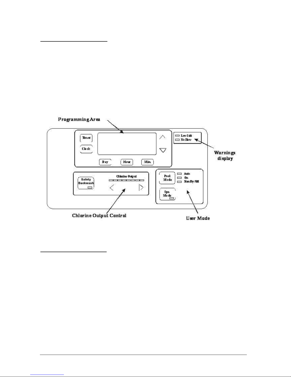
Your SALT EXPERT Chlorinator control has many features to ensure simple operation of your
chlorinator and filtration system. It has a clever Spa mode to ensure that the right level of
chlorine is produced hilst you are enjoying a spa.
Note: The Chlorinator is not intended for use by young children or infirm persons ithout
supervision. Please ensure that young children are supervised to ensure that they do not play
ith the Chlorinator.
2.1 Chlorinator Control Installation
The SALT EXPERT Chlorinator control has a Rating of IP24 enabling it to be installed
outdoors. Regulations require that the control is not allo ed to be located ithin 3 metres of
the pool ater.
The control should be installed in a ell ventilated position ideally a ay from direct sunlight.
Ensure that the unit is not located near pool chemicals as fumes may damage the control.
Included in the kit is t o green masonry plugs and scre s. When installing on a brick or
concrete all, use a 7mm masonry drill. Mounting Scre s should be 180mm apart and located
at least 1500mm above ground level. A drilling template is provided on page 6.
When installing the control on a post, first attach a flat aterproof panel at least 300mm ide
by 500mm long. Make sure the control is located centrally on the panel and sits flat.
Plug the plug into a suitable eatherproof outlet and then plug the pump into the Chlorinator
control.
Note: The pump current rating must not exceed 8 amps.
2.2 Cell Installation
The chlorinator cell must be located last in the pipe ork just prior to the return to the pool. If
valves are installed bet een the Chlorinator and the pool outlet, it is essential that they cannot
deadhead the pump. If the pressure in the cell exceeds 150kPa and/or the ater temperature
exceeds 40 degrees C, the cell may fail.
WARNING: Never install the cell before the pump or heater
The cell must be installed ith the barrel unions underneath and the cell should be horizontal.
50mm fittings have been provided. Make sure that the o’rings are correctly fitted and the
unions are done up tightly.

SALT EXPERT Salt Chlorinator (V3) Page 4
WARNING: It is essential that pipe ork and equipment do not allo gases generated from
the cell to collect and build up.
Once the cell is located, connect the black multi-core cable to the cell. The blue ire must be
connected to the blue terminal. The cable is designed to come from belo the cell. Make sure
ing nuts are correctly tightened to ensure good contact.
3.0 Pool Preparation
The chlorinator requires at least 3000ppm of salt but e suggest you prepare the pool at
4000ppm therefore add 4kg’s of salt for every 1000 litres of ater (a typical pool of around
50,000 litres requires 200kg of salt).
Salt should al ays be added at the shallo end of the pool and allo ed to dissolve. Running
the pump ill mix the ater and speed the dissolving process.
WARNING: Never add salt to the skimmer box!!
NOTE : Plug the pump directly into a po er outlet (bypass the Chlorinator) and run for 8-10
hours to ensure the salt is dissolved prior to running the chlorinator.
When the salt is dissolved, connect the pump to the chlorinator and run it on maximum chlorine
output. Check that the lo salt light is not on. If it is, check again in 24 hours.

SALT EXPERT Salt Chlorinator (V3) Page 5
3.0 User Panel (T Model)
The user panel can be broken do n into 4 separate areas :
- Programming area for setting the clock and on periods(on T models)
- Chlorine Output Controls for setting the chlorine output level and to activate the
Safety Back ash Feature.
- Warnings display to indicate that there is no flo to the cell or there is insufficient
salt in the pool
- User Mode for manual control of the pump/Chlorinator or to select Spa mode.
- Chlorine Production Le el indicates the amount of chlorine being produced.
Once programmed, you ill generally only use the User Mode and Chlorine Output control.
3.0 User Panel (S Model)
The user panel can be broken do n into 4 separate areas :
1. Display Area
2. Chlorine Output Controls for setting the chlorine output level and to activate the
Safety Back ash Feature.
3. Warnings display to indicate that there is no flo to the cell or there is insufficient
salt in the pool
4. User Mode for manual control of the pump/Chlorinator or to select Spa mode.
5. Chlorine Production Le el indicates the amount of chlorine being produced.
Once programmed, you ill generally only use the User Mode and Chlorine Output control.

SALT EXPERT Salt Chlorinator (V3) Page 6
3.1 Programming (T Model only)
Setting Current Time/Day
(a) Select POOL MODE Standby/Off
(b) Press the CLOCK button
(c) Press DAY to change the current day.
(d) Press HOUR to move the Display cursor to the hour digits and then use the Up and
Do n arro s to the right of the display to change the current hour
(e) Press MIN to move the Display cursor to the min digits and then use the up and do n
arro s to the right of the display to change the current minutes
(f) Press the CLOCK button to exit the clock setting mode.
Setting Timers
Your Chlorinator has 4 timers enabling you to set four different periods in hich your
chlorinator/pump ill operate. Different periods can be set for the eekend compared to
eekdays. Timers are set by entering a start time, and a period for ho long you ant to
operate (i.e. Mon – Fri T1 On 14:00 and Mon – Fri T1 Period 6:15 ill run the
chlorinator/pump during eekdays from 14:00 for 6.25 hours). To set timers, do the follo ing:
(g) Select POOL MODE Standby/Off
(h) Press the TIMER button to step to the timer you ant to set
(i) Press DAY button to step from Mon-Fri to Sat-Sun and Visa versa
(j) Press HOUR button to set the hour for the timer selected and use the Up/Do n arro s
to change the time. NOTE: Hour digits go from Not Used and then 0 to 23. If you
don’t ant to use this timer, select Not Used.
(k) Press MIN button to select the minutes for the timer selected and use the Up/Do n
arro s to change the time. Press the TIMER button to select the Period or another time
and set as required.
(l) When finished, press the TIMER button a number of times to scroll through the other
times until you return to normal display. This saves your ne settings.
(m) Select POOL MODE Auto

: Sends a message to other Certikin equipment (i
Certikin recommend that you use t o timers, one f
SALT EXPERT Salt Chlorinator (V3) Page 7
Programming Recommendations
or the morning and one for the evening
and typically for periods of 2-5 hours for each. Your chlorinator is most effective if running in
the early morning or evening hen it is cooler (strong sunlight consumes more chlorine). As a
default, the control is set to come on at 08:00 and 16:00 both for periods of 4 hours.
3.2 Chlorine Output
The Chlorine Output Control area of the user panel has three main functions:
(a) Increase/Decrease arro s for setting the chlorine output level of the chlorinator. The
chlorinator output can be set from levels 1 through to 8. This level only applies to Pool
Mode. When the Chlorinator is in Spa mode, the chlorine output ill be at level 1
(b) Chlorine Output display sho s the level set
(c) The LCD display ill also sho a output level from 1 to 8 hich indicates the
performance of the chlorinator compared to the Chlorine Output LED’s. Should the
LCD output level (1 to 8) be less than the LED output, check salt level in pool. Should
salt level be at 4000 ppm and output more than 2 settings less than LED display, you
cell may need replacing.
3.3 User Mode (T Model only)
The user mode buttons enable you to select Pool or Spa mode and to manually control the
Chlorinator/Pump. Functions are as follo s:
(a) POOL MODE: Sends a message to other AstralPool equipment (if fitted) to go to Pool
mode. There are 3 Pool Modes
Auto The Chlorinator/Pump ill run according to ho you have set the
timers
On The Chlorinator/Pump ill run continuously.
Standby/Off The Chlorinator/Pump ill stay off continuously.
(b) SPA MODE f fitted) to go to Spa
mode and turns the pump on

: Sends a message to other Certikin equipment (if
: Sends a message to other Certikin equipment (i
SALT EXPERT Salt Chlorinator (V3) Page 8
Spa
Mode
Pool
Mode
Auto
Standby/Off
On
Press to Select Pool
Mode.
Repeated pressing
scrolls through
Auto, On and
Standby/Off
Press to Turn
On/Off Spa Mode
Indicates Chlorinator
running off timer settings
Indicates
Chlorinator/Pump
manually on
Indicates
Pump/Chlorinator
manually off
3.3 User Mode (S Model only)
The user mode buttons enable you to select Pool or Spa mode and to manually control the
Chlorinator/Pump. Functions are as follo s:
(c) POOL MODE fitted) to go to Pool
mode.
Auto Not Used
On The Chlorinator/Pump ill run continuously.
Standby/Off The Chlorinator/Pump ill turn off.
(d) SPA MODE f fitted) to go to Spa
mode and turns the pump on
Spa
Mode
Pool
Mode
Auto
Standby/Off
On
Press to Select Pool
Mode.
Repeated pressing
alternates from On
to Standby/Off
Press to Turn
On/Off Spa Mode
Not Used
Indicates
Chlorinator/Pump
manually on
Indicates
Pump/Chlorinator
manually off
3.4 Warnings Display
Apart from messages displayed on the User display, there are t o arning indicators.
(a) LOW SALT: This indicates that the concentration of salt has reduced ithin you pool.
To rectify, add salt at approx. 50kg per 50000 litres of ater (see 3.5 Salt level belo )
(b) NO FLOW: This indicates that the Chlorinator thinks that there is no flo to the cells.
Potential problems/solutions are described in the Diagnostics section.

SALT EXPERT Salt Chlorinator (V3) Page 9
3.5 Chlorine Output Le el
The LED lights on the user panel set the desired output level or chlorine level.
As sho n belo , the bottom right hand corner of the LCD display indicates the actual level as
distinct from the set or desired output indicated by the LED lights.
The chlorinator output, or chlorine production, ill be affected by ater temperature, salt
levels and the input voltage of the chlorinator. When the chlorinator is operating at maximum
efficiency, the Chlorine Output level should al ays be approximately the same level as the Set
Point. The set point can be checked on the LED display hich is divided into 8 sections. If all
8 LED’s are illuminated, out set point is at 8. If only 6 light are illuminated, the set point is 6
Timer
Clock
Day Hour Min.
Your SALT EXPERT Salt chlorinator ill al ays attempt to adjust the output so that the actual
output level matches set point level. At times hen the Chlorine output level is lo er than the
set point, check the salt level in your s imming pool at your local pool shop. Alternatively,
you may have a lo voltage supply to the chlorinator (less than 240Volts) or the ater may be
colder than usual.
Maximum efficiency ill be achieved from you chlorinator at the follo ing levels
Water at 27° C
Voltage at 240V
Salt Level at 4000 PPM
6 +
Chlorine output Le el
Chlorine Output
Safety
Backwash
Chlorine Set Point

SALT EXPERT Salt Chlorinator (V3) Page 10
3.6 Safety Backwash
When back ashing your sand filter, the pool ater does not pass through the cell. During the
back ash and rinse process, most chlorinators ill build up potentially explosive hydrogen gas
in the Chlorinator Cell.
The Safety Back ash function allo s the pump to turn on ithout applying po er to the
Chlorinator Cell. This prevents the build up of hydrogen gas during the back ash and rinse
process. In addition, the Safety Back ash function has set run times after hich the pump ill
automatically turn off. This ill prevent extended back ashing and potential excessive ater
loss from the pool.
To Back Wash and Rinse your filter follo these steps:
1. Press the pool mode button to the “off/standby” mode
2. Turn the Multiport Valve to “Back ash” position
3. Press the Safety back ash button on the user panel – the pump ill no start ithout
applying po er to the chlorinator cell
a. Press once for one minute pump operation
b. Press t ice for t o minute pump operation
c. Press three times for three minute pump operation
d. Press a four times to turn pump off
4. After pump turns off turn the filter multiport valve to Rinse
5. Press the Safety back ash button on the use panel once for a one minute rinse
6. When pump turns off, move the multiport valve back to filter position
7. Press the pool mode button to “Auto” function so that chlorinator ill operate on time
clock settings.
3.7 Run Dry Safety Feature
Your SALT EXPERT Chlorinator incorporates a run dry safety cut out. When the Chlorinator
turns the filter pump on, it ill check for ater flo . If no ater flo is detected ithin 3
minutes, the chlorinator ill turn the pump off. This is designed to protect the pump seal and
parts from overheating if no ater flo is present.
On initial start up, you ill need to prime the pump. In some cases, the pump ill take more
than three minutes to prime and for ater flo to be detected by the chlorinator. If this should
occur, simply start the pump again by pressing the Pool Mode button to “on”.
If during normal operation, the chlorinator s itches the pump off after three minutes, then
check the position of all valves, empty skimmer basket and pump basket and clean the filter.
Please see page 12 for the recommended method of Cell Cleaning.

the inter. Certikin recommend that you initiall
SALT EXPERT Salt Chlorinator (V3) Page 11
4.0 General Operation/Pool Chemistry
4.1 Setting the Right Chlorine Output and Filtration Time
Your SALT EXPERT Chlorinator must be run every day to ensure that your pool is correctly
sanitised. As the sun dissipates chlorine, running times are higher in the summer compared to
y run you chlorinator at maximum output
Summer
You should set your Chlorinator to operate for 8 to 10 hours per day. Ideally, run it for 4-5
hours in the morning (say 8-12pm) and 4-5 hours in the evening (say 6.00-11pm).
In extremely hot eather it may be necessary to extend the running time if you find that the
free chlorine level is too lo .
Winter
You should set your Chlorinator to operate for 6 to 8 hours per day. Again, running it in the
morning and evening is preferable.
Checking Chlorine Le el.
Ideally, check you Chlorine level after the morning operating period. The free chlorine
residual level should be some here bet een 1 and 3 part per million. Increase or decrease the
output of the Chlorinator to get the right residual chlorine level. It may also be necessary to
adjust the operating period if you are running at minimum or maximum output.
4.2 Stabiliser
As previously mentioned, sunlight rapidly dissipates the amount of free chlorine in your pool.
Chlorine stabiliser greatly reduces this effect.
Without stabiliser, you may need to run your Chlorinator and filtration system up to 16 hours
per day longer!!!
Keep the Stabiliser reading bet een 30 and 60ppm.
4.3 pH Le el
You should keep you pH level bet een 7.0 and 7.4 for fibreglass pools and 7.2 to 7.6 for other
pools.
4.4 Total Alkalinity
The ideal range is bet een 80 and 120 ppm.
4.5 Salt Le el
Although salt is not consumed by the Chlorinator, salt is lost during back ashing, and hen
your pool overflo s due to rain or splashing. The correct salt level is important to cell life and
the effective operation of your chlorinator. Salt level should be maintained around 4,000ppm
but should never be allo ed to fall belo 3,000ppm.
A typical pool of around 50,000 litres requires 200kg of salt to initially set-up the pool to
4,000ppm.
A lo salt level arning is indicated on your SALT EXPERT Chlorinator if the salt level
drops. If Lo Salt is indicated, check again in 24 hours and then if it is still indicated, add t o

by Certikin or its service agent or a
SALT EXPERT Salt Chlorinator (V3) Page 12
25kg bags of salt to the shallo end of your pool. Run the filtration system for approx. 6 hours
to help mix the salt in the pool. It can take up to a day for the salt to fully dissolve.
If the lo salt light is still on, then you should get your pool ater tested. If the Salinity is
above 4000ppm then you may need to have your Chlorinator checked.
Warning: Some people recommend that you put salt directly in the skimmer box. This is a
very bad practice as it allo s very high concentrations of salt to be passed through your
filtration and other pool equipment.
5.0 Chlorinator Maintenance and Troubleshooting
If the supply cord is damaged, it must be replaced
similarly qualified person in order to avoid a hazard.
5.1 Cell Maintenance
Your SALT EXPERT Chlorinator has an automatic cleaning feature that under normal
conditions, ill keep the cell plates clear of deposits of salt and calcium.
SALT EXPERT Series cells have a negative charge sensor that monitors the flo and salt
levels of the ater. This sensor is designed to be fail safe. As it is negative charges deposits of
calcium or other debris may be deposited on it and cause it to indicate a lo salt or no flo
condition. Should a lo salt condition be indicated, have your salt level checked at your local
pool shop. If the lo salt condition persists, or a no flo condition is indicated hen the
supply pump is operating, you may need to manually clean your chlorinator Cell.
Cell Cleaning Instructions:
- close applicable valves
- disconnect the Chlorinator from the Mains by removing the plug
- disconnect the cell ires
- undo the barrel nuts connecting the cell to your filtration system.
- turn the cell upside do n (inlet and outlet on top) and fill the cell ith a mix of 1
part Hydrochloric acid to 10 parts ater and leave standing for a fe minutes. As
an alternative, you may use an approved commercial Cell cleaning solution
- repeat if necessary and then rinse ell in clean ater
- re-install the cell ensuring o-rings are correctly located and barrel nuts are tightened
to prevent leaks
- re-connect cell ires ith ing nuts supplied making sure the blue ire is
connected to the blue terminal. Incorrect connection may damage your chlorinator
control. Tighten ing-nuts to ensure the electrical connection is sound.
- Return all valves to their normal positions, re connect po er to the Chlorinator and
turn on at po er point.
WARNING: Follow safety instructions pro ided with the Hydrochloric acid or cleaning
solution. When handling Hydrochloric Acid, the use of eye protection, mask and glo es
are highly recommended. Extreme caution should be taken whene er handling
Hydrochloric Acid or Cell Cleaning Solution.

SALT EXPERT Salt Chlorinator (V3) Page 13
5.2 Troubleshooting (T Model)
Your SALT EXPERT Chlorinator has diagnostic and safety features to make it easy to
maintain your system. The table belo summarises potential faults and their causes.
Fault Indication Potential Cause Remedy
No Flo Pump turned off/disconnected or
valves closed
Blue ire disconnected from cell
Ensure valves/pump on
Connect Blue sense ire to
cell
Lo salt Salt level in pool has dropped too lo
Pool ater temperature is lo
Cell has calcified
Cell has failed
See section 3.5 above
See section 4.1
Call a technician
Display blank No Po er to Controller
Fuse blo n
Plug in controller and
ensure mains po er
available
Replace fuse (3 amp slo
blo )
Lo /No chlorine
production
Cables not connected to cell
Timer period too short
Chlorine output level too lo
Filter needs back ashing
Ph too high
Pool stabiliser too lo
Salt level too lo
Connect cables
Increase timer period
Increase chlorine output
Back ash filter
Get pH level correct
Get Stabiliser bet een 30
and 60 ppm
Increase salt to above
4000ppm
Clock loses time
hen mains
po er removed
Battery life expired Call a technician

SALT EXPERT Salt Chlorinator (V3) Page 14
5.2 Troubleshooting (S Model)
Your SALT EXPERT Chlorinator has diagnostic and safety features to make it easy to
maintain your system. The table belo summarises potential faults and their causes.
Fault Indication Potential Cause Remedy
No Flo Pump turned off/disconnected or
valves closed
Blue ire disconnected from cell
Ensure valves/pump on
Connect Blue sense ire to
cell
Lo salt Salt level in pool has dropped too lo
Pool ater temperature is lo
Cell has calcified
Cell has failed
See section 3.5 above
See section 4.1
Call a technician
Display blank No Po er to Controller
Fuse blo n
Plug in controller and
ensure mains po er
available
Replace fuse (3 amp slo
blo )
Lo /No chlorine
production
Cables not connected to cell
Timer period too short
Chlorine output level too lo
Filter needs back ashing
Ph too high
Pool stabiliser too lo
Salt level too lo
Connect cables
Increase timer period
Increase chlorine output
Back ash filter
Get pH level correct
Get Stabiliser bet een 30
and 60 ppm
Increase salt to above
4000ppm
Clock loses time
hen mains
po er removed
Battery life expired Call a technician

SALT EXPERT Salt Chlorinator (V3) Page 15
5.0 Warranty
5.1. GENERAL ASPECTS
5.1.1. In accordance ith these provisions, the seller guarantees that the product corresponding
to this Warranty presents no lack of conformity at the time of delivery.
5.1.2. The Total Warranty period for the product is 2 YEARS, calculated as of delivery to the
purchaser. The electrode is covered by a 2- YEAR WARRANTY (or 4.000 hours), hich is not
extendable.
5.1.3. If there ere any detect in the product and the purchaser informed the seller ithin the
arranty period, the seller must repair or replace the product at its o n cost here it deems
fitting, unless this ere impossible or disproportionate.
5.1.4. When the product cannot be repaired or replaced, the purchaser may request a
proportional reduction in the price, or, if the defect is substantial, the termination of the sales
agreement.
5.1.5. Parts replaced or repaired pursuant to this arranty ill not extend the term of the
arranty of the original Product, hile ill have its o n arranty.
5.1.6. For this arranty to be effective, the purchaser must accredit the date of purchase and
delivery of the Product.
5.1.7. When more than six months have elapsed bet een the delivery of the Product to the
purchaser and the latter alleges a defect, the purchaser must substantiate the source and the
existence of the alleged defect.
5.1.8. This Warranty Certificate does not limit or prejudge the rights that correspond to the
consumers by virtue of obligatory national legislation.
5.2. SPECIAL CONDITIONS
5.2.1. For this arranty to be effective, the purchaser must strictly follo the Manufacturer's
indications included in the documentation supplied ith the Product, hen applicable
according to the range and model of the Product.
5.2.2. When a programme is specified for the replacement, maintenance or cleaning of certain
parts or product components, the arranty ill only be valid hen programme has been
follo ed properly.
5.3. LIMITATIONS
5.3.1. This Warranty ill only be applicable to sales made to consumers, ith “consumer”
taken to mean any person that purchases the Product for a purpose outside the sphere of their
o n professional activity.
5.3.2. No arranty is given regarding normal ear through the use of the product, or ith
regard to parts, components and and/or perishable materials or consumables (barring the
electrode).
5.3.3. The Warranty does not cover cases in hich the Product: (i)) has been unduly handled or
used; (ii) has been inspected, repaired, maintained or handled by an unauthorised person; (iii))
has been repaired or maintained ith non-original parts or (iv) has been installed or started up
incorrectly.
5.3.4. When the Product defect is a consequence of an incorrect installation or start-up, this
Warranty ill only be effective if the installation or start-up is included in the Product contract
of sale and as performed by the seller or under its responsibility.
5.3.5. Damages or faults of the product due to any of the follo ing causes:
o Operation at salinities belo 3 g/l of sodium chloride and/or temperatures lo er than
15oC (59oF) or higher than 40oC (104oF).
o Operation at pH above 7.6.
o Use of chemical products not explicitly authorised.
o Exposure to corrosive environments and/or temperatures belo 0oC (32oF) or above
50oC (125oF).
Table of contents
Other Certikin Water Filtration System manuals
Popular Water Filtration System manuals by other brands

BRIO
BRIO FUS300R instruction manual

HARMSCO
HARMSCO WaterBetter WBC 170SC-2 Installation & operation manual

Philips
Philips Micro Pure WP3811 user manual

Atlantic Ultraviolet
Atlantic Ultraviolet Sanitron S50C owner's manual

GE
GE FQROPF Instruction Manual and Data Sheet

Jandy
Jandy JSWC40 Installation and operation manual

Jandy
Jandy SFTM PRO Series Installation and operating data

DWT
DWT BWT PERMAQ Pico 10-90 Installation and operating manual

Xtreme Power
Xtreme Power 90160 Owner's manual and safety instructions

Ryobi
Ryobi VC722VC120 Operator's manual

Prio
Prio AVANTGARDE SDX Series user guide

Reverse Osmosis
Reverse Osmosis RO-CRISTALLE owner's manual