ESKA ERG-H5 Instruction and safety manual
Page 1of 32
ERG-H5 and ERG-HZ5 MODEL
GAS PRESS REGULATORS
INSTALLATION, USE AND CARE MANUAL
"Read Carefully and Sleep Before All Transactions. Do not perform unspecified transactions"
"Save for Future Requirements."
"Products must only be authorized by authorized persons."
"This product must be installed in accordance with applicable rules and guidelines."
ESKA VALVE A.Ş.
Sakarya 1. Organize Sanayi Bölgesi Mahallesi, 11. Cadde, No: 6-8, Arifiye/Sakarya/TURKEY
Web: www.eskavalve.com
Page 2of 32
All rights to make amendments in this manual, depending on technological developments are reserved. The Pressure Equipment Directive
2014/68/EU has been applied in this document and has been issued accordingly.
1. GENERAL WARNINGS AND REQUIRED CONTROLS
Please read the label on the product carefully before each operation and use the product according to the information written on the label. If
the manual and/or label is lost please ask the manufacturer to provide you with a new one before starting any operations. The performance of
any application which is not mentioned in or is in contradiction with this manual or the label, the product may not operate correctly, may fail
and/or may cause losses, injuries or loss of life. If there are any suspicious cases before, during and/or after the operations please contact the
manufacturer. Keep this manual, the label on the product and the product box continuously at and near the plant where the product is located.
After all operations; keep this manual, label and box in a secure area. Do not start any operation until you have reached and read this instruction.
If you cannot reach this instruction or there are issues that are not understood, are unknown or which you are not sure before starting any
operations, or if you cannot perform the operations and encounter problems even though the information written in the manual is followed
during operations, please contact the manufacturer or our representative. The manufacturer shall not be held responsible for any defects,
damages, accidents etc. due to non-compliance with the rules and information taking place in this instruction. Do not exceed the technical limits
written in this instruction.
All operations written in this manual should only be carried out by expert personnel who have obtained approval from competent authorities.
Unauthorized persons should never interfere in the device. Our company is not responsible for any applications carried out without complying
with this manual.
Before-during-after any process and throughout the entire use of the product: Please ensure that all necessary legal permissions shall be
obtained, all parties that may be involved in the operations shall be informed and warned, all necessary safety measures including personal
protection equipment (goggles, helmets etc.) shall be taken, all operations shall be carried out in compliance with the applicable legislations,
regulations, technical standards and rules accepted by the gas organizations, the safety of the working conditions are reviewed, all necessary
measures against risk of fire shall be taken, the gases shall not be inhaled, all measures against combinations of danger shall be taken, adequate
measure against the spurting out of potential liquids in the lines shall be taken, the ingress of foreign matters into the bleed ports, if any, shall
be prevented, approaching the device with electrical materials shall be prevented, the operation area shall be in compliance with the general
protection plan and necessary safety marks and that any materials which have potential to create explosions and fire such as fire, sparks and
cigarettes shall be kept away from the product and shall not be used in the area due to the combustible gas content in the product.
The end user and/or authorized expert staff is obliged to implement the right systems to protect the product. –Taking into considerations the
factors such as tampering the product, unauthorized opening of the product covers, inserting wires, water, dirt etc. and other matters into the
holes of the device, hazards such as earthquake, fire and flood, impacts of corrosion and chemical impacts ,environmental impacts and weather
conditions (rain-snow-frost-humidity(upon condensation)), mold, UV rays, harmful pests, poisonous and irritant solvents/liquids (such as cutting
and cooling fluids), keeping the product away from direct sunlight and corrosive atmospheric impacts, preventing access by unauthorized
persons, identification of gas leakage; protect the device from any of the aforementioned impacts, take any necessary measures and establish
the necessary systems.
End users and unauthorized persons shall read this instruction, follow all safety rules that may be related to them, shall in no case interfere in the
product or the line, shall not tamper with it, shall not attempt to change the settings and make physical inputs, shall close the input valve in front
of the regulator in cases of failure or gas leakage detection during use etc. and inform the relevant gas distribution company and experts.
If there are electrical stresses or gas pressures available around the product do not carry out any work under any circumstances. Necessary
interventions should be made taking into account the official regulations. Smoking or commencing fire within the distance limits of 2 meters
from the product is forbidden. The product should be kept away from chemicals, rain and water as far as possible. All necessary actions and
precautions should be taken considering that the product may be exposed to natural events (earthquakes, floods, landslides, fires, etc.).
Non-original and non-company parts should not be used except for the original parts provided with the product and in the box. If necessary,
please contact us only to provide spare parts. Tampering with the product, the use of non-genuine parts and/or different parts renders the
product warranty void. It can also endanger the correct operation of the device.
The products should be replaced with new ones at the end of their physical lives. Always comply with the laws and regulations in processes such
as sorting and recycling-destruction-disposal of products and spare parts which have been disassembled at the end of their physical lives, other
parts that will not be used again and of packaging (box-parcel-stretch) and similar.
While sending defective products, replacement products and the wrong products to the manufacturer: Please ensure that the related box,
apparatus, accessories, connections and similar parts and labels belonging to the product shall be available. Otherwise, the manufacturer
reserves the right to reject the product.
The product is designed for conditions and loads that are in accordance with the intended use and with other reasonably predictable working
conditions. The product should only be used under the conditions for which it is designed and in accordance with the intended use. The operating
limits specified in the technical characteristics section should not be exceeded and the pressure applied on the product shall not exceed the
maximum pressure. No fluids should be used except for those fluids that are specified as appropriate. Make the product selection by determining
all conditions. Verify the accuracy by comparing with the information in the manual and on the product label. If everything is convenient, proceed

Page 3of 32
to the assembly stage of the product. If the manual and label information vary from each other, please contact the manufacturer without using
the product. Do not use if the product is not suitable for field conditions.
All our products are placed into special cardboard boxes and parcels to prevent damages that may occur during handling and transportation.
During handling and transportation, in the course of all processes and during the usage period; ensure that the products or the product boxes
shall not fall, thrown, waggled, shall not be exposed to overload, forces and impacts, shall not be crushed, no weights shall be put on the products
and external parts and outer protrusions of the product shall not be damaged, wetted and overturned. The products, supplementary parts and
spare parts shall be stored in their own packages until installation. After opening the package, the product shall be checked for any damages; if
any damage is identified, the supplier should be informed and the product should be kept in its original package for inspection purposes. For all
operations mentioned in this instruction and throughout the entire use; apply the appropriate tools and methods.
At any stage of this manual, and throughout use; do not attempt to displace the "57 –H5 OPSO COCKING HANDLE" of the product with model
number ERG-H5, do not allow any mechanical damages, do not move it unnecessarily and do not overstrain it. After the product’s cut-off of the
gas supply and upon the identification that there is no gas leakage to be carried out by an authorize person only, the product shall be adjusted
and commissioned.
Where appropriate, it is recommended to use our product in gas lines for safety purposes. The product can only be used in perfect and flawless
condition. Incorrect operation forms and any defects shall be corrected immediately.
As the products with model number ERG-HZ5 are not equipped with safety shut-off devices that close at extremely high and low output
pressures, additional measures shall be taken for undesired excessive pressure increases and decreases that may occur at the line exit, in case
these products are applied.
2. DEFINITIONS AND ABBREVIATIONS
Device or Product : ESKA Brand Gas Pressure Regulator
SSD : Automatic Safety Shut-Off Device
Authorized Body : Gas distribution company existing in the province or region where you are located in which is responsible for gas
distribution.
Authorized Fitter : The person who is responsible for the installation, assembly, operating, periodic maintenance and inspections of
the device in accordance with the laws, regulations and standards, who is experienced and trained in this field, who has full knowledge in this
filed and is qualified, vested with a high level of knowledge, who is aware of the laws, legislations, standards etc. related to such persons works
and safety, experienced in all necessary measures and who is authorized by the official authorities.
Breathing Line : This is the connecting line which connects between the control and/or pilot and atmosphere in order to equalize
the pressure on the sensory component when, under normal operating conditions, the position of the sensory component changes and which
connects the atmosphere side of the pressure sensory component to the atmosphere. Note - When a fault occurs in the sensory component,
this line may be the exhaust line.
- Exhaust Line : The connecting line between the regulator or auxiliary equipment and the atmosphere used for safe relief of the
gas, in case of any fault in any section.
PS: Permissible Maximum Input Pressure
PSD: Maximum Strength Pressure for Sections with Different Strengths
TS: Operating Temperature Range
S.N: Serial Number
Wds: Outlet Pressure Setting Range
Pds: Outlet Setting Pressure
Pumax: Maximum Inlet Pressure
Bpu: Inlet Pressure Range
Wdo: High Pressure Safety Shut-Off Set Range
Wdu: Low Pressure Safety Shut-Off Set Range
Wdso: High Pressure Safety Shut-Off Adjustment Range
Wdsu: Low Pressure Safety Shut-Off Adjustment Range
Pdso: High Pressure Safety Shut-Off Regulating Pressure
Pdsu: Low Pressure Safety Shut-Off Regulating Pressure
AC: Accuracy Class (± change in outlet adjustment pressure)
SG: Shut-Off Pressure Class (the pressure which is read on the output side when the flowrate is zero)
AG: Safety Shut-Off Accuracy Group
DN: Nominal Diameter
Pdo: Discharge Opening Pressure
IS: Regulators with combined strengths
DS: Regulators with different strengths
SZ: Locking Pressure Zone Class
Qen çok; Qmax ; Maximum Flowrate
Qen az; Qmin; Minimum Flowrate

Page 4of 32
3. OPERATING PRINCIPLE, INTRODUCTORY AND INFORMATION
The technical characteristics ranges of the products are as follows. These values may vary from product to product depending on
factors such as the outlet flowrate, outlet pressure range, input pressure range etc. The final technical information of the product
is indicated on the label on the product. In no case should the product be used except under the following limitations.
Type-Model-Series: ERG-H5 and ERG-HZ5
Product Name:
ERG-H5: Gas Pressure Regulator with Safety Shut-Off
ERG HZ5: Gas Pressure Regulator without Safety Non-Shut-Off
Brand: ESKA VALVE / ESKA
Operating Temperature Range "TS": -10°C ; 60°C (Class 1) or -20°C ; 60°C (Class 2) or upon request -40°C; 60°C
Usage Area: The products can be utilized in transmission, distribution or service lines, commercial and industrial facilities,
transmission in pressure control stations (up to the PS class specified on the label), distribution (up to the PS class specified on the
label) or service lines for gas supply with combined use of gas supply for buildings such as residences, high built buildings, public
buildings, commercial and industrial facilities (from 5 to 16 bar provided that the PS class on the label shall not be exceeded and
with maximum flowrate of over 200m/h) and in commercial and industrial gas lines and pressure regulation stations. They should
not be used in the areas specified in the EN 88-1 and EN 88-2 standards in service lines with a volume flow rate of ≤ 200 m3/h and
input pressure below ≤ 5 bar in connections with input from above/through/inside gas consumption devices which are placed
after gas meters used in homes and similar places.
Permissible Maximum Pressure-Design Pressure: PS4, PS6, PS10/PSD8, PS16/PSD8, PS20/PSD8 bar
Regulator Strength Type:
Regulators with combined strength "IS": PS4 and PS6
Regulators with different strengths "DS": PS10, PS16 and PS20 (PSD8 bar in DS types)
Test Pressure: PT=PSx1.5 bar and PT=PSDx1.5 bar is applied.
Regulator Type: Single stage direct acting gas pressure regulator (spring driven)
Regulator Failure Type: Regulator which opens in case of failure
Filter: No filter available.
Sound Pressure Level "Lpa": ≤70 dB
Inlet pressure range "bpu": 0.5;4 bar, 0.5;6 bar, 0.5;10 bar, 0.5;16 bar, 0.5;20 bar
(up to 10 bar for LP, up to 20 bar for MP and HP)
Output Pressure General Setting Range "Wd": 15;2500 mbar (LP=15;100 , MP=100;300 , HP=300;32500)
Output Pressure Accuracy Class "AC": ±5% AC5, ±10% AC10, ±20% AC20
Hysteresis Band: ,+5%, +10%, +20%
Locking Pressure Class "SG": +10% SG10, +20% SG20, +30% SG30
Locking Pressure Zone Class "SZ": +10%SZ10, +20% SZ20
Maximum Flow "Qmax": Up to 500 m3/hour (natural gas)
Discharge Opening Pressure Adjustment Range "Pdo": 30;3000 mbar
Relief Pressure Tolerance: ±5%, ±10%, ±%, ±30%
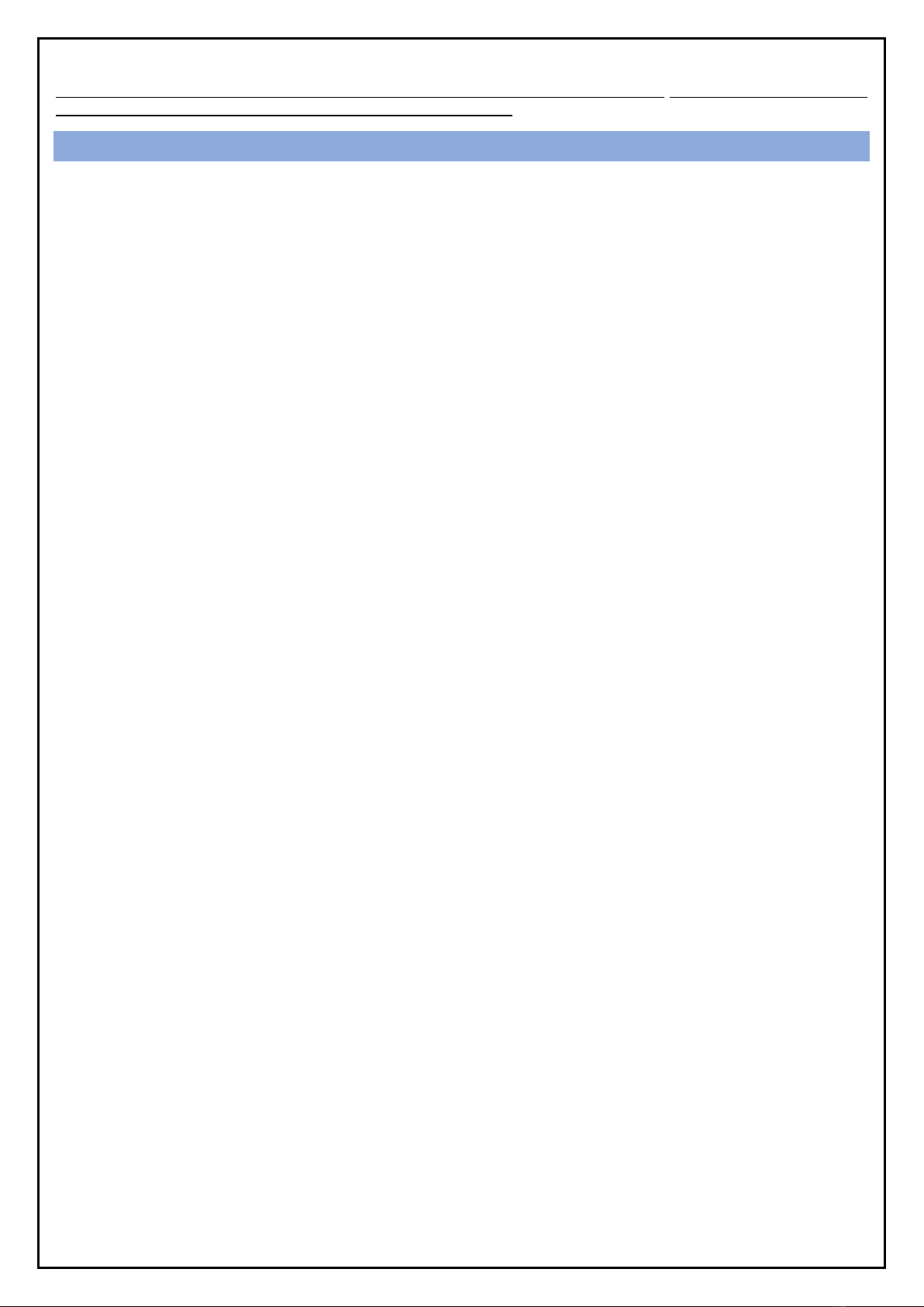
Nominal Diameter-End Connection: DN25xDN25 and DN25xDN40 threaded connection (modular connection on request)
Line Connection Directions: Tandem (180 degrees)
Product Weight: Approximately 5 kg
Suitable for following Fluids: Gas, Natural Gas, LPG and non-corrosive gases
Welding Process: Not available.
Material Standards:
For aluminum cast alloys: EN 1706
For brass materials: EN 12164 and EN 12165
For nodular cast iron with graphite: EN 1563
For elastomers: EN 549
Page 5of 32
Additional Features of the Model ERG-H5 Model;
High Pressure Safety Shut-Off Set Range “Wdo”: 30;5500 mbar
Up to 10 bar (LP=32;160, MP=155;500, HP=450;3000)
Up to 20 bar (LP=30;180, MP=40;450, HP=250;5500)
Low Pressure Safety Shut-Off Set Range “Wdu”: 6;3500 mbar
Up to 10 bar (LP=6;80 , MP=80;250 , HP=100;1500)
Up to 20 bar (LP=6;60 , MP=10;240 , HP=100;3500)
Safety Device Accuracy Class “AG”: ±%5 AG5, ±%10 AG10, ±%20 AG20, ±%30 AG30
Safety Device Action Type: quick action
Response Time: ≤2 seconds
Safety Device Functional Type: Class A
Safety Device Type: Combined safety device
Can the safety device be utilized as stand alone in the line?: No. It has to be integrated in the regulator at all times.
Gas Pressure Regulator Summary: The regulator, as its function, maintains the value of the controlled variable (outlet pressure-
Pds) within the tolerance range by reducing it to the desired/adjusted value, without being affected by disruptor variables (such
as flowrate and inlet pressure). The gas pressure regulator supports the devices installed after it to enable them working safely in
the gas line. The gas pressure regulator may have an air-released type evacuation system if requested during the order placement.
There may be a temporary gas release into the atmosphere from the regulator's auxiliary equipment. In this case, the necessary
measures regarding the gas to be discharged should be taken before installation.
Regulators have internal sensing. However, for higher capacity and better precision, it is also possible to connect an external line
for the regulator and safety shut-off.
The gas pressure regulator is not pilot controlled, does not have a controller feature, does not need a bypass unit to operate, is
not used as a backup inspection device and is spring driven.
The ERG-H5 Model gas pressure regulator has a high- and/or low-pressure gas safety shut-off device that is built in the same body,
i.e. placed in an additional combined way, and automatically cuts off the gas in the line and which activates when if the outlet
pressure raises and/or falls to undesired levels. This equipment is independent from the regulator in terms of function. Safety
shut-offs alone may be a stand-alone high-pressure safety shut-off kit, a stand-alone low-pressure safety shut-off, or both.
Combined Gas Safety Shut-Off Device (SSD) Summary: It is the device which automatically shuts down the gas flow completely if
the pressure that remains open and is in control under normal operating conditions exceeds the preset values (overpressure
and/or low pressure) (overpressure monitoring and/or low-pressure monitoring). If the outlet pressure increases or decreases to
undesired levels and exceeds the safety adjustment pressure, it automatically detects this situation and automatically cuts off the
gas on the line and remains closed until it is installed manually again. The gas is integrated into the pressure regulator.
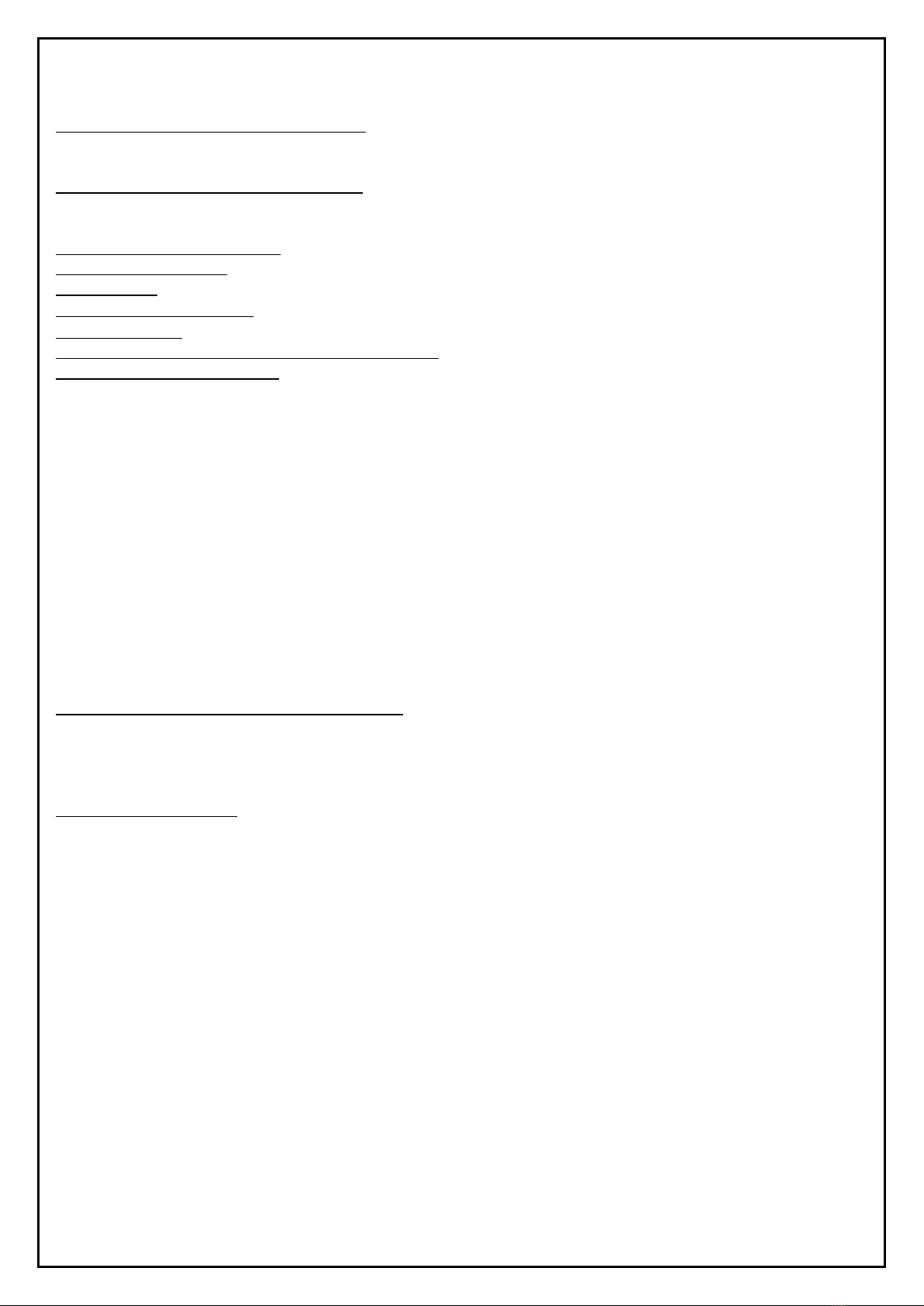
Discharge System Summary: The regulator and/or SSD can be produced with a relief valve. The safety valve continuously monitors
the outlet pressure and if it detects that the pressure level is higher than the nominal outlet pressure of the regulator and/or SSD,
it activates the gas and discharges it into the atmosphere. The safety valve has a limited discharge capacity. Usually the calibration
point is lower than the OPSO system. Under certain conditions such as gas expansion during hot weather seasons, the safety valve
is activated before OPSO shuts down the gas lines. It prevents random shutdown related to pressure increase on the outlet side.
The safety valve can be re-calibrated using appropriate tools.
Page 6of 32
Figure 1
Figure 2
4. MOUNTING
The process described in this information shall be carried out by technicians which are attested by gas approval bodies, duly
certified, authorized and experts in the field as well as by authorized companies-services-installers. The end user shall strictly not
carry out these operations. If the product will not be installed properly; incorrect or non-operation of the product or failures can
lead to loss of property, injury and loss of life. Our company will not be held responsible for applications carried out without
observing the manual.
Correctly determine and be sure of the characteristics of the product to be used before installation. Check the technical and
general information on the product and in this manual, compare it and make sure that the correct selection is made, especially
review the information on the label because it symbolizes the product itself. In case of any discrepancies between the information,
please contact the manufacturer without carrying out any operation.
A. BEFORE MOUNTING
Check auxiliary parts (gasket, seal, protection plug etc.) which may be on or in the product and the box, as well as the
documentation (manual, warning, label, certificate etc.) which have to be available with the product. In case of deficiencies or
failures please contact the manufacturer without carrying out any operation.
Make the necessary verifications and ensure that the comparisons to verify that the product to be mounted is in compliance with
the line specifications to be installed have been made (operating pressure range, fluid, flowrate, environmental conditions,
cleanness of the line and fluid, selection of the interconnectivity types and diameters, axis eccentricity in the line, appropriate line
and product dimensions etc.). In particular, the label on the product should be checked carefully and its suitability for operation
shall be confirmed.
Check and make sure that the inlet and outlet pipelines are aligned. In case of wet gases, necessary actions should be taken to prevent
water ingress and potential subsequent freezing. Confirm that the installation has been started in accordance with applicable technical
rules and laws. An inlet and outlet shut-off valve has to be mounted in the line which the product will be installed, being one each before
and after the product. To ensure protection against any pipe leakage, install manual gas shut-off devices (e.g. sphering valves etc.) in
REGULATION

Page 7of 32
front of and behind the product. While assembling to adjacent elements, pay attention that no oppression force shall be applied on the
housing and the mounting components (bolts, o-rings, sliders) must be suitable for the geometry and working conditions of the
equipment. No changes should be made on the product (drilling, grinding, soldering etc.). To avoid exceeding usage limits (PS, TS), make
sure that the inlet side is protected with a suitable device. Sufficient buffer volumes should be left at the line outlet after the device,
before installation. Confirm the accuracy of the bumper volume on the outlet side. The buffer volume should be 1/500 of the flowrate
at pressures up to 300 mbar and 1/1000 at higher pressures.
Check the accuracy of the flow direction. See the arrow mark on the body. Vent and relief lines, which may be required, must be made
in accordance with applicable rules and laws. In mountings made with non-condensing gases, the product can be assembled in any
position. In mountings with condensed gases such as LPG, the product should be placed at horizontal or vertical flow direction and the
outlet side should be downwards. Installation should be carried out with appropriate and approved seals. The sealed surface should be
clean and soft and new seals should be used at all times. Clean the inner side of the entire pipeline where the product will be installed
with compressed air before mounting the product and take precautions to ensure that these lines will not be contaminated again. Make
sure there are no particles left at any point on the line (dust, dirt, sawdust, foreign particles etc.). The fluid that will flow to the product
must be filtered before the product. A filter with ≤ 50 μm pore width should be placed at the inlet side. The regulator and SSD should be
kept away from direct sunlight and corrosive atmospheric effects.
The said pressure equipment must be installed in a non-seismic area and should not be exposed to fire and lightning strikes. For outdoor
installations, the regulator must be located away from vehicle traffic and positioned so that water, ice and other foreign substances do
not enter the spring case through the ventilation hole. Avoid placing the regulator under fringes or down pipes. Make sure that it is above
the potential snow level. Check the risk of explosive mixture in the pipeline. Make sure that all valves used before and after the product
which provide gas flow to the product are closed. Before starting the mounting, ensure that there is no pressure gas trapped in the line
where the product will be installed and between the line and the product, that the gas supply is turned off and that the possibility of
opening is completely prevented. Prevent explosive gas-air mixture. Avoid contact voltage and ignition of sparks in the product.
Necessary measures shall be taken to ensure that there is nosound and vibration caused by the line. Before installation, take appropriate
measures (clamping at the line side etc.) at the line inlet and outlet to reduce bending and torsion loads caused by pipes and shocks.
Attention should be paid to the relevant limitations in counter forces and moments caused by pipes and connections.
Make sure thatthe necessary dimensionsandareas are provided considering further operations (testing, maintenance, disassembly etc.).
In any case, check that the inlet pressure of the product shall be higher than the outlet pressure. Ensure that there are no diameter
narrowing and expansion over short distances at the inlet and outlet of the line on which the product will be mounted. Before installation,
it should be checked and ensured that the line pressure is within the inlet pressure range specified on the label on the product and that
the product capacity will not be exceeded during operation. It should be checked and ensured that there is no damage on the product
(visual and functional), that the product to be installed is suitable for the system to be used, that the pressure does not exceed the
maximum pressure level specified on the product label, that the product's dimensions fit with the line, that the installation place is at
adequate distance and under protection so that it will not be affected by sparks and electrical currents that may be caused by flammable
substances and devices.
Proceed with the installation process by taking necessary measures (such as protection box etc.) so that the product will not be exposed
to direct external environmental, corrosion and wearing conditions (sun, atmosphere, rain, snow, humidity, water, external chemicals
etc.) and to potential external damages and impacts. If the products are to be used in floor-mount applications, this should be indicated
while placing the order. In this case, products with properly coated surfaces should be used and appropriate measures should be taken
to prevent dirt, dust, dirt, liquid, etc. at the discharge part, if any, of the product. In addition, it should be ensured that the products shall
not be in form of embedded in full or in part into water, soil or liquids. If requested during order placing, the regulator may be equipped
with a breath line for leaking into the atmosphere as a result of a failure (such as diaphragm failure). If necessary (e.g., the use of the
product indoors etc.), the exhaust line must be connected to the breath line console of the product. This connection must be threaded
with minimum DN10 screws. The threaded screw adapter required for this connection shall be requested and used from the
manufacturer and shall be used accordingly. Gas pressure regulators and SSDs with discharge system; shall not be installed and operated
in closed areas and floor-mount applications without taking necessary measures for transmitting the gas to be discharged to the safe
zone (e.g. transmitting and mixing the gas to be discharged with a pipe of minimum DN 10 to external atmospheric conditions, etc.).
Before installing the product on the line; perform a general check for the pressure and sealing of the line and system.
B. DURING MOUNTING
Manually remove the inlet-outlet connection protection plugs, if any. If the product is equipped with modular connection additionally,
manually and carefully place the inlet and outlet seals which are shipped in the product box to the inlet and outlet connection nozzles
(always use certified and new seals). Set the flow direction of the product by showing the arrow outlet side and gas flow direction in the
product body and ensure that the joint components to be used during installation shall comply with the regulations. Install the product
only in accordance with applicable legislations and local regulations, obtaining the necessary approvals, if necessary. Do not install the
product outdoors without mounting the product into a housing and taking required protective measures. The lifting equipment being
used must be suitable for loads to be lifted. While connecting the product to the line no overload, force and impact shall be applied.

Page 8of 32
While connecting the product to the line; place it in such way that the product shall not block the front of the sensing line. Pay attention
to the specified distance of the measuring point for the sensing line. While connecting the product to the line; use appropriate wrenches
for tightening inlet and outlet connections and make sure that no excessive load, force and impact is applied and that external leakage
is prevented. Pipe connections should always be welded to the upper part of the pipe, and the hole in the pipe should not show any burrs
or protrusions inwards. Ensure that there is no pressure gas trapped in the line where the product will be installed and between the line
and the product, that the gas supply is turned off and that the possibility of opening is completely prevented. After tightening, make the
controls that the connections are fully seated in the sockets and there are no cracks, breakages, etc., mechanical problems and
deformations in the connections and in the product and that no mechanical stress caused by the line, pipe and connection has occurred.
If connection components which are larger than the connection diameter on the body of the product are installed in the inlet and outlet
of the product for assembly, forces and moments exceeding the values required by the main connection diameter on the body should
not be applied and limitations should not be exceeded.
While screwing the product on the line, make sure that the pipe thread is not too long in order to prevent damage on the body. If the
product is modularly flanged; make sure that the inlet and outlet counter flanges are perfectly coaxial and parallel in order to avoid
unnecessary mechanical pressure on the product body. Also calculate the space required to place the seal. As the product may be
disassembled from the installation for testing, repair, maintenance, replacement and similar purposes, use a gland or ball valves at the
product inlet and outlet. Connect the product to the line without causing mechanical stress. It should be remembered that excessive
loads to be applied to the body may lead to cracks. For these reasons, assemble with wrenches. For products with flanges, follow the
mounting torques shown in chart 2. For tightening operations, make available single or double calibrated torque wrenches or other
controlled locking tools. After tightening, make the controls that the connections are fully seated in the sockets and there are no cracks,
breakages, etc., mechanical problems and deformations in the connections and in the product and that no mechanical stress caused by
the line, pipe and connection has occurred.
The necessary gaps and spaces should be left around the product and between the wall and the product by taking the outer dimensions
of the product as reference, in order to enable access to the product’s components, perform the necessary operations and carry out
testing. If the product is accessible to unauthorized persons, provide protection against impact or accidental contact. During installation,
make sure that the gas in front of the product is turned off. Close the gas cutting valves at the line inlet and outlet. Make sure there are
no gas flows. While mounting the product on the line; connection shall be in the direction of the arrow indicated on the product. The
arrow on the product shall be mounted in such way that the outlet side shall indicate the user, that means it shall show the gas flow
direction. By this, the flow will be from the network to the user.
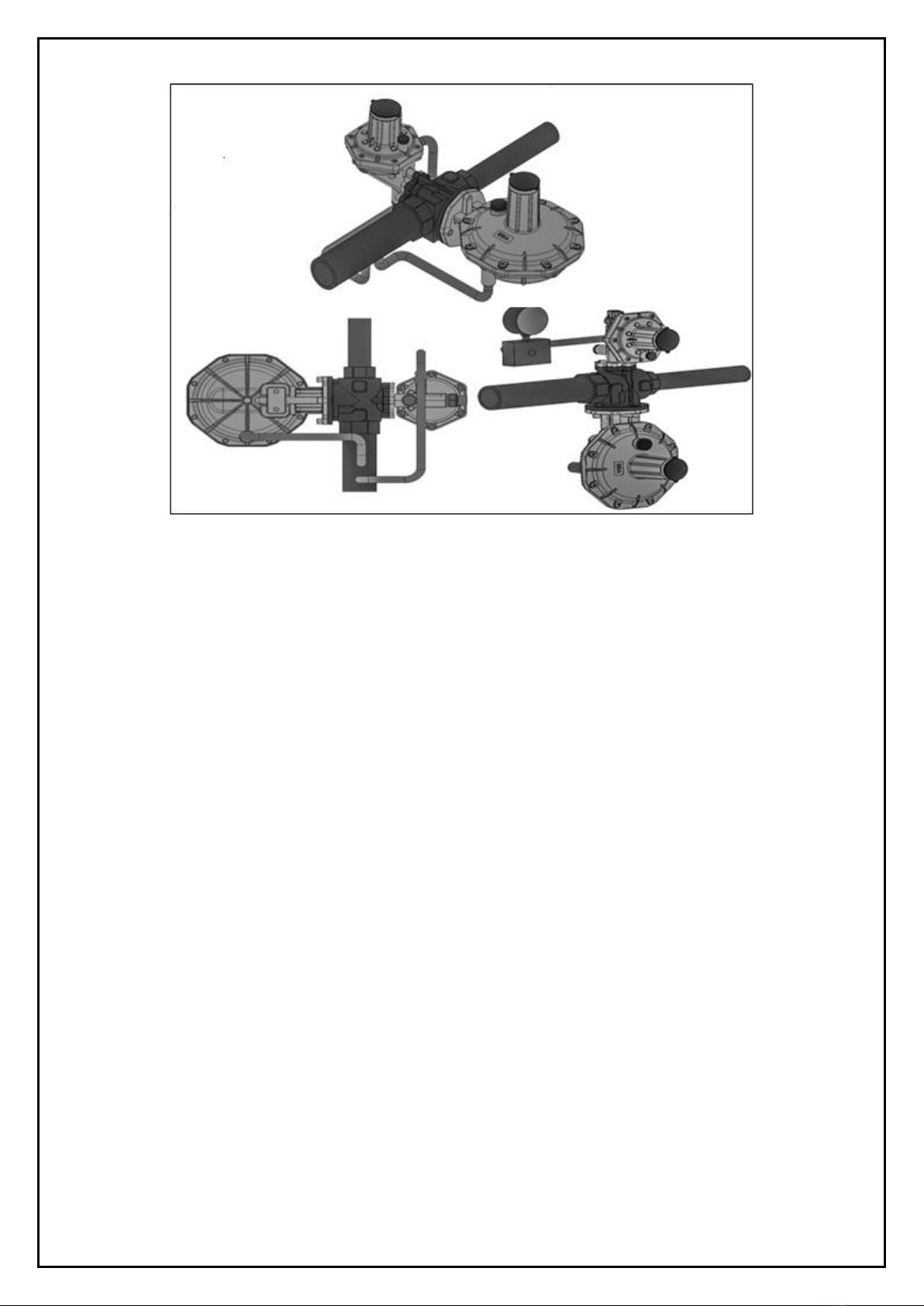
- Install the product in horizontal or vertical position with a tolerance of ±5oC at the appropriate mounting position as shown in figure 3.
However, it should be preferred to install in such way that the cover shall be vertical with an upwards direction. The mounting position
for dry gases may be vertical or horizontal provided that the outlet pressure regulation part shall not be downwards and mounting
position for LPG shall in such way that the regulator’s outlet side shall be downwards.
Figure 3

Page 9of 32
The sensing line for regulation mounted on the outlet of the product and sensory line in models with SSD should be completely exempted
from any obstacles or deformations. Necessary measures should be taken for this. Manually place the inlet and outlet seals for product
assembly which are shipped in the box on inlet and outlet connection nozzles properly (always use certified and new seals). It also shall
be ensured that the seals shall show no defects that will impair the sealing properties. When connecting the product to the line; product
inlet and outlet must be connected to the relevant pipeline with nipples or moving glands, if any.
If the product has threaded connection; assemble together with appropriate seals by screwing to the line by pipes and/or fitting
components with appropriate threads being attached to the connection. During screwing, do not use any part of the product as an
apparatus to support the screwing operation. Use appropriate equipment for assembly. Use chip-free, newly reamed and threaded pipes.
If the product is provided with flanged connection or modularly; it shall have the same dimensions at the inlet and outlet and face-to-
face dimensions must comply with national laws, regulations or relevant standards. Install the product by flanging together with the
necessary and appropriate seals, screws and nuts to the installation with pipes which is compatible with the line which has the same
flange connection. The seals should be centered between the flanges and it should be ensured that there are no defects in the seals
which will disrupt the sealing properties. If there is too much space between the seals after placing, do not try to reduce this space by
tightening the bolts too much. Make sure that the arrow direction in the body of the product is compatible with the line. Take the
necessary measures to avoid any damages on the flanges during the tightening process. Be careful not to damage the seal when
tightening. Gradually tighten nuts or bolts in a "diagonal" pattern (chart 2). Gradually tighten them with increased torque (chart 2).
Tighten each nut one by one and tighten again clockwise at least once until maximum torque is achieved.
C. AFTER MOUNTING
Confirm that the installation has been carried out in accordance with applicable technical rules and laws. After completion of the
mounting process, check and be sure that that the product is not reverse-mounted. After the product is assembled, carry out the
necessary checks. Ensure that the product impermeability is provided (example; external impermeability, visual control).
Gas Inlet, Impermeability Control and Adjustment:
- The product pressurizing should be carried out quite slowly.
In order to protect equipment from damage, the following procedures should never be carried out:
- Pressurize the system with the valve at the outlet side
- Lowering/discharging the pressure of the system with the valve at the inlet side
- To ensure that there is no leak by a foam test applied at low pressure
- The regulator and all other apparatus are delivered being adjusted to the desired set value. The adjusted value of the spring may
vary due to various reasons (shock during transportation etc.). It is recommended to adjust the set values according to the label values.
- Before commissioning the regulator, it should be ensured that all on/off valves (in, out, all kinds of by-pass) are closed and that the
gas is at a temperature that does not cause any deterioration.
5. INSTALLATION, COMMISSIONING, OPERATION
A. BEFORE
Before installation, carefully review, keep with you and fully follow the instructions in this manual and the information on the label
on the product. If you think there is incomplete and incorrect information, contact the manufacturer and do not carry out any
operation.
Before installation, check and provide that all users and persons at the outlet side have not made any use. Make the necessary
warnings so that users do not make any use. The main gas supply must be turned off before starting the installation. Before
installing the product; ensure that the product is mounted in the line correctly. During installation; prevent ingress of particles
such as dirt, rust, dust etc. to the product and take permanent measures. The non removal of residues will cause damage or
incorrect performance.
During commissioning; unauthorized personnel should be strictly kept away and the area with restricted access should be properly
marked (signs, barriers, etc.). During commissioning; in the event that flammable or harmful gases are released into the
atmosphere, the risks identified by any discharge should be assessed. During installation; consider the risk of an explosive mixture
(gas/air) which may form in the pipes. Take the necessary measures. Make sure that all breath and/or exhaust lines in the product
are not clogged. Then take the further necessary measures to prevent these lines from being blocked. Do not install any caps such
as blind plug to these lines which may prevent the gas outlet.

Page 10 of 32
Do not change the factory settings of the product. The factory settings are adjusted according to the desired values in the order
specification and are indicated on the product label. Adjustment devices are sealed if requested in the order specification. Such sealing
is recommended by the manufacturer. Start operating the product only if all protective equipment is fully operative. If there is an angled
line and/or pipeline supports are insufficient, do not apply the weight of the line on the product only due to such reasons at any time or
for any reason. Take the necessary measures for this status. Before starting the gas flow, check the pipeline for impermeability and make
sure it is sealed.
B. DURING
- INSTALLATION PROCESS FOR MODELS WITH SSD:
1- Partially open the outlet valve in the line, partially open the outlet vent valve,
2- Slightly, slowly and gradually open the inlet valve, means the gas supply valve in the line, check that the input pressure is correct.
3- Manually remove "SR SHUT OFF SAFETY PLUG NO. 60” by turning counter clockwise,
4- Pull the "H5 OPSO INSTALLING LEVER No. 57" slowly and gradually towards yourself without applying excessive load, force and
impact (Figure 4) (thus allowing the outlet side to be filled with gas.),
5- When the output pressure reaches the setting value, pull the "H5 OPSO INSTALL LEVER No. 57" to yourself a little more and hold it
until it remains in the pulled position (until the slam shut is installed), verify that the output pressure is balanced.
6- Check and verify that the "H5 OPSO INSTALL LEVER No. 57" remains pulled, that there is gas flow at the outlet side, that the released
gas is mixed in the atmosphere if the product is equipped with a discharge system, and check that outlet and gas impermeability is
achieved by appropriate methods (foam, detector etc.).
7- Wait until the output pressure reaches the desired value. If necessary, set the output pressure value with the "SR REGULATION
ADJUSTMENT SCREW No. 2".
8- Close the output vent valve.
9- Gently open the cut-off valve at the entrance.
10- Thus, the product will be installed.
11- Repeat the steps if the installation is not realized.
12- After completion of the installation, attach the "SR SHUT OFF SAFETY COVER No.60" again (installation process schematic display
figure 4).
13- If you have difficulty in pulling the "H5 OPSO INSTALLATION ARM No. 57" during installation or if you encounter the closure of the
"H5 OPSO INSTALLATION ARM No. 57" because the output pressure comes ahs reached the safety adjustment pressure, then take all
necessary safety measures and you can carry out operations such as removing the "SR BREATH LINE NO. 6", if any, opening the input
valve not completely but gradually in parts, allowing a small amount of gas release from the test nipple at the outlet line, if available.
14- After the operations, manually replace the parts you have used ("SR BREATH LINE No.6 ", "SR SHUT OFF SAFETY COVER No. 60",
test nipple etc.).
15- Inform all gas users about the use of gas.
- INSTALLATION PROCESS FOR MODELS WITHOUT SSD:
1- Partially open the output valve in the line,
2- Gently open the inlet valve in the line, i.e. gas supply, check that the input pressure is correct.
3- When the input valve that will feeds the product is opened, the gas flow will automatically start to the outlet, wait a few seconds,
4- Verify that there is gas flow at the output side, so the product will be installed.
5- If the installation is not realized contact the manufacturer.
Figure 4
Page 11 of 32
C. AFTER
If the setup process does not occur or f you encounter different problems afterwards; contact the manufacturer without carrying out
any operation.
The setup shall not affect the function of other components.
Under closed conditions or inside, the leaked gas can accumulate and create danger of explosion. In such cases, the ventilation hole
should be connected by piping from the product to outdoors (atmosphere).
If the product is exposed to excessive pressure, it should be checked for any damage that may have occurred. If the overpressure is high
enough to damage the product, some kind of external overpressure protection must be provided.
The product’s operation under the limits specified in this manual and the product label: This does not prevent damage caused by external
sources or residues in the pipeline. The inlet must be protected with appropriate equipment to avoid exceeding the permitted limits (PS,
TS).
When designing a decompressing station, carry out an analysis that takes into account the impact of wind, snow and temperature to
prevent unnecessary load and equipment from moving towards the flanges and take the necessary measures according to this analysis.
If necessary, a support can be used under the pipe and regulator/SSD body to prevent excessive pressure on the regulator/SSD.
The installed product shall be adequately protected from vehicle traffic and damage from other external sources.
Do not install the product where excessive water accumulation or ice formation can occur. In some installations, such as in areas with
heavy snowfall, a cap or enclosure may be required to protect the product from the snow load and to prevent freezing caused by air
discharge. The necessary measures should be taken considering the aforementioned situations.
Depending on the temperature during and after the installation process or during mid seasons, instant gas output from the product’s
relief section may occur which is normal. It is important that such gas output in question shall not continue; if it continues it can be
considered that there is a failure in the product. In such a case, the products use shall be discontinued and the authorized
persons/organizations should be contacted immediately.
If the product is closed for various reasons during operation, the inlet and outlet valve should be closed, the problem should be detected
and the product shall be re-installed according to the aforementioned rules.
If the product is equipped with a discharge system; gas discharge to the atmosphere shall not be performed under any circumstances;
however, there may be temporary discharges from auxiliary equipment. If there is a continuous discharge contact the authorized
person/institutions immediately.
If the product is shut down for various reasons during operation:
1- The inlet and outlet valve should be closed, the problem should be detected and re-installed according to the aforementioned rules.
2- The output pressure may increase and the product’s high pressure safety shut-off device may close which will lead to gas cut-off,
depending on contaminated gas and foreign matters in the line, which will cause pressure-capacity changes due internal leakage,
abrupt stop of the combi boiler, boiler etc., breathing line clogging, product failures etc. In this case, the reinstallation process has to be
repeated.
3- If the output pressure of the product drops excessively for various reasons during operation and reaches the adjusted safety
pressure, the low-pressure safety shut-off system activates and the gas flow may close. In this case, the reinstallation process has to be
repeated.
- TESTS
After installation, output pressure, high- and/or low-pressure closing pressures and internal impermeability, external impermeability and
the capacity should be checked. While performing these procedures, take all necessary measures to ensure that the discharged gas
generated from the product or the external leakage shall not a hazardous atmosphere and do not operate indoors.
Note: In no case should operations be performed which lead to pressure income or pressure flow of more then 20 bars to the inlet
connection nozzle and body of the product or to pressure income or pressure flow of more then 6 bars to the housings where the
product’s outlet pressure adjustments are made and such situations shall be strictly prevented.
To examine the pressure values; carry out this procedure with a calibrated manometer mounted on minimum 5xDN in the pipeline at
the outlet side of the product. DN is the value that depends on the diameter at the output of the product.
Page 12 of 32
- OUTLET PRESSURE, LOCKING PRESS, INTERNAL IMPERMEABILITY AND RELIEF PRESSURE TESTS
1- Connect the related pressure gauge and pressure source to the appropriate test valve located on the output line of the product in a
firm and sealed manner.
2- Measure the output pressure when there is gas consumption in the line and check its conformity within the tolerances.
3- Close the output valve (Q=0 m3/h) at the outlet of the product and wait for a while, then check that the output pressure is in
balance and its value is within the tolerances.
4- Slowly increase the pressure on the pressure source, observe the value in the manometer and verify that the product is discharging
at the declared discharge value of the product. Gas output to the outside is an indication that the valve has been activated.
- SAFETY SHUT-OFF PRESSURES TEST
1- Temporarily close the relief part of the product (do not forget to open it after testing.),
2- For the product which has reached the relief pressure; slowly increase the pressure on the pressure source up to the high-pressure
safety shut-off adjustment value and check that the “H5 OPSO SET-UP LEVER No. 57”is closed. If it is closed this means that the values
are conforming,
3- Open the discharge valve and allow it to continue its functioning,
4- Then re-dry the product and close the inlet valve, reduce the pressure on the product and also reduce the pressure at the pressure
source below the output pressure. Continue to reduce the pressure until the slam shut reaches the minimum closing value and is
activated. Verify that the product automatically shuts itself off,
5- Remove the pressure source, close the test valves,
6- Check the line and the product for external leaks,
7- Re-dry the product in accordance with the rules mentioned in this instruction,
8- Monitor the output pressure from the manometer and bring it to the set value and make sure that the slam shut remains installed at
the desired value.
- OUTER LEAKAGE TEST
1- Set the inlet pressure to 1,1xPS bar.
2- Apply an appropriate leakage detection spray.
3- If any foam formation occurs this means an outer leakage.
- LOCKING PRESSURE AND INTERNAL IMPERMEABILITY
1- Turn on the inlet valve and set it up to Pumax pressure and observe its accuracy in the manometer,
2- Close the output valve (Q=0 m3/h) at the outlet of the product to ensure that there is no consumption on the output side. Wait a
while and check that the output pressure value read on the manometer is balanced and its value is within tolerances. Observe that
fluctuations are minimal. If there is any nonconformity, the product has failed the test.
Note: In no case should operations be performed to cause pressure at the product’s inlet connection nozzle which exceeds the PS value
on the product label and any operations in the upper cover section where the products’ outlet pressures are regulated which cause
pressure or gas flow over 8 bars; this situation should strictly not be allowed to occur.
6. SETTINGS
A. BEFORE
Before adjusting, make sure that gas in front of and behind the product is turned off.
Please keep the manual and the label on the product with you before adjusting. Perform the procedures according to the information in
this manual.
Before setting; make sure that the existing springs are those springs that can provide the desired values. Check this from the springs
chart. Please contact the manufacturer if you are not sure.
Models with SSD: regulation spring, regulation discharge spring, high pressure shut-off spring, low pressure shut-off spring,
Models without SSD: regulation spring, regulation discharge spring.
If you observe any nonconformity in the springs (incorrect spring, corrosion, etc.) before adjusting, please request those from the
manufacturer without performing any operation.
Page 13 of 32
B. DURING
The spring used in products is designed to provide desired output pressure intervals. For output pressures outside the specified range, a
spring change will be required. These springs must be supplied from the manufacturer.
- If required for various reasons, the output pressure of the product and safety closure pressure settings, if any, should be made as
follows:
1- The settings shall not be changed at a rate more than ± 10% and/or outside the limits specified on the label.
2- Seals on the related sections of the product, if any, shall be removed.
3- While adjusting the pressure, the adjustment mechanisms and springs should not be compressed, bent and forced excessively.
4- To see the values of the settings, connect the pressure gauge or manometer to a suitable test valve located between the product
and the output pipe and monitor the pressure by consuming gas within the appropriate capacity range.
5- For all adjustments to be made, pressure increase is achieved in clockwise rotations and pressure decrease in reverse rotations.
6- If there is an SSD, an increase in safety pressures should be ensured when adjusted output pressures are increased and a decrease in
safety pressures should be ensured when reduced.
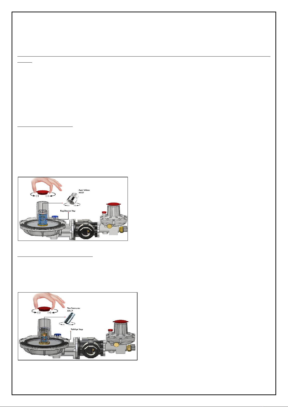
- OUTLET PRESSURE SETTING:
1- Remove the relevant seal, if any,
2- Remove the "SR TOP COVER PLUG No. 1" by manually rotating it counterclockwise,
3- Turn the "SR REGULATION ADJUSTMENT SCREW No. 2" in the appropriate direction with the appropriate hexagonal wrench, (turning
counter clockwise reduces the outlet pressure; turning clockwise increases the output pressure.),
4- Mark the adjustment pressure being set,
5- After the procedures; Manually replace "SR TOP COVER PLUG No. 1" to its initial position.
Figure 5
- RELIEF (Regulation) PRESSURE SETTING
1- Remove the relevant seal, if any,
2- Remove the "SR TOP COVER PLUG No. 1" by manually rotating it counterclockwise,
3- Turn it in the appropriate direction with the hexagonal wrench suitable for "H1 TEMPER NUT No. 9",
4- Mark the adjustment pressure being set,
5- After the procedures; manually replace the "SR TOP COVER PLUG No. 1" to its initial position.
Figure 6

Page 14 of 32
- HIGH SAFETY PRESSURE SETTING:
1- Remove the relevant seal, if any,
2- Remove the "SR TOP COVER PLUG No. 81" by manually rotating it counterclockwise,
3- Turn the "80 SR REGULATION ADJUSTMENT SCREW" in the appropriate direction with the appropriate hexagonal wrench,
4- Mark the adjustment pressure being set,
5- After the procedures; manually replace "SR TOP COVER PLUG 81" to its initial position.
Figure 7
- LOW SAFETY PRESSURE SETTING:
1- Remove the relevant seal, if any,
2- Remove the "SR TOP COVER PLUGI No. 81" by manually rotating it counterclockwise,
3- Turn the "H1 Min ADJUSTMENT SCREW No. 76" in the appropriate direction with the appropriate hexagonal wrench,
4- Mark the adjustment pressure being set,
5- After the procedures; Manually replace "SSD TOP COVER TAPASI 81" to its initial position.
Figure 8
C. AFTER
After the adjustment changes check, by appropriate methods, that technical characteristics and limits specified in this manual and on
the product have not been exceeded. All aforementioned tests should be repeated and it shall be ensured that the results are in
conformity.
It is recommended to seal the adjustment devices so that the settings are not changed after the relevant pressure settings have been
made or if the products will be used in the field. The seal contained in the box, if any, can be used for this process.
Test the set values 3 times to make sure they are set correctly. The testing methods should not disrupt the functionality of the product.
To examine the pressure values; perform this process with a calibrated manometer mounted on at least 5xDN in the pipeline at the outlet
side of the product. DN is the value that depends on the diameter at the outlet of the product.
If the product is assembled in different positions, check the output, discharge, OPSO, UPSO, SSD discharge pressures and perform the
test 3 times to ensure that they are at the correct setting. To examine the pressure values; perform this process with a calibrated
manometer mounted on at least 5xDN in the pipeline at the outlet side of the product. DN is the value that depends on the diameter at
the outlet of the product.

Page 15 of 32
7. PERIODICAL MAINTENANCE AND INSPECTION
A. BEFORE
Periodic maintenance-inspection is recommended for the intact and safe operation of the product.
For all operations, full compliance with the rules in this manual must be ensured. This manual should always be with you before, during
and after periodic maintenance-inspection and all rules in this manual should be followed. If you think there is any incomplete and
incorrect information, contact the manufacturer and do not carry out any further operation.
No repairs on the product should be carried out by the user. All repair operations should be carried out by authorized services and
personnel. Users or non-authorized persons should not intervene in the product or in the line in case of any malfunction. The parts that
may needed to be disassembled for repair in the product can be removed and installed with normal hand tools and are formed sin such
way that they are not installed incorrectly. To prevent personal injuries or damage to equipment, do not perform any maintenance or
disassembly without separating the product from the system pressure and draining all internal pressure, as described in the "Shut-Off"
section. It is important to ensure that the product is isolated from the inlet and outlet pressure and that the pressure between the
product and outlet valve section of the line has been discharged. Prevent explosive gas-air mixture: constantly control the air of the room
for gas leakage with a suitable gas concentration measurement device.
The plant shall be equipped with discharge devices and systems to discharge the pressure and fluid from the plant before any inspection
and maintenance operations.
The maintenance process is closely associated with the quality of transporting of gas (particles, humidity, gasoline, corrosive substances)
and the efficiency of filtering.
In any case, make sure that there is no pressurized gas in the product before performing any maintenance operation.
The periodic maintenance-inspection intervals should not exceed the intervals specified by the gas organization or the related legislation.
The maintenance time shall be adjusted according to the working conditions.
If not determined by rules, the time period of preventive maintenance depends on the following conditions:
1- The quality of gas transportation
2- Cleaning and protection of the pipeline before the product: in general, after commissioning, maintenance may be required very
often, since the pipeline is not clean enough.
3- The level of reliability required by the regulatory system
Perform maintenance of the product’s parts with an "EITHER CLEAN OR REPLACE" approach.
B. DURING
In any case, do not apply abrupt discharge to clean the line after the product or to carry out maintenance-repair operations on the
product.
Disassemble the product from the line in accordance with the disassembly rules specified in this manual. Before starting the process,
ensure that the gas in front of and behind the product is turned off. Make sure that the fasteners (screws and/or bolts-nuts) in the
product are screwed and unscrewed with the specified torques. For this purpose, use a calibrated device and keep it with you. Install the
covers exactly in the same place again using the same screws, without applying any contraction and straining on the screws and by
reciprocal tightening without applying excessive force so that the holes overlap completely and make sure that they do not remain loose
and are not exposed to any mechanical damage. If there is any paint-lacquer etc. on the fasteners, do not perform any process and
contact the manufacturer first.
If necessary, do not disassemble the parts inside the enclosures which you have removed separately, hold the enclosures as a group with
the parts inside clean them slowly with a clean cloth.
If a problem will be identified during the periodic maintenance and inspection, necessary actions shall be taken according to the rules
described in the failures chapter.
Maintenance intervals depend on system-specific operating and ambient conditions, gas quality, the condition of pipelines, etc. The
maintenance intervals should be determined by the operator of the system in a system-specific manner. The inspection/control and
replacement frequencies depend on the severity of the terms of service and applicable national laws, regulations, standards and
directive/recommendations. We recommend function control on a monthly basis and maintenance on an annual basis to ensure that the
system shall remain operative. At worst, function control on an annual basis and maintenance on a biennially basis may be preferred.
The pressure equipment directive (PED) and the energy performance of buildings directive (EPBD) stipulate a regular control of heat
generators to ensure high efficiency and therefore low emissions to the environment in long terms.

Page 16 of 32
Regarding spare parts; any parts which are not original and are not coming from our company except those parts provided with the
product and the box shall not be used. If necessary, contact only the manufacturer for the supply of spare parts. The necessary spare
parts kits must be available. For mounting and dismounting, the appropriate tool kits must be available.
Manually remove the seal on the input connection side and the output seal on the output connection side and clean them properly,
replace them, if necessary.
Review the measures having been taken for hazards related to the release of flammable or harmful gases to the atmosphere.
Always use new seals after part replacement or conversion.
Do not clean with cleaners containing alcohol or solvents.
Reversely apply the maintenance procedures stated below and reassemble this section.
- SPRING MAINTENANCE:
Output Pressure Adjustment Spring:
1- Remove the "SR UPPER COVER PLUG No. 1" by manually rotating it counterclockwise,
2- Flip "SR REGULATION ADJUSTMENT SCREW No. 2" with the appropriate hexagonal wrench,
3- Remove "H5 REGULATION SPRING No. 3" with your hand, be careful if there is an "OVER-SPRING WASHER",
4- Place the spring supplied from the manufacturer properly and without forcing,
4- Place the "SR REGULATION ADJUSTMENT SCREW No. 2" with the appropriate hexagonal wrench to its initial position,
5- Manually assemble the "SR UPPER COVER PLUG No. 1" by rotating clockwise,
6- Cary out the required processes for the recycling or disposal of the old spring.
Evacuation (regulation) Adjustment Spring:
1- Remove "SR TOP COVER PLUG No. 1" by manually rotating it counterclockwise,
2- Turn the "H1 TEMPER NUT No. 9" with the appropriate hexagonal wrench,
3- Remove the "H1 TEMPER SPRING No. 10" with your hand, be careful if there is an "OVER-SPRING WASHER",
4- Place the spring supplied from the manufacturer properly and without forcing,
4- Place the "H1 TEMPER NUT No. 9" with the appropriate hexagonal wrench to its initial position,
5- Manually assemble the "SR UPPER COVER PLUG No. 1" by rotating clockwise,
6- Cary out the required processes for the recycling or disposal of the old spring.
High Pressure Shut-Off Safety Spring
1- Remove “SR TOP COVER PLUG No. 81”by manually rotating it counterclockwise,
2- Remove “SR REGULATION ADJUSTMENT SCREW No. 80” by turning it with the appropriate hexagonal wrench,
3- Remove “H5 OPSO SPRING No. 77”with your hand, be careful if there is an "OVER-SPRING WASHER",
4- Place the spring supplied from the manufacturer properly and without forcing,
4- Rotate the “SR REGULATION ADJUSTMENT VIDEO no.80” with the appropriate hexagonal wrench to its initial position,
5- Manually assemble the "81 SR TOP COVER PLUG" by rotating clockwise,
6- Cary out the required processes for the recycling or disposal of the old spring.
Low Pressure Shut-Off Safety Spring
1- Remove the “SR TOP COVER PLUG no. 81”by manually rotating it counterclockwise,
2- Remove the "H1 MN ADJUSTMENT SCREW No. 76" with the appropriate hexagonal wrench,
3- Remove the “H5 OPSO MIN SPRING No. 75”with your hand, be careful if there is an "OVER-SPRING WASHER",
4- Place the spring supplied from the manufacturer properly and without forcing,
4- Rotate the “H1 MIN ADJUSTMEN SCREW No. 76” with the appropriate hexagonal wrench to its initial position,
5- Manually assemble the "81 SR TOP COVER PLUG" by rotating clockwise,
6- Cary out the required processes for the recycling or disposal of the old spring.
- REGULATION SECTION MEMBRANE MAINTENANCE-REPLACEMENT
1- Duly unscrew the screws "M5x20 THB SCREW" of the "H5 REGULATION COVER No. 8". By this, remove the cover together with its
inner parts from the "H5 REGULATORY BODY No. 22",
2- Remove the "H1 TEMPER NUT No. 9" with the appropriate hexagonal wrench,
3- Remover the "H1 TEMPER SPRING NO. 10", "H1 REGULATION BUMPER NUT No. 11", "H1 SPRING BOTTOM WASHER No. 12", "H5 LP
REGULATORY BUMPER No. 13".

Page 17 of 32
4- Change "H5 LP REGULATION DIAPHRAGM No. 14".
5- Check the o-rings and/or gaskets which are seen during the assembly/disassembly works on the product. If damage in the -orings
and/or gaskets are observed such as tearing, wear, deformation etc., request the same original o-rings/gaskets from the manufacturer.
Upon receipt, replace the deformed o-rings/gaskets with new ones and assemble the product. In this way, you will have made the
replacement of "O-RING-GASKET". Carry out the appropriate recycling or disposal process for the old o-rings/gaskets.
6- Assemble the product by performing all operations in reverse order.
7- Check the accuracy of the product with tests.
- SSD SECTION MEMBRANE MAINTENANCE-REPLACEMENT
1- Duly unscrew the screws "M5x20 THB SCREW" of the “H5 OPSO COVER No. 72”. By this, remove the cover together with its inner
parts from the "H5 OPSO BODY No. 55".
2- Remove the "H5 UPSO BUMPER No. 71".
3- Remove the "M12 NUT No. 70" with the appropriate wrench.
4 - Remove “H5 LP REGULATORY BUFFER No. 69”.
5- Replace the "H5 LP REGULATION DIAPHRAGM NO. 68".
6- Check the o-rings and/or gaskets which are seen during the assembly/disassembly works on the product. If damage in the -orings
and/or gaskets are observed such as tearing, wear, deformation etc., request the same original o-rings/gaskets from the manufacturer.
Upon receipt, replace the deformed o-rings/gaskets with new ones and assemble the product. In this way, you will have made the
replacement of "O-RING-GASKET". Carry out the appropriate recycling or disposal process for the old o-rings/gaskets.
6- Assemble the product by performing all operations in reverse order.
7- Check the accuracy of the product with tests.
C. AFTER
Assemble and install the product which its maintenance process has been completed in accordance with this manual. Make sure that the
threaded or flanged connection between the product and the line is made correctly and is tight. Check and ensure that all accessories
and apparatus (seal, plug, cover, filter, etc.) are attached to the product. In all cases, make sure that nobody is present indoors in any
situation which leads to gas release from the product or the line to the atmosphere, that no hazardous atmosphere is and/or will be
formed and that all necessary lines are opened to the atmosphere. After maintenance, sort any idle and waste parts according to the
disposal or recycling methods in accordance with the laws and regulations.
Check and ensure that there are no external leaks in any area of the product with appropriate methods (detector, foam etc.). During and
after the periodical maintenance and inspection procedures, attention shall be paid that particles such as dirt, rust, dust, sawdust, etc.
do not enter the section where there is clean gas. Check that there is no sound or vibration in the product. After the procedures, check
that the technical characteristics and limits mentioned in this manual and on the product are not exceeded using appropriate methods.
Perform the test operations described in the installation section in this manual by taking all relevant security measures. If any problem
is identified during the periodical maintenance and inspection, necessary actions can be taken according to the rules described in the
failures chapter.
8. DECOMMISSION, DISASSEMBLY AND REPLACEMENT
Follow all the rules set forth in this manual before, during and after all disassembly and replacement works and take the necessary
actions.
A. BEFORE
Before and during disassembly and replacement processes, ensure that there is no pressurized gas trapped between the line and the
product, that the gas supply is turned off and that it is completely prevented from any potential opening.
B. DURING
Close the inlet and outlet valves on the line at the front and back of the product.
Safely and gradually discharge the trapped gas between the line and the product from the section between the product and the outlet
valve in accordance with the legislation.
Remove the inlet and outlet connections of the product from the line by rotating them with an appropriate wrench and without applying
any overload and force.
C. AFTER
If the product will be replaced with a new one, assemble and install the new product according to this manual.

Page 18 of 32
9. DIMENSIONS, CONNECTIONS AND PARTS
The dimensions are in mm.
Figure 9
Regulation Discharge No. 1: G1/4 ISO 228
SSD Discharge No.2: G1/8 ISO 228
SSD Sensing Line No.3: GE12-1/4, For Pipes: 12 X 1.5
Regulation Sensing Line No.4: GE12-1/4, For Pipes: 12 X 1.5
Figure 10
Display of the External Sensing Connection
Page 19 of 32
Figure 11

Page 20 of 32
This manual suits for next models
1
Table of contents
Other ESKA Controllers manuals


