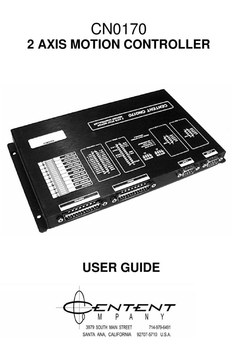
CENTENT CN0170 User manual

HARDWARE MANUAL
CN0170
TWO AXIS
MOTION CONTROLLER
3879 SOUTH MAIN STREET 714-979-6491
SANTAANA, CALIFORNIA 92707-5710 U.S.A.
0 M P A N Y


This manual contains information for installing and operating the
following Centent Company product:
•CN0170 Motion Controller
Centent and the Centent Company logo are trademarks of Centent
Company. Other trademarks, tradenames, and service marks owned
or registered by any other company and used in this manual are the
property of their respective companies.
Copyright ©2019 Centent Company
3879 South Main Street
Santa Ana, CA 97207
All Rights Reserved

CENTENT MOTION CONTROLLER
CONTENTS
Connectors ......................................................................................... 1
X-Axis, Y-Axis Connector.................................................................... 2
Step Output..................................................................................... 2
Dir Output ....................................................................................... 4
ISet Output...................................................................................... 5
+5VDC ............................................................................................ 6
Gnd................................................................................................. 6
Connecting Centent Step Motor Drives............................................ 6
CN0142, CN0143, CN0152, CN0153.......................................... 6
CN0162 ....................................................................................... 7
CN0165 ....................................................................................... 8
CN0182 ....................................................................................... 8
Control Connector .............................................................................. 9
Outputs........................................................................................... 9
STB Output.................................................................................. 9
SPD Output................................................................................ 11
Run Output................................................................................ 12
Out 1,2 ...................................................................................... 12
Inputs, Digital ............................................................................... 12
Hme Input.................................................................................. 13
Flt Input ..................................................................................... 15
Bsy Input................................................................................... 15
In 1,2 ......................................................................................... 15
Inputs, Analog............................................................................... 16
Alg X,Y ...................................................................................... 17
Alg 1,2....................................................................................... 17
Power Supply................................................................................ 17
+VDC ......................................................................................... 17
Ground ...................................................................................... 18
+5VDC ....................................................................................... 18
Auxiliary Input/Output Connector.................................................... 18
Serial Connector............................................................................... 19
Serial Cable .................................................................................. 20
Daisy-chain configuration ............................................................. 20
D9 Host connections ..................................................................... 20
Battery Replacement........................................................................ 20
Connector Pin-Assignments
Motor Connector............................................................................ 22
Serial Connector ........................................................................... 22
Control Connector ......................................................................... 22
CONNECTORS:
1

CN0170 HARDWARE MANUAL
All inputs, outputs and power supply connections pass through four "D"
type connectors located on the top edge of the CN0170. These connectors
are arranged according to function, consisting of two motor drive
connectors, a serial interface connector and a machine control/power
supply connector. Centent Company can provide an optional serial
interface cable to connect the CN0170 to an IBM compatible personal
computer. The customer must supply the mating socket connectors and
cables for motor and control connections, and serial connections if more
than one CN0170 is "daisy-chained" together. The connector locations are
shown in Figure 1.
Figure 1
X-AXIS, Y-AXIS CONNECTOR:
The motor drive connectors are D9 plug connectors labeled "X-AXIS" and
"Y-AXIS". They form the interface between the CN0170 and the motor
drives. The output signals from the axis connectors are STEP, DIR and
ISET. IRET is the ground reference and is required only if ISET is used.
STEP: (pin 4)
The STEP output connects to the step motor drive's STEP or PULSE input.
The output is 5 volts for a logical '1' and zero volts for a logical '0'. The
output can sink a maximum current of 50 milliamps at a logical '0' state.
The output is TTL and 5V CMOS compatible. In most instances it is also
directly compatible with opto-isolated step motor drive inputs. The STEP
pulse rate is user selectable to x1, x2, x10 and x125 of the CN0170's
programmed full-step rate. This maintains the same programmed motor
shaft speed when using full-step, half-step, 10 microstep and 125
microstep drives respectively. Drives with other resolutions may be used,
however the motor parameters must be reprogrammed accordingly. The
2

CENTENT MOTION CONTROLLER
STEP output circuit is shown in Figure 2. The Motor Drive Option jumper
block is used to select the appropriate step rate resolution. Each axis has
its own 4-position jumper block.
The CN0170's cover must be removed to
access these option jumper blocks. To
accomplish this, remove the four screws
located on the bottom of the control,
then lift the cover up at the LED
Indicator side. Figure 2,
Step Resolution Jumper
See Figure 3 for jumper block location.
Normally the step rate resolution should match the step motor drive being
used. This means the motor's rate of acceleration, speed and steps moved
matches the programmed values. However, it is permissible to intentionally
mismatch the step rate resolution with the drive in order to extend the
operating range of the CN0170.
-
-
-
-
-
-
-
-
C14 C15
"AAA"
(1.5V) "AAA"
(1.5V)
X-AXIS DRIVE OPTION BLOCK Y-AXIS DRIVE OPTION BLOCK
FULL STEP
HALF STEP
10 uSTEP
125 uSTEP
Figure 3, Step Resolution Jumper Block location
To set the step rate resolution, remove the shorting bar from the jumper
block and replace it as shown in Figure 3. Do not jumper the pins in any
other manner except as shown. Do not operate without a jumper, as no
output on STEP will occur.
The axis jumper blocks may be set to the same or different step rate
resolutions. For instance, the X-AXIS may be set to 125 microsteps while
the Y-AXIS is set to the full-step resolution.
3

CN0170 HARDWARE MANUAL
The STEP output pulse timing is shown in Figure 4.
Figure 4
The CN0170 uses a step rate generator circuit to generate a frequency
proportional to a 16-bit command. Consequently, all 65,536 possible
speeds are evenly distributed over the speed range. An incremental change
in speed command word produces the same speed change on either ends
of the speed range.
FULL-STEP HALF-STEP
10 μSTEP 125 μSTEP
MAX STEP (KHz) 16.38375 32.7675 163.8375 2047.9688
MIN STEP (Hz) 0.25 0.50 2.50 31.25
DUTY CYCLE (T2/T1) 0.50 0.20 0.20 0.50
MIN ACCEL. (Hz/SEC.) 64 128 640 8000
TOTAL STEPS (MEG) 4.194304 8.388608 41.94304 524.288
The step rate generator circuit is digital and uses a 4.096 MHz crystal
oscillator reference from which all step rates are derived. For those step
rates that are not exact integer dividends of the reference oscillator, the
step pulses will not be evenly distributed although the step rate will be
exact. This uneven pulse distribution, or phase jitter, is limited to less than
244 nano-seconds from optimum step pulse placement.
The rate at which speed changes can be made is 256 times a second.
During acceleration or deceleration, the relationship between speed and
time is a staircase function rather than a continuous or monotonic
function. This means speed changes are made at the beginning of each
1/256 of a second and then speed remains constant for the remainder of
the period; approximately 0.0039 seconds (1/256 sec.).
DIR: (pin 5)
The DIR output connects to the step
motor drive's direction input. This output
provides a 5 volt output logical '1' that the
drive interprets as a counter-clockwise
command. A zero volt output constitutes a
logical '0' and represents a clockwise
command. The "CW/CCW" indicator LED
(light emitting diode) lights for a clockwise
direction.
Figure 5, DIR output
4

CENTENT MOTION CONTROLLER
The step motor drive should run the motor in the direction indicated by the
"CW/CCW" indicator LED. If the direction is the opposite of this, it can be
reversed by switching the step motor's phase leads.
The DIR output can sink 50 milliamps when in the logical '0' state. It is
compatible with TTL and 5 volt CMOS logic. It is also directly compatible
with opto-isolated step motor drive inputs. The DIR output driver is shown
in Figure 5.
ISET: (pin 2)
The ISET output, in conjunction with the IRET (pin 1), is used as an option
to set the step motor current to a lower, stand-by level while the motor is
at rest. This is possible only if the step motor drive has provisions for a
current set input. In many applications the torque required from the motor
is substantially less when the motor is stationary. By reducing the motor
current during idle, a dramatic decrease in motor and drive heating can be
achieved.
The CN0170 waits a programmed period after a motor has stopped to
activate the ISET output. If the motor is commanded to move before this
time delay elapses, the timer is reset and the ISET output does not
activate.
When the ISET output is active, the
"STANDBY PWR" indicator LED lights. The
ISET output and "STANDBY PWR"
indicator turn off 4 milliseconds before
step pulses are sent to the drive. This
delay permits the motor current to rise to
its normal operating level before a move
begins. The ISET output circuit is shown
in Figure 6.
Figure 6, ISET output
5

CN0170 HARDWARE MANUAL
5 VDC: (pin 3)
The 5 VDC output is provided to act as a power supply for STEP and DIR
opto-isolators on step motor drives that feature isolated inputs. The 5 VDC
line should connect to the opto-isolator LED anodes. Depending on the
step motor drive, these may be individual inputs, or they may be tied in
common to a single input. Current then flows from the 5 VDC output,
through the opto-isolator LED and current limit resistor, and into the
STEP or DIR output on the CN0170.
GND: (pins 6-9)
The ground pins on the connector outputs are arranged so they alternate
with the signal pins if a ribbon cable is used to connect the CN0170 to the
step motor drives. This attenuates cross-talk and provides shielding for the
signal lines. It is also useful if the motor drives are a substantial distance
from the CN0170.
For best noise immunity and reliable operation, the step motor drives
should be opto-isolated. To maintain this isolation, do not terminate the
GND lines to the motor drive or power supply.
When the CN0170 is used with motor drives that do not have opto-isolated
inputs, the GND outputs are the signal return lines for the CN0170 STEP
and DIR outputs.
CONNECTING CENTENT DRIVES TO THE CN0170:
The CN0170 interfaces directly to Centent CN0124, CN0142, CN0143,
CN0152, CN0153, CN0162 and CN0165 step motor drives. The CN0170
also interfaces directly to the Centent CN0182 servo drive.
Figure 7
Figure 7 provides connection diagrams for CN0142, CN0143, CN0152 and
CN0153 step motor drives with and without the STANDBY function. R1 is
the current set resistor and R2 is the STANDBY resistor. R2 may be
replaced with a wire jumper if motor current is off during standby. This
allows the motor to "freewheel" with no holding torque evident. R2 is not
used and ISET or IRET are not connected if current standby is not
required.
6

CENTENT MOTION CONTROLLER
Please refer to the Operating Manual, CN0140 & CN0150 Series Step
Motor Drives for a detailed discussion of motor current setting and the
method of calculating the values for R1 and R2.
Figure 8, Current Standby - CN0162
The CN0162 Step Motor Drive has an automatic standby output that may
be used in place of or in addition to the CN0170 STANDBY.
Figure 8 shows the possible configurations for connecting the CN0162 to
the CN0170. R1 is the current set resistor and R2 is the STANDBY
resistor. Refer to the Operating Manual, CN0162 Microstep Drive to
determine the values for R1 and R2.
If no standby is required or the CN0162's standby is used, it is not
necessary to connect ISET and IRET to the CN0162 (Figure 8, upper left &
right). Use the CN0162 drive's standby (Figure 8, upper right) if a simple,
fixed time delay is sufficient. If the programmable time delay feature of the
CN0170 STANDBY is required, use the configuration in
Figure 8, lower left. The CN0162's standby may be combined with the
CN0170's STANDBY to provide three operating current levels. As shown in
Figure 8, lower right, the CN0162 provides the normal motor standby while
the STANDBY from the CN0170 allows a zero torque, "free-wheel"
condition, under program control.
7

CN0170 HARDWARE MANUAL
The CN0165 drive has
an automatic Standby
output that requires no
external resistor for
Standby current. A
trimpot located on the
rear face of the drive sets
the standby current as a
percentage of normal
operating current.
As with the CN0162, the
user has the option of
employing the standby
feature of the drive, the
CN0170 Motion
Controller, or both.
Figure 9, Free-wheel Current Standby - CN0165
Figure 9shows the CN0170's STANDBY used for the "free-wheel" option.
This is equivalent to the CN0162 configuration shown in the lower right
example in Figure 8. The Standby trimpot on the CN0165 sets current
standby. Refer to the Operating Manual, CN0165 Step Motor Drive to
determine motor current settings and values for the R1 current set
resistor.
The Centent CN0182
Servo Drive is
compatible with the
CN0170 controller.
STEP, DIR and 5VDC
are the only connections
required between the
CN0170 and the
CN0182.
The Current Limit
Trimpot on the CN0182
adjusts current set for
the drive. Figure 10, CN0182 connections
8

CENTENT MOTION CONTROLLER
CONTROL CONNECTOR:
The machine control functions are channeled through a D25 plug
connector labeled "CONTROL". This connector contains all inputs and
outputs. The power supply also passes through this connector. There are
eight digital TTL compatible outputs, eight digital TTL compatible inputs
and four analog inputs. The analog inputs are converted to 8-bit precision.
Two of each group of input/outputs are reserved for user defined
functions; the remaining have dedicated functions.
The input/outputs within each group are electrically identical. The digital
inputs are sampled 256 times a second, the digital outputs are updated
256 times a second and the analog inputs are sampled 32 times a second.
OUTPUTS:
The outputs are TTL and 5 Volt CMOS compatible, with a status indicator
LED for each output. The outputs are active low, with the status indicators
lighted in the low or logical '0' state. The labeled function on the cover next
to each indicator is active while that indicator is lit. Where the label is dual
function, the first function is active while the indicator is illuminated. The
second function is active when the indicator is off.
The circuit for a typical output is
shown in Figure 11. The output
driver is a 74LS374 octal D-flop.
The D inputs connect to the
CN0170 data buss while the Q
outputs go to the control connector.
The 2.2K resistor pulls the outputs
up to the 5 volt supply during a
logical '1' output. This enhances 5
Volt CMOS compatibility.
Figure 11, digital outputs
The 220 ohm resistor limits the status indicator LED current to 12
milliamps during the logical '0' or output active state. The 74LS374 has a
minimum logical '0' current sink capability of 24 milliamps, leaving 12
milliamps of driving capability.
STB X, Y: (pin 18, pin19)
The STB output goes active (low) when the motor completes a positioning
move. This output, when used in conjunction with the BSY input, is a used
to synchronize an external process to the CN0170 motion controller. The
STB output may be used to trigger or initiate an external process that has
to be performed once the motor has completed a move. The external
process provides the BSY input to the CN0170. While the external process
is in progress, the BSY input is held active (low). When the process has
completed the BSY input to the CN0170 goes inactive (high). If another
move is pending, it may now begin.
An example would be a printed circuit board drilling application. The
CN0170 would operate an X/Y table that would carry the printed circuit
9

CN0170 HARDWARE MANUAL
board under a stationary drill. Once the board was at the desired location,
the drill would move down, drill a hole and then retract. During this time
the X/Y table must remain stationary. After the drill has retracted, the
table would move the board to the next location. In this instance, the
external process is the board drilling sequence that would be triggered by
the STB output. The BSY input would be held active by the external
process for the duration of the sequence.
The STB output can be programmed for one of two responses. The
Busy/Ready instruction turns hardware handshake on or off. If XB- (or
YB-) instruction is sent to the CN0170, hardware handshaking is turned
off. The STB output goes active for 3.9 milliseconds upon completion of a
commanded move. If the BSY input is not taken low before STB output
goes inactive, then a pending move will begin. The BSY input will not go
active (low) if it is not used, the normal situation with handshake turned
off.
Figure 12, Busy/Ready
If the BSY input is low when the
STB output goes inactive, the
pending move will be held off while
the BSY input remains active. The
timing diagram for the STB output
is shown in Figure 12.
•(T1) The motor is in motion, moving to a location. The STB output is
inactive. While the motor is in motion, repeat (T1).
•(T2) The motor has reached the position and has stopped. The STB
output goes active. The external process should activate the STB input
at this time if a pending move is to be held off.
•(T3) The STB output goes inactive. If the BSY input is inactive, the next
motor move begins, if one is pending.
If the XB+ (or YB+) instruction is sent to the CN0170, the STB output goes
active immediately upon the completion of a command move. The BSY
input is sampled 350 microseconds later.
10

CENTENT MOTION CONTROLLER
If the BSY input is inactive it is sampled every 3.9 milliseconds. The STB
output remains active while this is going on. The CN0170 will wait
indefinitely in this state, waiting for acknowledgment that the external
process has begun.
When the BSY input goes active, the STB output goes inactive 3.9
milliseconds later. The CN0170 will wait indefinitely in this state, waiting
for the BSY input to go inactive. The BSY input is taken inactive again
when the external process has completed. If a move has been pending, it
will begin after the BSY input goes inactive again.
This method insures synchronization between a user's process and the
CN0170 regardless of the speed of the process response time. The timing
relationship between STB and BSY is shown in Figure 13.
Figure 13, Hardware Handshake timing diagram
•(T1) The motor is moving, STB is inactive and BSY is inactive.
•(T2) The motor is stopped, STB is active and BSY is sampled. If BSY
is inactive, repeat (T2).
•(T3) The BSY input is active, the STB output goes inactive at the
end of (T3).
•(T4) The STB output is inactive and the BSY input is sampled. If
BSY is active, repeat (T4).
•(T5) The BSY input is inactive; the motor will begin to move if
another move is pending.
SPD X, Y: (pin 6, pin 19)
The SPD output goes active whenever the motor has reached its
programmed maximum velocity. This output is useful for a process that
may begin only after the motor speed has stabilized.
11

CN0170 HARDWARE MANUAL
The SPD output is inactive while the motor is accelerating to maximum
velocity. The SPD output goes active coincident with the motor ceasing to
accelerate. The SPD output goes inactive again when the motor begins to
decelerate to a stop or a lower velocity.
When the axis is in a Joystick or Speed Mode, the SPD output will also be
active while the motor is stopped. This is because a stopped axis is
considered having a command speed of zero. When the axis is in the Ratio
Mode, the SPD output will mirror the SPD output of the other axis.
RUN X, Y: (pin 7, pin5)
The RUN output goes active anytime the motor is at a non-zero speed. This
output is useful for applications requiring the motor be stopped before a
process may occur. The RUN indicator LED lights when the motor is
turning; when the motor is stopped the LED is off, indicating a STOP
condition.
OUT 1,2: (pin 8, pin20)
The OUT outputs are user defined, meaning the user may turn the outputs
on or off as needed, independent of what the motor output is doing. An
OUT output is 'on' when it is at zero volts and 'off' when it is at 5 volts.
When it is 'on', the output has a current sink capability of 12 milliamps.
The OUT indicator LED is illuminated when the output is on and off when
the output is off.
The OUT output is updated 256 times a second. The minimum on or off
times for the output is 3.9 milliseconds. All on or off times are integer
multiples of 3.9 milliseconds.
INPUTS, DIGITAL:
The eight digital inputs consist of six dedicated machine control inputs and
two user-defined inputs. The inputs are active low, meaning the input has
to be at a logical '0' or grounded for activation. Each digital input has an
indicator LED associated with it. The LED lights when the input is
grounded. The labeled function on the cover next to each LED is active
when that LED is illuminated.
The inputs may be driven by a variety of devices. Suitable devices include
SPST switches, open collector transistors, opto-isolators, Hall-effect
sensors, TTL drivers or any type of device capable of sinking 14 milliamps
of current.
12

CENTENT MOTION CONTROLLER
Figure 14, Input circuit
The circuit diagram for a typical
input is shown in Figure 14. The
input device is a 74HC540 octal
inverting buffer. Its outputs go to
the CN0170 data buss while its
inputs go to the Control Connector.
The 2.2K resistor provides input pull-up to the 5 volt supply. This insures
good noise immunity if the inputs are left open, or in the inactive, logical
'1' state. The 220 ohm resistor limits the indicator LED current to 12
milliamps while the input is grounded, or in the active, logical '0' state.
Suitable input devices must be capable of shorting at least 12 milliamps of
current to ground. This includes SPST switches, open collector NPN
transistor circuits, Hall-effect sensors, reed relays, optical isolators and
other devices. More than one switch may be wired to an input. For
example, it may be useful to wire multiple switches to a FLT (fault) input,
permitting the detection of a number of malfunctions.
HME X, Y: (pin 17, pin 4)
The HME input is used in conjunction with the "XH" or "YH" instruction to
calibrate the motor to a known, physical location. Most step motor
applications are open loop; the motor's position is inferred by adding or
subtracting step pulses to the internal position register. It is assumed the
motor will take the steps sent to it.
If a motor fails to take a step, or takes some extra ones, the position
register will be in error with respect to the actual motor position. This error
is accumulative because open loop operation does not feed back to the
controller any motor position information.
A home instruction is used to clear possible errors between where the
CN0170 assumes the motor is and where it actually is. It is usually
invoked before a series of positioning moves are made. This is
accomplished by driving the motor towards a switch that activates the
HME input. The HME input switch is usually activated by the mechanism
driven by the motor.
The CN0170's homing algorithm causes the motor to stop within one
increment of motion of the HME input edge transition. The internal motor
position register is then set to zero; defining the motor's home location.
13

CN0170 HARDWARE MANUAL
In execution of the homing instruction, the motor seeks out the closed to
open transition of the Home input switch. This permits the Home position
to be located anywhere in the travel range of the motor if a cam operated
Home input switch is used.
If the Home position is located at one extreme of the permissible travel
range, or the switch is not cam operated, the switch installation should
permit over-travel during the homing sequence. The mechanism activating
the Home input switch might have considerable velocity upon initial
contact. The contact velocity is based on variables such as rate of
acceleration, command speed and distance from the Home position when
the HOME instruction is invoked.
In detail, the HOME instruction sequence is as follows:
(1) Is the motor on the HME switch? If YES, go to (5).
(2) Accelerate towards the HME switch.
(3) Is the motor on the HME switch? If NO go to (2).
(4) Decelerate to a stop, reverse direction.
(5) Accelerate away from the HME switch.
(6) Is the motor on the HME switch? If YES, go to (5).
(7) Decelerate to a stop, reverse direction.
(8) Move towards the HME switch at Base Velocity. (If Base Velocity
is zero, the move will occur at a velocity of 0.25 steps per
second; the slowest possible rate.)
(9) Is the motor on the HME switch? If no, go to (8).
(10) Stop, reverse direction.
(11) Move away from HME switch at:
•256 steps/second (FULL STEP)
•128 steps/second (HALF STEP)
•25 steps/second (10 MICROSTEPS)
•2 steps/second (125 MICROSTEPS)
Or at Base Velocity, whichever is lower
(12) Is the motor on the HME switch? If YES, go to (11).
(13) Stop motor.
The four different final speeds based on the drive resolution in (11) are to
guarantee that the motor will stop within one increment of motion of the
Home input switch opening. Be sure to set the base velocity high enough
to allow the motor to move off the switch in a reasonable time. For most
applications, 256 steps per second should be adequate.
14

CENTENT MOTION CONTROLLER
FLT X, Y (pin 16, pin 3)
An active FLT input stops the step motor immediately. Its purpose is to act
as an emergency stop. When a Fault input is sensed, operation ceases
immediately. In IMMEDIATE MODE (M1), all pending instructions are
canceled. In OPERATE MODE (M3) the program is reset.
If the FLT input activates while the motor is running, the step pulses to the
motor drive are abruptly terminated. Since there is no deceleration, it is
likely that the motor will lose synchronization if the speed is sufficiently
high.
To clear the Fault condition, the FLT input must go inactive and a new
instruction issued. If the system employs a Home switch and motor
position relative to the Home switch is important, the next instruction
should be XH (or YH).
When a Fault is sensed a KILL command is issued on the 'B' serial port of
the CN0170. This signals the next CN0170 (in a daisy-chained system) to
stop. The command will be passed down the entire chain by the CN0170s,
ensuring all operation ceases. To route the KILL command back to the
host, connect Serial connector pin 14 to pin 16 and pin 13 to pin 19 on the
last CN0170 unit in the chain. In this configuration, all commands issued
to the CN0170s will echo back to the host.
BSY X, Y: (pin 15, pin 2)
The BSY input, when used in conjunction with the STB output,
synchronizes the CN0170 Motion Controller to an external process. See the
STB X, Y section for a complete description.
The BSY input, when active, prevents the execution of a pending HOME,
Point to Point, Linear Interpolation or Circular Interpolation instruction.
The BSY input is sampled every 3.9 milliseconds while it is active and a
move is pending. Once it goes inactive, the move begins and the BSY input
is ignored thereafter. The BSY input is ignored for all other motion
instructions.
IN 1,2: (pin 14, pin 1)
The IN inputs are user-defined inputs. The user may read the state of the
inputs via the user's computer, independent of the ongoing motion control
process. The IN inputs are considered on if the input is at a logical '0' or
grounded state. The indicator LED is illuminated for an 'on' input. The IN
inputs are considered off if the input is left open or driven with a 5 volt
signal. The indicator LED is unlit for the off state. The IN inputs are
sampled 256 times a second. Input states lasting less than 3.9
milliseconds may go unrecorded.
The IN 1 input may be designated as a GO instruction for the program
residing in the CN0170. See the SOFTWARE MANUAL, CN0170 TWO AXIS
MOTION CONTROLLER for details.
15

CN0170 HARDWARE MANUAL
INPUTS, ANALOG:
The CN0170 has four analog inputs. Two analog inputs are dedicated for
use with the Joystick instructions while the remaining two are designated
as general-purpose inputs.
The analog inputs are multiplexed into a sample and hold circuit. The
output of the sample and hold circuit is converted by an 8-bit digital to
analog converter and read into the CN0170 memory. The user may read
this data over the RS-232A interface. The analog inputs are converted in
sequence, with an A/D conversion occurring every 3.9 milliseconds. This
means any particular analog input is sampled 32 times a second.
The analog input voltage range must be between zero and 5 VDC. Care
must be taken not to exceed these limits or damage may result. The inputs
appear as a 200 ohm resistor in series with a 0.01μf capacitor.
The user may select one of two analog conversion ranges. The A/D can
have a zero to full range of 0-5 volts or a reduced range of 2-3 volts. The
reduced range makes the analog inputs directly compatible with
potentiometric joysticks.
Figure 15, Range Option Header
The Range Option Header is
used to select the appropriate
A/D conversion range. The
CN0170's cover must be
removed for access to the
header. Remove the four screws
on the bottom of the CN0170
and lift the cover up at the LED
indicator end.
See Figure 15 for the location of
the Range Option Header. For
0-5 VDC conversion range,
connect the pins together with
the jumper block provided.
For 2-3 VDC conversion range, remove the jumper block from the pins. The
selected conversion range will apply to all four analog inputs.
16

CENTENT MOTION CONTROLLER
ALG X, Y: (pin 10, pin 9)
The ALG analog inputs are used for joystick operation. The analog input is
converted to an 8-bit value. This 8-bit value references to a look-up table
in the CN0170. The table entry is multiplied by the programmed maximum
velocity to form the command velocity for the motor. There are eight
selectable look-up tables available to the programmer. They range from
linear to logarithmic with various degrees of dead-band. The application
determines which table is most suitable.
The ALG inputs may be used with
a joystick or a potentiometer
directly. A 5VDC supply is
provided on the Control connector
for powering the joystick or
potentiometer.
5K 5K X AXIS
ALG Y (pin 9)
GROUND (pin 12,13)
ALG X (pin 10)
+5VDC (pin 11)
Y AXIS
F
igure 16, Joystick interface
The recommended minimum potentiometer resistance is 500 ohms and the
maximum resistance is 5K ohms. The circuit diagram for connecting a
joystick to the CN0170 is shown in
Figure 16.
The ALG input may also be driven by other electronic circuits such as op-
amps. It is recommended that the source impedance not exceed 1000
ohms.
ALG 1, 2: (pin 23, pin 22)
The ALG 1 and ALG 2 inputs are general-purpose user inputs. The digital
value of these inputs may read the over the serial interface. The input
voltage range is from 0-5 VDC or 2-3 VDC. The input sample rate is 32
times a second.
POWER SUPPLY:
The CN0170 requires a single polarity power supply. All other circuit
voltages are generated internally. An internal battery maintains stored
parameters and programs in memory when the CN0170 is powered down.
The input voltage may range from +8 VDC to +12 VDC. The power supply
voltage does not have to be regulated if the ripple voltage lies between
these limits.
+VDC: (pin 24, 25)
The +VDC pins are the main power supply input connections for the
CN0170. Reverse polarity protection is provided by an internal series diode
between the +VDC inputs and the CN0170 circuitry.
The +VDC current requirement depends on the number of status LEDs
that are illuminated and how heavily the 'on' digital outputs are loaded.
Worst case current draw is 400 milliamps; the minimum current is 80
milliamps. The actual current draw will be between these limits.
17
Other manuals for CN0170
1
Table of contents
Other CENTENT Controllers manuals
Popular Controllers manuals by other brands

Synrad
Synrad UC-2000 quick start guide
Veldhuis Digital Engineering
Veldhuis Digital Engineering NV4C2H Operator's manual
TIME LED
TIME LED 781296 Installation and operating instructions
Mini-Circuits
Mini-Circuits ZHL-2425-250X+ Mounting instructions

JB Systems
JB Systems Mini LED Manager Operation manual
TIANJIN BAILI ERTONG MACHINERY
TIANJIN BAILI ERTONG MACHINERY SMC Series Operation manual
