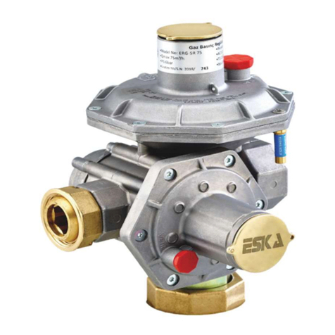
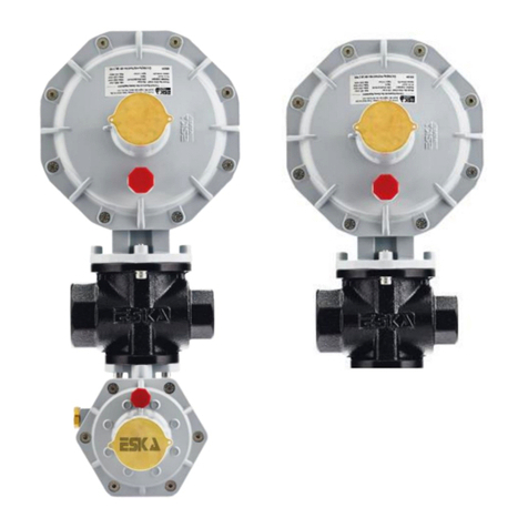
ESKA ERG-SE Series Quick setup guide

ERG-SE SERIES GAS PRESSURE REGULATOR WITH
SAFETY SHUT-OFF DEVICE and
ERG-S SERIES GAS PRESSURE REGULATOR WITHOUT
SAFETY SHUT-OFF DEVICE
ASSEMBLY, USE AND MAINTENANCE INSTRUCTIONS
“Read carefully before all procedures and follow the instructions. Do not carry out any procedure
unspecified in this manual.”
“Retain this manual for future references.”
“The products must only be installed by authorized people.”
“This product must be assembled in accordance with current regulations and guidelines.”
ESKA VALVE A.Ş.
Sakarya 1. Organize Sanayi Bölgesi Mahallesi, 11. Cadde, No: 6-8, Arifiye/Sakarya/Turkey
Web: www.eskavalve.com

The right to change this manual in accordance with the technical developments is reserved. 2014/68/EU Pressure Equipment
Directive has been applied and the manual has been prepared accordingly.
1- GENERAL NOTICE AND CONTROLS TO BE CARRIED OUT
All procedures in this manual must only be carried out by expert personnel who have been licensed by the competent
authorities. Unauthorized people absolutely must not respond to the device. Our company is not responsible for the
malfunctions, damages, accidents, etc. that result from any operation that is not carried out in compliance with the
rules and information in this manual.
End users and unauthorized people must read this manual and follow all safety rules that might be relevant to them.
They must not respond to or tamper with the product under any circumstances, change any settings or make a physical
input. In case of a malfunction, gas leak, etc., they must shut off the inlet valve on the front face of the regulator and
they must notify the relevant gas distribution company and the experts who have been approved by the competent
bodies.
If there's any electrical stress or gas pressure around the product, do not operate it under any circumstances. Respond
appropriately by taking official regulations into consideration. It's prohibited to smoke or light a fire within 2 meters
next to the product. The product must be kept away from chemicals, rain or water. The necessary precautions must
be taken considering that the product may get exposed to natural events such as earthquake, flood, landslide, fire, etc.
Read this manual and the label on the product carefully before any procedure. Retain this manual and the label for
future references. Use the product by following this manual and the instructions provided on the label. If the manual
and/or the label is lost, request a new one from the manufacturer before starting any procedure. If any procedure that
does not comply with this manual or the label is carried out, the product may malfunction or break down, or this may
lead to injuries or loss of life and property. In case there's any doubt before, during or after the procedures, contact
the manufacturer. Keep this manual, the label and the box of the product near the product at all times. After all
procedures, preserve this manual, the label and the box in a safe area. Do not start any procedure before reading this
manual and the product label. If this manual is out of reach, if there's something you don't know, don't understand or
aren't sure about, or if you cannot carry out the procedures even though you comply with this manual; contact the
manufacturer or our representative. Do not exceed the technical limits specified on this manual or the product.
The product has been designed for the conditions and the loads that comply with the intended purpose as well as
sensible and foreseeable working conditions. The product must only be used under design conditions in accordance
with the intended purpose. The working limits specified on the technical properties section must not be exceeded and
any pressure higher than the maximum pressure must not be supplied to the product. No fluids other than the
specified appropriate fluids must be used. Choose the product best suited for you by specifying all conditions. Compare
the integrity of the product to the information on this manual and the label. If everything matches up, move forward
to the assembly stage. Contact the manufacturer before using the product if the information on the manual and the
label do not match. Do not use the product if it does not comply with the field conditions. While sending the
malfunctioning, exchanged and faulty products back to the manufacturer, make sure that the box, related apparatus,
accessories, connection parts, etc. and the label are included. If not, the manufacturer reserves the right not to admit
the products.
For all procedures on this manual and during operations, use the appropriate tools and methods. All products are
placed in special cardboards, boxes and packs in order to avoid any possible damages during shipping and
transportation. During shipping and transportation, all procedures and operations; make sure that the products are
not dropped, thrown, shaken, exposed to overload and excessive force or blow, crushed or stacked with heavy
material, and that the external parts or projections of the product are not damaged, wet or tipped over. The product,
additional parts and spare parts must be stored in their own packages until the assembly. After opening the packs, it
must be made sure that the product and the additional parts are not damaged. In case there are any damages, the
relevant parties must be notified and the product must be kept in its original package for reviewing.

Before, during and after any procedure and during all operations of the product; make sure that the necessary legal
permissions are granted, all relevant parties are informed and notified, all safety measures are taken including personal
protection (goggles, helmet, etc.), the procedures are carried out in accordance with current legislations, regulations,
and technical standards and rules accepted by gas boards, the safety of the working conditions are reviewed, all
necessary precautions are taken against fire risks, the gas is not inhaled, the precautions are taken against dangerous
combinations or any possible emanation of liquids inside the line, foreign objects are not inserted in the release
opening if there is one, no one approaches the device with electrical materials, the operation area complies with the
general protection plan and required safety warnings, and flammable or explosive materials such as fire, spark or
cigarettes are not brought into the area next to the product since it contains flammable gas.
Only the parts that come with the product within the box must be used; unoriginal parts that do not belong to our
company must be avoided. If necessary, contact us in order to procure spare parts. Tampering with the product or
using unoriginal and/or different parts invalidate the warranty. These may also endanger the device's function. At the
end of their life cycle, the products must be replaced with new ones. Follow the legislations and regulations while
sorting, recycling, destroying or disposing of the products, spare parts, non-reusable parts, packaging (pack, box,
stretch), etc. at the end of their life cycle.
At any stage on this manual or during any operation; do not try to remove the product's lever and the shut-off lever
(only on ERG-SE series), do not let them be exposed to any mechanical damage, do not move around or overextend
them.
The product must be set up and activated only after cutting off the product's gas supply and letting an authorized
person determine whether or not there's a gas leak.
If appropriate, it's recommended to use our product regarding the safety of gas lines. The product may only be used
when it's in perfect condition. Faults and malfunctions must be resolved immediately.
The end user and/or the authorized personnel is responsible for applying the right systems in order to protect the
product. Take precautions and develop systems in order to protect the device from outside factors and faulty
procedures such as tampering with the product, opening the lids of the device, introducing substances such as wires,
water, dirt, etc. into the openings of the device, emergencies such as earthquake, fire, flood, etc., corrosion and
chemical effects, environmental impact, adverse weather conditions (rain, snow, frost, moisture (e.g. as a result of
condensation)), mold, UV rays, pests, poisonous or irritant solvents/liquids (e.g. cutting or cooling fluids), direct
sunlight and corrosive atmospheric effects, access by unauthorized people, not being able to detect the gas leak, etc.
Necessary protective measures must be taken considering that static load might occur on the integrated parts of the product or
any other part that is operated along with the product. It's recommended that this value is measured at certain intervals. The
personnel who will check the static load must work with antistatic protective equipment.
2- DEFINITIONS AND ABBREVIATIONS
Device or the Product : ESKA Gas Pressure Regulator
Authorized Body : The gas distribution company that is responsible for distributing gas in the province or the
region
Authorized Installer : In compliance with the laws, regulations and standards; a person authorized by official bodies
who is responsible for installing, assembling, operating, periodically maintaining and inspecting the device; who is
experienced, trained and qualified in this area, has know-how and advanced technical information, knows the laws,
regulations, standards, etc. regarding safety and operations, is experienced regarding all necessary precautions

PS: Maximum Allowed Inlet Pressure
TS: Working Temperature Range
Pds: Outlet Adjustment Pressure
bpu: Inlet Pressure Range
Pdso: High Pressure Safety Shut-off Adjustment Pressure (For the ERG-SE series)
AC: Accuracy Class (± change in outlet adjustment pressure)
DN: Connection Nominal Diameter
Qmax: Maximum Flow Rate
Qmin: Minimum Flow Rate
Pumax: Maximum Inlet Pressure
Pdo: Release Starting Pressure
Wd: Outlet Pressure General Adjustment Range
Wdo: High Pressure Safety Shut-off General Adjustment Range
3- TERMS OF USE, TECHNICAL INFORMATION AND OPERATION PRINCIPLES
Functionally, the regulator reduces the value of the controlled variable (outlet pressure) to the desired/adjusted value
and keeps it within the tolerance range without being affected by the detrimental variables such as flow rate and inlet
pressure. The gas pressure regulator helps the devices that come after itself on the gas line function safely. If requested
on the order, the gas pressure regulator may have a release system that releases to open air. The auxiliary equipment
of the regulator may temporarily release gas to the atmosphere. In this case, necessary precautions regarding the gas
that will be released must be taken before the assembly. The transmission lines are internal in the regulators.
The gas pressure regulator also has a capacity restriction system, which is activated when the outlet flow rate is at
101% to 150%.
The gas pressure regulator is not pilot-operated. It does not have controlling properties. It does not need a bypass unit
in order to function. It is not used as a substitute controlling device. It has a two-stage trigger spring.
On the ERG-SE series gas pressure regulators, there's a high pressure safety shut-off device on the same body (meaning
it's integrated on the regulator), which gets activated when the outlet pressure increases to unwanted levels,
automatically shuts off the gas on the line and remains shut off until being manually set up. This device is functionally
independent from the regulator.
Note: Since there isn't a safety shut-off device that shuts off the pipeline in case of excessively high outlet pressure on
the ERG-S series products, additional precautions must be taken by relevant parties regarding the unwanted excessive
pressure increase on the outlet side of the line.
The technical properties of the product are as follows. These values may vary from product to product depending on
factors such as outlet flow rate, outlet pressure, inlet pressure range, etc. The definitive technical information of the
product is specified on the label. Under any conditions, the product must not be used outside of the restrictions below.
Type-Model-Series: ERG-S and ERG-SE Series
Product Name:
ERG-SE: Gas Pressure Regulator with Safety Shut-off Device
ERG-S: Gas Pressure Regulator without Safety Shut-off Device
Brand: ESKA/ESKA VALVE
Working Temperature Range “TS”: -10 °C; 60 °C or -20 °C; 60 °C (If requested, the LT version: -40 °C; 60 °C)
Area of Use: Service stations and service boxes on the gas lines
Suitable Fluids: Hot Air, Natural Gas, LPG and non-corrosive gases
Maximum Allowed Inlet Pressure: PS6, PSD0.6
Test Pressure: PT=PSx1,5 bar
Connection: Inlet DN15 Threaded, Outlet DN20 Threaded or DN25 Threaded (if requested, modular connection with
nuts)

Line Connection Directions: Q Type, Inline Type, Angle Type, U Type
Outlet Pressure Accuracy Class - Outlet Pressure Tolerance: ±5% AC5, ±10% AC10, ±20% AC20
Outlet Pressure Adjustment Range ( Wd ) : 18-500 mbar
High Pressure Safety Shut-off Adjustment Range (Wdo): 30-800 mbar (Only for the ERG-SE series products)
Inlet Pressure Range (bpu): between 0.1 and 6 bars (0.1-6 Bar / 0.5-6 Bar / 0.7-6 Bar / 1-6 Bar, etc.)
Minimum and Maximum Flow Rate (Qmin-Qmax): 0.25 m3/h - 60 m3/h (Natural gas) (Under standard conditions)
The natural gas flow rate may be converted to the approximate LPG flow rate by multiplying by 1.3, or to the
approximate air flow rate by multiplying by 0.78.
Material Reference Standards: Aluminum Cast Alloy Materials EN 1706, Elastomer Materials EN 549, Brass Materials
EN 12164-EN12165
Filter: Changeable metallic filters are available on the inlet connection part of the product. Plastic or metal filters are
available on the release part. Upon request, filters from changeable metallic materials may be installed on the safety
shut-off device. (Only on ERG-SE series products)
Figure 1 (A: Capacity Restriction Detail, B: On-Demand Release System Detail, C: Safety Shut-off System Detail (Only
for ERG-SE series products))
If requested:
- Appropriate connection and/or nipples in order to measure the pressure or pressure
differential (Figure 1)
- Appropriate connection and/or nipples in order to release the dangerous gas
accumulation (Figure 1)
4- ASSEMBLY
These procedures must be carried out by expert, licensed, authorized technicians or authorized companies, services
or installers that have been certified by the gas board. These procedures absolutely must not be carried out by the end
user. In case the product is not installed appropriately, any malfunction or breakdown may lead to injuries or loss of
life and property. Our company cannot be held responsible for any application that does not comply with the manual.

Before the assembly, determine and make sure with which properties you are going to use the product. Check the
technical and general information specified on this manual and the label on the product. Compare them and make
sure you make the right choice. Pay special attention to the information on the label since it represents the product.
If there are any discrepancies between these information, contact the manufacturer before carrying out any
procedure. Check the accessories and the documents that might be on the product or the box (As shown in Figure 8;
the inlet filter that can be found on the inlet connection side, the outlet gasket (For ERG-SE series No:12, for ERG-S
series No:9), shut-off protection cap number 9 (Only for the ERG-SE series), lever plastic number 7, protection caps on
the connections if they exist, pressure adjustment seals if they exist, release protection cap number 3 if it exists,
manual, alert information if it exists, etc.). Compare the product and the line on which the product will be installed
and make sure they are suitable for each other (working pressure range, outlet pressure, fluid, flow rate,
environmental conditions, cleanliness of the line and the fluid, choosing the connection types and diameters,
compliance of the line and the product dimensions, etc.). If there's something missing or faulty, contact the
manufacturer before carrying out any procedure. You must check and make sure that the product doesn't have any
damages (visual or functional), the product to be installed is suitable for the system, the pressure doesn't exceed the
maximum pressure level specified on the label, the dimensions of the product comply with the line, and the assembly
area is at a safe distance from the sparks or electrical currents that might originate from flammable materials or
devices.
Note: While choosing the flow rate of the regulators, you must determine the maximum capacity of the line where the
product will be installed. Choose a regulator that has a maximum capacity smaller than this value.
The regulator must not be exposed to fire or lightning. For outdoor installments; the regulator must be away from the
traffic or external factors. It must be placed in a way that will prevent water, ice or other foreign substances from
entering the spring box through the ventilation opening. Avoid placing the regulator under a fringe or the downpipes.
Check for a risk of explosive mixtures inside the pipeline. Make sure that the product is above the potential snow level.
The product must be mounted in an aseismic area or in an area where the necessary precautions have been taken for
seismic activity.
Check and make sure that the inlet and outlet pipelines are aligned. Verify that the assembly is being done in
accordance with current technical laws and legislations. While assembling with adjoining components, special
attention must be paid not to apply pressure force on the body, and the assembly components (bolts, o-rings, screws)
must comply with the geometry of the device and the working conditions. You must not make any changes on the
product (drilling, stoning, soldering, etc.). In order to avoid exceeding the usage limits (PS, TS), make sure that the inlet
side is protected with an appropriate device.
Make sure that the connecting components that will be used during the assembly comply with the regulations.
Assemble the product in accordance with the current legislations and local regulations. Obtain the necessary permits
if necessary. Prevent the mixture of explosive gases and air, and control by taking measurements. Avoid any contact
voltage and flammable spark on the product.
There must be an inlet and outlet shut-off valve before and after the regulator on the line where the mounting will be
carried out. Before and during the assembly, make sure that there isn't any compressed gas between the product and
the line or on the line itself. Make sure that the gas supply is shut off and there aren't any possibilities for it to be
turned back on. Before the assembly, it must be checked that the line pressure is within the inlet pressure range
specified on the product label and that the regulator capacity will not be exceeded during operations. Before the
assembly, an adequate buffer volume must be left on the line outlet after the regulator. The recommended buffer
volume is 1/500 of the nominal flow on the products with outlet pressure up to 300 mbar, and 1/1000 of the nominal
flow on the products with outlet pressure over 300 mbar. Necessary precautions must be taken in order to avoid any
noise or vibration originating from the line. There must not be axial misalignment on the line that will be mounted. For
humid gases, necessary precautions must be taken in order to avoid water intake and potential subsequent freezing.
Before the assembly, take the necessary precautions through methods such as clamping on the line part, etc. in order
to reduce the bending and torsional load resulting from the pipes and the jolting on the inlet and outlet sides of the
line. Make sure that the load of the pipeline does not affect the product. Make sure that there aren't any short-range
shrinkage or enlargement of the diameter on the inlet or outlet sides of the product. Ensure that the necessary

dimensions and space are provided by taking the product's external dimensions as reference and taking the future
procedures such as testing, maintenance, removal, etc. into consideration. Verify that the inlet pressure of the product
is higher than the outlet pressure and that it will be higher under all circumstances. Before assembling the product on
the line, clean the internal parts of the pipe with compressed air and eliminate the foreign substances such as dust,
dirt, sawdust, welding particles, etc. Take the necessary measures to prevent these lines from getting contaminated
again. Carry out the general pressure and tightness controls of the line and the system. Make sure that an external
filter is installed in order to filter out the gas before the gas pressure regulator. Assemble the products by taking the
necessary precautions (e.g. inside a protective box, etc.) so that they won't be exposed to external damage or impact
resulting from the environmental factors or external corrosion (sunlight, rain, snow, moisture, water, external
chemicals, etc.)
In order to start the assembly: Obtain the necessary permits from the gas distribution companies. Take all necessary
measures considering all risk variations and combinations. Make sure that all valves that supply gas to the product are
turned off and there's no gas flow. If they need to be used, make sure that the connection components comply with
the regulations. Do not use materials such as putty, special liquids, etc. in order to ensure tightness in the connections.
The gaskets that will be used during the assembly must be the appropriate and licensed gaskets, and they must be new
with the appropriate rigidity. Make sure that the gaskets do not have a flaw that will affect their tightness properties.
Remove the product from the box and manually remove the inlet-outlet connection protection caps if they exist. Make
sure that the inlet filter is correctly mounted on the inlet connection part. If it's not, mount it manually. Manually place
the outlet gasket that comes inside the box (No:12 for ERG-SE, No:9 for ERG-S) on the outlet connection nozzle (always
use new and licensed gaskets). Set the flow direction of the product in a way that the arrow on the product's body
indicates the outlet side and the gas flow direction. With a tolerance range of ±5oC, set the position of the product for
the dry gases horizontally or vertically like it has been specified on Figure 1, provided that the upper hatch part, which
includes the outlet pressure adjustment part, does not face the floor. If the fluid is LPG, set the position by making sure
that the regulator outlet side faces the floor. Place the product on the line without applying excessive load, force or
impact and in a way that will not block the product's outlet sense line or will not expose it to mechanical stress. Tighten
the product's inlet and outlet connections number 6 (No: 11 for ERG-SE, No:8 for ERG-S) by using the appropriate
wrench without using excessive load, force or impact; making sure that there aren't any external leaks. After the
tightening procedure; make sure that the connections settle in the bearings perfectly, that there aren't any mechanical
problems on the connections such as fractures, etc., and that there aren't any mechanical stress on the product
originating from the line, pipe or connections.
If the product has flanged connections; observe that the inlet and outlet flanges are the same as the line connecting
flanges in order to prevent unnecessary mechanical stress on the product body. Make sure that they are aligned
perfectly and are parallel to each other. Tighten the nuts and bolts gradually in a diagonal pattern in gradually
increasing torques. Tighten each nut clockwise at least once more until the maximum torque is obtained. Also,
calculate the necessary gap to place the tightness gasket and center the gaskets appropriately in the connection. If
there's a gap between the line and the product, do not try to reduce the gap by tightening the gaskets more than
necessary.
Provide protection for the product (e.g. by storing it in a box, etc.) so that unauthorized personnel do not tamper with
it, bump into it or accidentally touch it. After the assembly is completed, check and make sure that you have not
assembled the product the wrong way around, that you have complied with current laws and local regulations, and
that you have carried out the procedures in accordance with the information on this manual.
The relevant restrictions must be taken into consideration regarding the reaction and momentum resulting from the
pipe and the connections. In case the connection components that have been installed on the inlet and outlet sides of
the product are bigger than the connection diameters on the product's body (fittings, nozzles, etc. before installment),
you must not use any force or momentum that exceeds the values required by the main connection diameter on the
body and you must not go over the restrictions. In this context, the bending and torsion load limits of the product may
change according to the direction of the line connection. Regardless of the product's inlet and outlet pipe connection
diameters or nozzle diameters; the maximum loads that can be applied on the product are 10.5kg bending and 5kg
torsion on the inlet sides, 34kg bending and 12.5kg torsion on the outlet side that has a bigger diameter, and 22.5kg
bending and 8.5kg torsion on the outlet side that has a smaller diameter. It's recommended that the impact of these
loads do not go over 10 seconds. Otherwise, the product may malfunction.

If the products are going to be used in floor type applications, this must be specified during the order stage. In this
case, the products that have been appropriately coated on the outer surface must be used. Necessary precautions
must be taken in order to prevent dirt, dust, liquid, etc. from entering the release part of the product if it exists. Also,
it must be made sure that the products are not used while completely or partially immersed in water, earth or other
liquids. If necessary, the exhaust line must be connected to the ventilation console of the regulator. This connection
must be at least DN10 threaded. The threaded adaptor that might be necessary for this connection must be requested
and used. The gas pressure regulators with a release system must not be mounted indoors or on floor type applications
without taking the necessary precautions for the gas to be released into a safe area (for instance, the released gas
must be released and mixed into the atmosphere through at least a DN10 pipe, etc.).
✓
✓
X
Figure 1
5- SETUP, START-UP AND OPERATING
Before the setup, carefully read the instructions on this manual and the information on the product label. Keep them
close and strictly follow them. If you think there's missing or faulty information, do not carry out any procedures and
contact the manufacturer.
Before the setup, check and make sure that the people at the outlet side are not using the device. Do not change the
factory settings. The factory settings have been adjusted according to the values requested on the order contract and
they have been specified on the label. The adjustment equipment are sealed if requested on the order contract. Give
the necessary warnings so that the end users do not use it. Before starting the setup, you must first shut down the
main gas supply. Before setting up the device, make sure that the product has been assembled correctly on the line.
During the setup, prevent particles such as dirt, rust, dust, etc. from entering the device and take lasting precautions.
Not getting rid of the residue leads to damages or faulty performance.
During the start-up, unauthorized personnel must absolutely be kept away from the device and the limited access area
must be appropriately marked (signs, barriers, etc.). During the start-up; in case flammable or hazardous fumes are
released into the atmosphere, the risks that have been determined in case of a discharge must be assessed. During
the setup, take into consideration the risk of generating an explosive mixture (gas/air) in the pipes. Take the necessary
measures. Make sure the ventilation and/or the exhaust lines on the product are not obstructed. Take the necessary
precautions to make sure that these lines are not obstructed in the future. Do not install caps on these lines such as
blind caps that may block the gas outflow.
For the ERG-SE series products;
In order to begin the setup: Partially turn on the outlet valve on the line. Slowly and gradually turn on the inlet valve
on the line, which is the gas supply. Manually turn the transparent shut-off protection cap number 9 counterclockwise
to remove it (procedure no:1 on Figure 2). Manually and slowly pull the shut-off lever number 8 towards yourself

without applying any excessive load, force or impact. Wait for a couple of seconds to make sure that the lever remains
pulled, and then set up the shut-off part. If this procedure is not completed successfully, repeat it. Then, reattach the
shut-off protection cap number 9. Manually turn the lever number 7 counterclockwise slowly and gradually without
overextending or using excessive load, force or impact (procedure number 2 on Figure 2). Set up the device by verifying
that there's a gas flow on the outlet side, the lever number 7 has gone back to its initial position, and the shut-off lever
number 8 has remained pulled and locked. If this process does not occur, repeat the procedure. (During these
procedures, if you have difficulties turning the lever number 7, have difficulties pulling the shut-off lever number 8, or
if the shut-off lever number 8 turns off because the outlet pressure reaches the safety adjustment pressure; you may
carry out procedures such as removing the release protection cap number 3 if it exists (procedure number 3 on Figure
3), gradually turning on the inlet valve instead of completely turning it on, letting a small amount of gas to be released
from the test nipple on the outlet line, pulling and holding the shut-off lever number 8 for 3 to 5 seconds while locking
the lever number 7 and letting go of the shut-off lever number 8 when you detect a gas flow on the outlet side and
verifying that the lever remains pulled, etc. After these procedures, reattach the parts that you have removed such as
the release protection cap number 3, test nipple, etc.)
For the ERG-S series products;
In order to begin the setup: Partially turn on the outlet valve on the line. Slowly and gradually turn on the inlet valve
on the line, which is the gas supply. Manually turn the lever number 7 counterclockwise slowly and gradually without
overextending or using excessive load, force or impact (procedure number 2 on Figure 2). Set up the device by verifying
that there's a gas flow to the outlet side. If this process does not occur, repeat the procedure. (If you have difficulties
turning the lever number 7 during these procedures; you may carry out procedures such as removing the release
protection cap number 3 if it exists (procedure number 3 on Figure 3), gradually turning on the inlet valve instead of
completely turning it on, letting a small amount of gas to be released from the test nipple on the outlet line, etc. After
these procedures, reattach the parts that you have removed such as the release protection cap number 3, test nipple,
etc.)
After setting up the device; manually reattach the shut-off protection cap number 9 for the ERG-SE series products
and the release protection cap number 3 for all products if it exists. Make sure that there's a gas passage to the outlet
side, that the lever number 7 has remained in the same position prior to the setup, that the shut-off lever number 9 is
in the drawn position for the ERG-SE series products, and that the released gas can be mixed into the atmosphere if a
release system exists on the product. Inform the gas users regarding gas usage.
Besides, after setting up the device, make sure that the inlet and outlet valves are on and that there's pressure on the
outlet side. Check all external parts of the product including the connections by using methods such as appropriate
foam, liquid, detector, etc. and verify that there isn't any external leak on the product or excessive noise or vibration
on the line or the product. Connect the appropriate manometer, which has been connected to the pressure source, to
the test valve that is located on an appropriate spot at the outlet line after the regulator (during this procedure, make
sure that the connections are tight and leakproof). When there's a consumption of 0,5xQmax on the outlet side of the
regulator, measure the outlet pressure and check whether or not it's within the tolerance range. Shut off the outlet
valve on the outlet side of the regulator and wait for a while. Check whether the outlet pressure is stable and there
aren't any internal leaks. In order to make sure that the external leak or the released gas originating from the product
do not create a dangerous atmosphere while carrying out this procedure, take all necessary measures and do not
operate it indoors. The procedures that may lead to pressure inflow to the inlet connection nozzle and the body higher
than the determined PS value must not be carried out under any circumstances and this situation must not be allowed.
Analyze the pressure values with the calibrated manometer that has been assembled at least 5xDN on the outlet
pipeline. In order to avoid any kind of gas leak or fizzling out of the gas burning device, etc. by the user during all these
procedures, the users must be informed appropriately and the necessary measures must be taken.
During the setup procedure or during mid-season, as a result of temperature difference, etc., there may be a gas
outflow into the atmosphere from the release part of the product. This is normal. It's important that the gas outflow
in question is not continuous. If the gas outflow is continuous, there might be a malfunction in the product. In this
case, do not keep using the product. Immediately contact the authorized people and competent bodies, and take the
necessary safety measures on the line.
At indoor areas, the leaked gas may accumulate and create a risk of explosion. In such cases, the connection must be
carried out through a pipe from the product's ventilation hole to the outdoors (atmosphere).

If the gas pressure regulator is shut down during operation for some reason; the inlet valve must be shut down, the
problem must be detected, and it must be re-setup according to the rules explained above.
On the ERG-SE series products, the outlet pressure may increase while operating due to the abrupt stopping of the
boiler or an internal leak originating from unclean air or the foreign substances on the line. When this happens, the
product's high pressure safety shut-off device may be turned off and the gas on the outlet side of the regulator may
be cut off. The position of the safety shut-off can be observed via the lever number 8 which is inside the transparent
cap number 9. In this case, the setup procedure must be carried out once again.
During operation, if there's an increase in capacity by 101% to 160% of the maximum capacity specified on the
regulator, the capacity restriction system is activated and the gas flow is cut off. In this case, the setup procedure must
be repeated. (In this case, the shut-off lever number 8 on the ERG-SE products remains in the locked position and is
not turned off, but the gas has been cut off by the regulator)
6- SETTINGS
If necessary for a variety of reasons, the product's outlet pressure and safety shut-off pressure settings (for ERG-SE
series products) must be carried out as follows. Under normal conditions, there's no need to change these settings.
These settings must be changed if the authorized people think it's necessary.
The settings must not be changed more than ± 10% and outside the restrictions on the label.
The seals on the adjustment parts of the product must be removed if they exist. While carrying out the pressure
settings, the adjustment mechanisms and the springs must not be pressed or forced. Connect the pressure gauge or
the manometer on an appropriate test valve between the regulator and the outlet pipe in order to see the setting
values. During all adjustments, turning it clockwise leads to pressure increase and turning it counterclockwise leads to
pressure decrease. When the outlet pressure is increased, the safety pressure must be increased as well.
In order to change the outlet adjustment pressure: manually turn the cap number 1 on Figure 8 counterclockwise to
remove it. Turn the adjustment ring number 2 towards the appropriate direction with a 27mm hexagonal wrench.
Mark the adjustment pressure. Manually turn the cap number 1 clockwise to reattach it.
Note: While setting the appropriate pressure for the product, it's recommended that you set the capacity value on the
outlet side to 0,5xQmax. This value must not be below 0,1xQmax under any circumstances.
In order to change the high pressure safety pressure on the ERG-SE series products: manually turn the cap number 9
on Figure 8 counterclockwise to remove it. Turn the adjustment ring number 10 on Figure 8 towards the appropriate
direction with a 13mm hexagonal wrench. Mark the adjustment pressure. Manually turn the cap number 9 clockwise
to reattach it.
In order to change the release system release adjustment pressure if it exists: manually turn the cap number 1 on
Figure 8 counterclockwise to remove it. Turn the adjustment ring in the internal part on Figure 4 towards the
appropriate direction with a 16mm hexagonal wrench. Mark the adjustment pressure. Manually turn the cap number
1 clockwise to reattach it.
After changing the settings; check and verify with appropriate methods that the technical properties and the
restrictions on this manual and on the product are complied, the product does not continuously release gas into the
atmosphere, the outlet pressure is at the desired level, and all procedures are carried out safely and correctly. After
making the pressure adjustments in question, it's recommended that the adjustment equipment is sealed on the
products that are being used in the field so that the adjustments cannot be changed. For this procedure, the seal inside
the box may be used if it exists.
Note: When the outlet adjustment pressure of the product is changed, taking into consideration the changes in the
working conditions, it must be verified that the pressure values are not close to the release adjustment pressures (if it
exists) and safety adjustment pressures, and that they are not within this range. Otherwise, the product continuously
releases gas into the atmosphere or the product's safety shut-off mechanism may get activated and unexpectedly cut
off the gas, which may lead to dangerous situations. It must be made sure that these situations do not occur after the
settings are changed.

Figure 4
ERG-SE Series Products
ERG-S Series Products
Figure 2

Figure 3
7- PERIODICAL MAINTENANCE AND INSPECTION
Periodical inspection is recommended for making sure that the regulator functions safely and properly. The frequency
of periodical inspections must not exceed the limits specified by the gas board or the regulations. The maintenance
period must be adjusted according to the working conditions. End users must not carry out any maintenance procedure
for the product.
During all procedures, the instructions on this manual must be complied. All periodical maintenance procedures must
be carried out after removing the product off the line. Do not carry out abrupt discharge in order to clean the line after
the product under any circumstances. Do not start any maintenance procedure before releasing the internal pressure
that might have accumulated inside the product. For the necessary periodical maintenance, remove the product off
the line in accordance with the disassembly rules specified on this manual.
For the necessary periodical maintenance that does not have to be carried out on the line, remove the product off the
line according to the removal rules specified on this manual. Manually remove the filter that has been mounted on the
nozzle on the inlet connection side and the outlet gasket that has been mounted on the outlet connection nozzle.
Clean them appropriately. If necessary, replace them with new ones. Then, remount them. Remove the screws on the
regulator caps without any stress using appropriate tools and remove the caps manually. Do not remove the parts of
the caps that have been removed. Keep the caps as a whole with their parts inside. Clean these parts slowly with a
clean washcloth. On the ERG-SE series products, you must also remove and clean the filter inside the shut-off valve if
it exists. Make sure that the connection components of the product (screws and/or gaskets and nuts) are mounted
and removed using the specified torques. Mount the caps using the same screws, without applying stress on the screws
or using excessive force by tightening them so that they align with the holes. Make sure that they are not loose or that
they have not been exposed to any mechanical damage. When the maintenance is completed, assemble the product
on the line and set it up according to this manual.
Note: If there's any kind of paint, lacquer, seal, etc. on the connection parts of the regulator such as screws, etc., do
not carry out any maintenance procedures and contact the manufacturer. Do not carry out the cleaning procedure
with cleaning supplies that contain alcohol or solvents. After the periodical maintenance procedure, it's under the
responsibility of the institution that carries out or requests the periodical maintenance to make sure that the product
is operated safely and correctly at values that have been specified by the manufacturer. In this context; in cases where
you have any doubts, you must not install the products on the line and you must contact the manufacturer.
For the periodical maintenance that can be carried out on the line without removing the product, make sure that the
inlet and outlet valves are turned on and that there's pressure on the outlet side. Check all external parts of the product
including the connections by using methods such as appropriate foam, liquid, detector, etc. and verify that there isn't
any external leak on the product or excessive noise or vibration on the line or the product. Connect the appropriate
manometer, which has been connected to the pressure source, to the test valve that is located on an appropriate spot
at the outlet line after the regulator (during this procedure, make sure that the connections are tight and leakproof).

When there's a consumption of 0,5xQmax on the outlet side of the regulator, measure the outlet pressure and check
whether or not it's within the tolerance range. Shut off the outlet valve on the outlet side of the regulator and wait for
a while. Check whether the outlet pressure is stable and there aren't any internal leaks. In order to make sure that the
external leak or the released gas originating from the product do not create a dangerous atmosphere while carrying
out this procedure, take all necessary measures and do not operate it indoors. The procedures that may lead to
pressure inflow to the inlet connection nozzle and the body higher than the determined PS value must not be carried
out under any circumstances and this situation must not be allowed. Analyze the pressure values with the calibrated
manometer that has been assembled at least 5xDN on the outlet pipeline. In order to avoid any kind of gas leak or
fizzling out of the gas burning device, etc. by the user during all these procedures, the users must be informed
appropriately and the necessary measures must be taken.
After the tests in question, make sure that all accessories and apparatus such as the shut-off protection cap (on the
ERG-SE series products), the lever plastic, the pressure adjustment seals if they exist, the release protection cap if it
exists, the release sieve if it exists, etc. are mounted on the product. Set the device up by following the setup rules
specified on this manual.
If any problems are observed during periodical maintenance or inspection, the necessary procedures may be carried
out in accordance with the rules explained in the malfunction section.
8- CUT-OUT, REMOVAL AND CHANGING
Before, during and after all removals and changes, follow the rules specified on this manual and carry out the necessary
procedures. Before and during the removal and changing procedures; make sure that there's no compressed gas on
the line and between the line and the product, that the gas supply is shut off, and that the possibility of turning back
on is completely prevented.
Turn off the inlet and outlet valves that are located on the line at the back and the front of the regulator. Release the
compressed gas that has accumulated between the line and the product safely and gradually through the part between
the gas pressure regulator and the outlet valve. Remove the inlet and outlet connections off the line with an
appropriate wrench without using excessive load or force. If it's going to be replaced with a new product, assemble
and set up the new product according to this manual.
9- MALFUNCTIONS, REPAIR, PROBLEMS AND SOLUTIONS
Before, during and after all malfunctions, follow the rules in the order specified on this manual and carry out the
necessary procedures. Pay special attention to informing the end users and take the necessary precautions against the
dangers of compressed gas.
End users must not carry out any repairing procedures on the product. All repairing procedures must be carried out by
authorized services and personnel. The people other than users or authorized personnel must not respond to the
product and the line in case of a malfunction.
If you suspect a malfunction, it's recommended that you carry out the procedures on Table 1 according to the type of
the problem. If you do not want to carry out these procedures, or if you cannot eliminate the problem even after you
carry them out; do not try to interfere with the product any more. Remove the product off the line according to the
rules of removal specified below without trying to open it up, send the product to our company, and install a new
product on the line. The maintenance, repairing and changing procedures must not be carried out in a way that will
interfere with the internal parts of the product.
The maintenance and repairing must be carried out on empty systems and products that have been removed off the
line. Only use original spare parts.

Problems and Solutions
Problem Code
Problem
Codes for the procedures in order
P1
Dirty filter
10,11
P2
Auto setup
12,1
P3
Mechanical damage
1
P4
Unable to setup
13,9,1 (Also, No:25 must be carried out for
the ERG-SE series products, and No:14 must
be carried out for the ERG-S series products)
P5
No gas passage
3,15 ,16,17,18,10,11,5,2,4,25,1
(Also, No:26 must be carried out for the ERG-
SE series products, and No:14 must be
carried out for the ERG-S series products)
P6
External leak
16,17,18,1
P7
High outlet pressure outside the
tolerance range
8,7,2,1
P8
Low outlet pressure outside the
tolerance range
16,17,18,5,6,3,2,1
P9
Release system errors
7,8,2,1
P10
Insufficient flow rate
3,10,11,4,2,1
P11
Missing accessories
23 for the ERG-SE series products
21 for the ERG-S series products
P12
Noise and Vibration
24 for the ERG-SE series products
19 for the ERG-S series products
P13
Shut-off errors
Only on ERG-SE series products; 19,27,
measure the outlet pressure to see if it
increases, carry out the procedures 7,8,2 if it
does, 20,21,25,1
Table 1
Descriptions of the codes for the procedures to be carried out in order during problems
1- Change the product with a new one
2- Measure the outlet adjustment pressure and fix it if erroneous
3- Make sure that you did not choose the wrong product regarding the flow rate and the outlet pressure
4- Measure the inlet pressure and make sure that it's not less than the minimum inlet pressure
5- Check to see if there's a thrust higher than the product's capacity
6- Examine if there's an external leak on the outlet line
7- Check whether or not there's an excessive diameter shrinkage on the outlet line
8- Stop the gas thrust on the outlet side, turn off the inlet valve and then turn it back on, reactivate the product and
check the result
9- Remove the product off the line and try again after reassembling
10- Remove the product off the line, manually remove the filter on the inlet connection nozzle and clean it, manually
place the new filter if necessary, remount the product on the line.
11- Take precautions for cleaning the line
12- Check whether or not the product has an automatic setup system
13- Loosen the protection cap number 3 if it exists, turn down the inlet valve a little, momentarily relieve the
compressed pressure on the outlet side, and then reverse all procedures. Also, on ERG-SE series products, check
whether or not the shut-off lever number 8 turns off. If it does, check to see that there isn't excessive narrowing on
the line outlet. Then, when carrying out the setup procedure, pull and hold the shut-off lever number 8,
14- For the ERG-SE series products, check whether or not the shut-off lever number 8 is shut off. If it's shut off, re-
setup the product and check the result. For the ERG-S series product, try setting up the device again.
15- Check to see if there's any congelation on the line or on the water that has the possibility of entering the product
16- Check if there is a loose connection or screw. If there are, tighten them according to the rules (do not carry out this
procedure if there's a seal on the screws)

17- If there's a leak on the outlet connection nozzle, remove the product off the line. Manually remove the outlet
gasket. If there aren't any problems visually, reattach the gasket and remount the product on the line.
18- If there's a leak on the release part, check to see that there isn't excessive diameter narrowing on the outlet line.
If there isn't, stop the gas thrust on the outlet side. Turn off the inlet valve, turn it back on, reactivate the product and
check the results
19- On ERG-SE series products, check if there's an indication of an impact or a tilt on the shut-off lever number 8. On
ERG-S series products, check if the assembly position is correct, if there's a fluctuation of the inlet pressure, if there
are any unwanted narrowings such as in the diameter, etc. in the area close to the outlet side.
20- Check to see that there isn't a narrowing on the outlet sense line
21- On ERG-SE series products, measure the shut-off adjustment pressure and correct it if there's an error. On ERG-S
series products, detect the missing parts such as the lever plastic number 8, the pressure adjustment seals if they exist,
release protection cap number 3 if it exists, release sieve number 5 if it exists, etc. and manually mount them
23- Detect the missing parts such as the shut-off lever number 9, lever plastic number 8, the pressure adjustment seals
if they exist, release protection cap number 3 if it exists, release sieve number 5 if it exists, etc. and manually mount
them
24- Check if the assembly position is correct, if there's a fluctuation of the inlet pressure, if there are any unwanted
narrowings such as in the diameter, etc. in the area close to the outlet side.
25- Try setting up the product again.
26- If the shut-off lever number 8 is turned off; notify the relevant parties, make sure that there’s no gas usage, and
set up the product again according to the rules.
27- Check to see if there might have been an increase in pressure on the outlet flow due to the abrupt stopping of the
boiler
10- DIMENSIONS, LINE CONNECTION DIRECTIONS AND INFORMATION ABOUT THE
PARTS
The measurements are in millimeters. The connections below are modular and they can be changed by the
manufacturer.
Figure 5

Figure 6
Figure 7

ERG-SE Series Products
ERG-S Series Products
Figure 8
1- Outlet pressure adjustment hatch
2- Outlet pressure adjustment ring
3- Release protection cap
No:5 on the ERG-S series products, No:4 on the ERG-SE series products - Upper hatch screws
No:4 on the ERG-S series products, No:5 on the ERG-SE series products - Release sieve
6- Inlet connection nozzle
7- Lever plastic and lever
No:8 on the ERG-S series products, No:11 on the ERG-SE series products - Outlet connection nozzle
No:9 on the ERG-S series products, No:12 on the ERG-SE series products - Outlet gasket
Besides, specific to the ERG-SE series products;
8- Shut-off lever

9- Shut-off protection cap
10- Shut-off adjustment ring
11- LABEL INFORMATION
On all ERG-SE series products and on ERG-S series DN32, DN40 and DN50 products
For DN15, DN20 and DN25 on ERG-S series products

12- STORAGE-PRESERVATION-LIFTING-HANDLING-SHIPMENT-LOADING-
TRANSPORTATION
The following conditions must be taken into consideration for all products and spare parts:
In order to prevent the damages on the product that may occur during shipment and transportation, our company
delivers the product to the customer by placing it in a single or double cardboard, box or package.
Carry out the loading-handling-lifting-storing procedures correctly. The product may not function properly due to the
reasons such as throwing, excessive shaking, tipping over, falling down, crashing, exposure to overload and excessive
force or impact, crushing, stacking with weight, as well as damaging, moistening or tipping over the external parts
and projections, etc. Our company cannot be held responsible in such cases.
The product must not be exposed to direct sunlight.
Store it indoors, in an air-conditioned, dim, dry and clean environment.
Make sure that the product is protected from rain, water, snow, extreme heat or cold, etc. during shipment,
transportation and storage.
There must not be any direct heat source in the storage area.
Make sure that the operation floor is flat and clean, and isn't wet and slippery.
Do not overload or elevate during shipment.
There must not be any residue, moisture or wetness on the product while repacking.
The product must be stored in areas that have been protected against forces such as falling, tipping over, shock,
impact, vibration, etc. and that are protected from the conditions of corrosion or wearing out (sun, atmosphere, rain,
snow, moisture, water, external chemicals, etc.), in a way that will not be affected by natural events such as
earthquakes, floods, fire, etc. or adverse weather conditions as well as dirt, mud or contamination.
Do not remove the products from the original box or package unless they will be used. Do not replace the box or the
package.
The period of storage is subtracted from the product lifecycle and the time of warranty.
Storage temperature must be between 5° C and 20° C .
The impact of the UV rays and ozone must be eliminated during transportation-shipment-storage (especially for the
elastomeric parts).
Pay special attention to the external parts and projections.
Storage must be carried out without electrical stress.
If there's any surface treatment on the product (sandblasting, coating, dyeing, etc.), it must not be damaged during
shipping.
Product
Number
or
Items
Box
Dimensions
(LxWxH
cm)
Unit
Weight
Package
Size
(LxWxH
cm)
Number
of Boxed
Products
in 1
Package
Package
Weight
Total
Package
Weight
Pallet
Total
Items
Pallet Total
Weight
ERG-SE
1
15x14,5x16
Approximately
1,15kg
33x58x35
16
0,65 kg
19,5 kg
480
Approximately
600 kg
ERG-S
1
15x14,5x16
Approximately
1,10kg
33x58x35
16
0,65 kg
18,2 kg
480
Approximately
580 kg

WARRANTY CERTIFICATE
The Manufacturing Company's;
Title: ESKA VALVE A.Ş.
Address: Sakarya 1. Organize Sanayi Bölgesi Mahallesi, 11. Cadde, No: 6-8, Arifiye/Sakarya/Turkey
Telephone : +90 (264) 502 54 34-35
Fax : +90 (264) 502 54 84
Authorized Signature:
Company Stamp:
The Vendor's;
Title:
Address:
Telephone:
Fax:
E-mail:
Authorized Signature:
Company Stamp:
The Product's;
Type: Gas Pressure Regulator
Brand: ESKA / ESKA VALVE
Model-Series: ERG-SE or ERG-S
Warranty: 2 years
Maximum Time To Repair: 20 business days
Invoice Date and Number:
Date of Delivery to the Consumer:
Place of Delivery to the Consumer:
Banderole and Series Number:
This manual suits for next models
1
Table of contents
Other ESKA Controllers manuals
Popular Controllers manuals by other brands
Compu-aire
Compu-aire SYSTEM 2200 Plus 3L user manual
Nederman
Nederman SER.537 instruction manual
ABB
ABB RELION 650 SERIES Commissioning manual
LAMBERTI ELEKTRONIK
LAMBERTI ELEKTRONIK LATHERM SOL MAXIMAL Commissioning manual

PIKO
PIKO SmartControl Quick manual
Emerson
Emerson Advantage 2.1 Installation, operation and maintenance manual

Securam
Securam BSL-0601A-D66 user manual

Paragon
Paragon TnF 2 installation guide
Danfoss
Danfoss HFX Series Installation and operation manual

Cisco
Cisco Catalyst 9800-80 installation guide
PI
PI P-840.XXV Series user manual

ARI-Armaturen
ARI-Armaturen ARI-PREMIO-Plus 2G Operating and installation instructions
