ESKA ERG-SR Service manual

1
MODEL ERG-SR
GAS PRESSURE REGULATOR WITH DIRECT
EFFECTIVE SAFETY SHUTDOWN SYSTEM
INSTALLATION, USE AND MAINTENANCE MANUAL
“Read carefully before all procedures and follow the instructions. Do not carry out any procedure
unspecified in this manual.”
“Retain this manual for future references.”
“The products must only be installed by authorized people.”
“This product must be assembled in accordance with current regulations and guidelines.”
ESKA VALVE A.Ş
Sakarya 1. Organize Sanayi Bölgesi Mahallesi, 11.Cadde, No:6-8, Arifiye /Sakariya/TURKEY
Telefon: +90 (264)502 54 34-35 Fax: +90 (264)502 54 84 E-mail: [email protected]
Web: www.eskavalve.com
The right to change this manual in accordance with the technical developments is reserved. 2014/68/EU Pressure Equipment Directive
has been applied and the manual has been prepared accordingly.

2
1-GENERAL WARNINGS AND REQUIRED CONTROLS
Please read this instruction carefully before proceeding and do not perform undefined operations, use the product in
accordance with the information contained in this instruction manual and its label, otherwise the product may not operate
properly, or be injured or damaged. All operations described in this manual should only be carried out by qualified
personnel who have been approved by the competent authorities.
End users and unauthorized persons should read this instruction, comply with all safety rules that may concern them, in
any case not to interfere with the product or even to interfere, to change the setting and to try to make physical entry, to
detect malfunction or gas leak. The regulator must close the inlet valve on the front and inform the relevant gas
distribution company and the specialist. The regulator is not allowed to smoke or fire until 2 meters away.
Do not start operations without accessing and reading this instruction. If you cannot reach this instruction, there are topics
that are not understood, unknown or sure before starting any operation, or you cannot carry out the operation if you
follow the instructions written in the instructions during operation and if you are having problems, please contact us or
our representative.
For all operations in this order and during use; Use appropriate tools and methods. We ensure that products or boxes are
not dropped, thrown, shaken, overburdened, force and impacted, not crushed, no weight placed on them, no damage to
external parts and external protrusions, no heavy loads and no overturns in all processes and use.
During any operation, before, during and after all use of the product; provide to take all necessary precautions including
personal protection, take the necessary legislations, regulations, procedures in accordance with the technical standards
and rules of the gas organizations, take all necessary precautions against the risk of fire, take in the inhalation of the gas,
take the necessary legal precautions, inform and warn all the interested parties about the transactions, take precautions
against hazard combinations, take adequate precautions against possible flushing of liquids in line, prevent foreign matter
from entering the discharge hole, avoid explosion and fire-related substances such as fire, sparks and cigarette smoke due
to combustible gas and to not used.
Parts other than those supplied with the product and box that are not original and do not belong to my company should
not be used. Contact us to supply spare parts. All necessary actions and precautions should be taken in consideration that
they may be exposed to natural phenomena as Product earthquake, flood etc.. At the end of its life, products must be
replaced with new ones.
Do not attempt to remove the product shut-off bracket and product bracket from the ground, allow mechanical damage
to be exposed, move to the right or to the left unnecessarily, and do not overstress during any stage and use in this manual.
Keep this instruction in a safe area after all operations. Failure, damage, accident etc. due to failure to follow the rules and
information in this instruction The manufacturer is not responsible for these situations. Do not exceed the technical limits
in this instruction.
2-OPERATION-TERMS OF USE AND TECHNICAL SPECIFICATIONS:
The gas pressure regulator helps the subsequent devices in the gas line to operate safely. The gas pressure regulator
maintains the outlet pressure within the tolerance range by lowering the inlet pressure to the desired / adjusted outlet
pressure and automatically detects the outlet pressure in the event that the outlet pressure does not reach undesirable
levels on the safety regulator, or automatically detects this situation, Has a high and low pressure gas safety shut-off device
3
associated with the ongoing gas pressure regulator. The gas pressure regulator may have a type of evacuation system
which is opened to the air if ordered. The auxiliary equipment of the regulator may temporarily evacuate the gas. In this
case, the necessary precautions regarding the gas to be evacuated must be taken before mounting. 84/5000
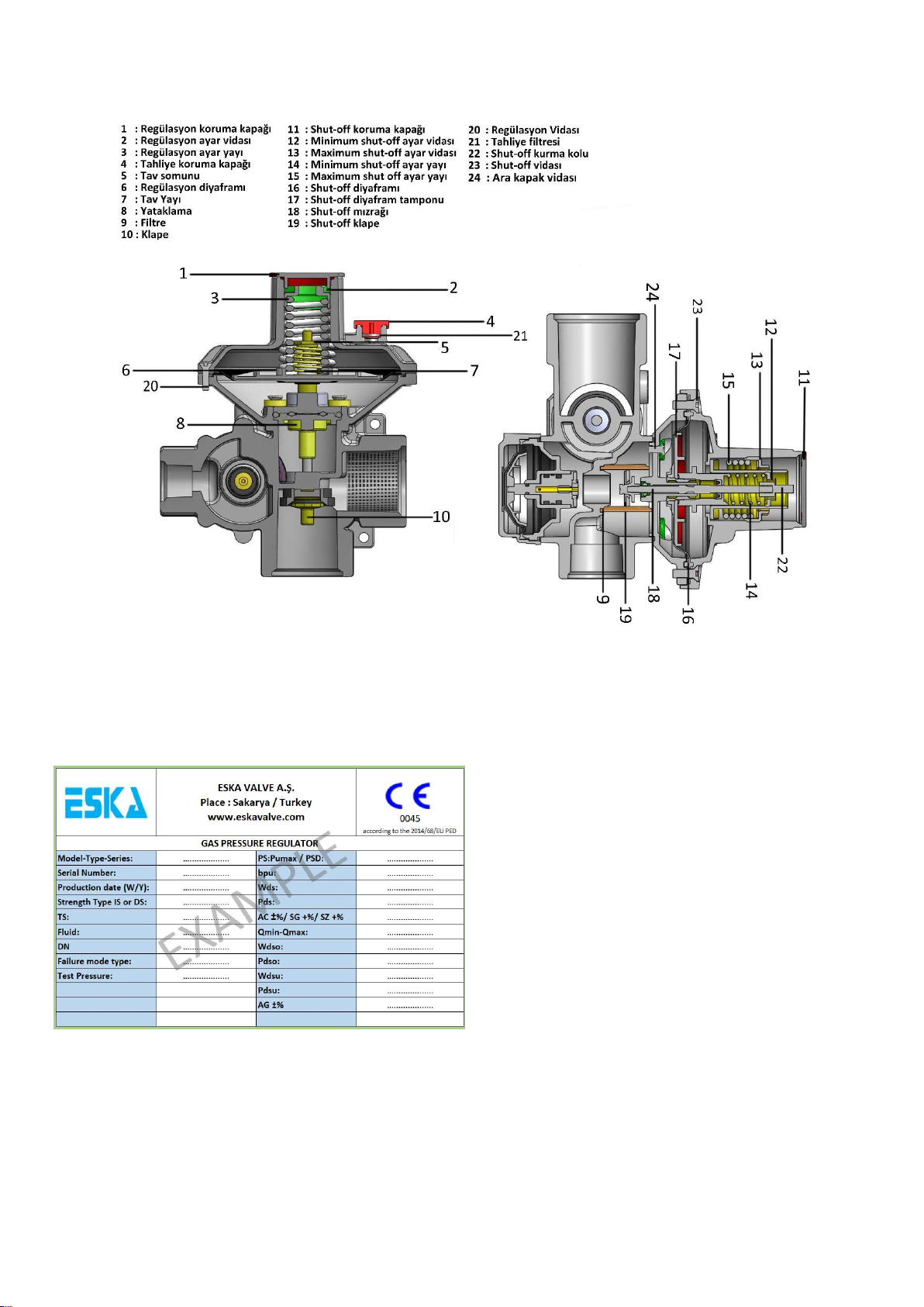
The detail of the safety closing and evacuation system on the product is shown in figure-3.
The gas pressure regulator is not pilot controlled, it does not have a controller feature, it does not need a bypass unit to
operate it, it is not used as a backup control device, it is double stage, direct working principle, internal sensing and spring
drive
The technical specification ranges of the products are as follows. These values are output to product, outlet pressure, inlet
pressure range etc. Depending on the factors. The final technical information of the product is stated on the product label.
In no case should the following restrictions be used.
Area of Use: Service stations and service boxes on gas lines, commercial and industrial gas pipeline applications
Suitable Fluids: Natural gas, LPG and non-corrosive gases
Permissible Maximum Input Pressure: PS6, PSD0,6
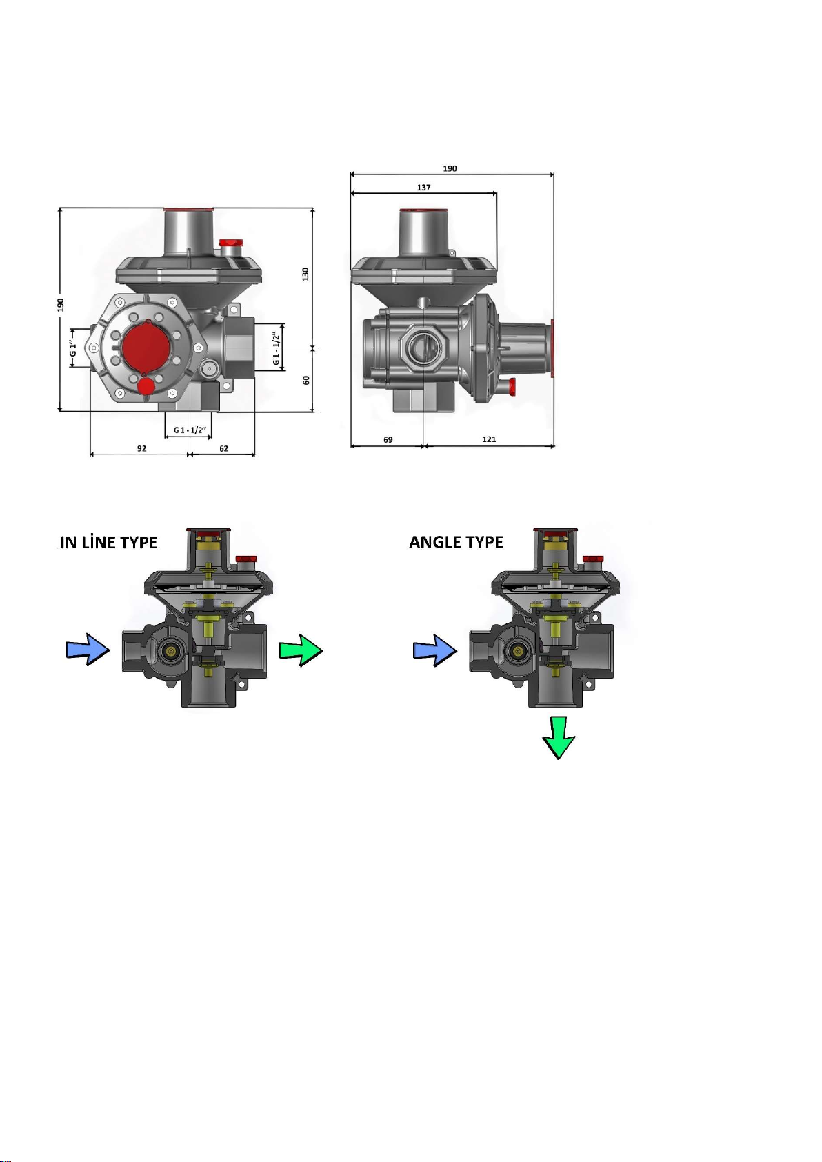
Connection: Inlet DN25 threaded, outlet DN32 threaded (modular connection up to DN50 on request),
Operating Temperature Range: -10 ° C; 60 ° C or -20 ° C; 60 ° C or (LT version on request -40 ° C to 60 ° C)
Line Connection Directions: Inline Type and Angle Type
Accuracy Class - Output Pressure Tolerance: AC5 / AC10
Output Pressure Setting Range (Wd): 15-360 mbar
High Pressure Safety Closure Setting Range (Wdo): 35-520 mbar
Low Pressure Safety Closure Setting Range (Wdu): 8-250 mbar
Working Pressure Range (bpu): 0,5-6 Bar
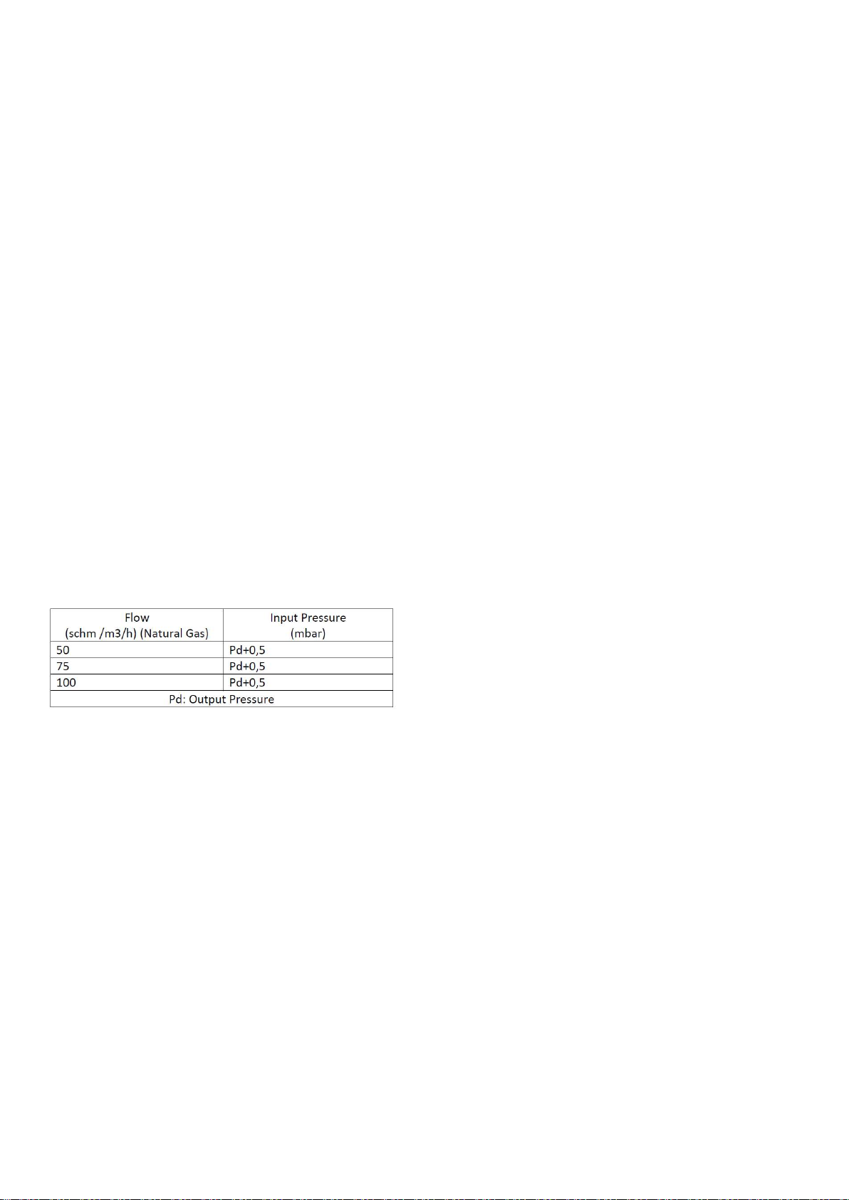
Min and Maximum Flow (Qmin-Qmax): 5 m3/h – 100m3/h (Natural Gas)
Flow Rate Parameters:
Natural gas is converted to LPG by multiplying by 1,2

4
Material Standards: Aluminum EN 1706, Rubbers EN 549, Brasses EN 12164-EN 12165
Figure – 3
3-MOUNTING
Determine which features should be used before mounting, and check that the correct selection is made by examining the
pressure and other information on the product label, especially with regard to labeling and labeling information, check the
product and accessories that may be on the box Input filter, way shut-off protective lid no.1, if equipped, protective tapes,
if available, pressure set seals no.4) (Working pressure range, outlet pressure, fluid, flow rate, environmental conditions,
clean line and fluid, selection of reciprocal connection type and diameter, compatibility of line and product dimensions
etc.)
There must be an inlet and outlet shutdown valve before and after the regulator to be installed. Ensure that there is no
pressurized gas trapped between the line and the product before and during mounting, and that the gas supply is
completely covered and opened. Before mounting, it should be checked that the line pressure is within the inlet pressure
range stated on the product label and that the regulator capacity will not be exceeded during use. Sufficient tampon
volume should be left at the line outlet after the regulator before assembly. For products with outlet pressures of up to
300 mbar, 1/500 nominal flow and 1/1000 nominal flow at outlet pressures above 300 mbar are recommended. Necessary
precautions should be taken to avoid sound and vibration from the line. It should not even be misplaced. Clamp on the
line side to reduce the torsional and torsional loads from the pipeline and the shake at the line inlet and outlet before
mounting etc. Take appropriate precautions by means of roads, even at short distances at the entrance and exit of the
product, make sure that there are no diameter reductions and expansions, testing, maintenance, dismantling etc. Ensure
that the required dimensions and areas are ensured by considering the subsequent operations, in each case check that
the product inlet pressure is higher than the product outlet pressure, clean the inside of the pipe with compressed air
when the product is not yet installed and the welding particles, dirt etc. Remove foreign objects, generally check the line
and system for pressure and tightness, ensure that the external filter is installed before the gas pressure regulator to filter
5
the gas, ensure that the products are directly exposed to external environment and external corrosion conditions (sun,
rain, snow, humidity, water, Etc.) with the necessary precautions so that they are not exposed to any external damage and
impact (e.g. into the protective box)
To start the mounting; manually remove the input-output connection protection tapes, if the additional modular
connection is present, manually insert the molded input and output seals into the input and output connection ports
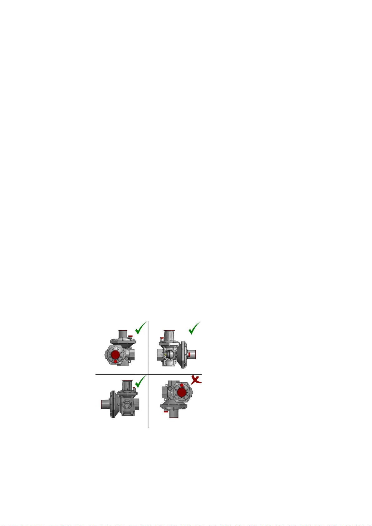
(always use approved and new gaskets) and set the flow direction of the product so that the gas flow direction is indicated,
the product mounting position does not look at the side where the outlet pressure adjustment part for dry gases is located.
An example of the vertical position in the horizontal direction by the slit is as shown in figure 1 and the flow lpg is the
downstream side of the regulator , ensure that the assembly components to be used during assembly comply with the
regulations and that the product will not be obstructed by the product or even the manual overload, and do not expose
the mechanical strut, tighten it as tightly as you can to ensure that the inlet and outlet connections of the product do not
leak outside without applying excessive force, force or impact using appropriate switches. After tightening, it is fully seated
in the groove of the connections and there is no cracking in the connections. check that there are no mechanical problems
and that there is no mechanical stress from the line, pipe and connector.
If fittings with a connection greater than the diameter of the connection on the product's body are to be fitted to the inlet
and outlet of the product for assembly, the forces and moments which are exceeded by the main connection diameter on
the body shall not be applied and the limitations should not be applied.
If the products are to be used in floor type applications, make sure that the products coated on the outer surface are used
properly. Appropriate precautions should be taken to prevent entry and also ensure that products are not used completely
in water or liquids. The exhaust line should be connected to the breathing console of the regulator when necessary. This
connection must be at least DN10 threaded. The threaded adapter that may be needed for this connection is required and
must be used. Gas pressure regulators with discharge system are required measures to transport the gas to be delivered
to the safe zone (e.g. at least DN 10 pipe to the outside atmosphere conditions of the gas to be evacuated) If the products
are to be used in floor type applications, make sure that the products coated on the outer surface are used properly.
Appropriate precautions should be taken to prevent entry and also ensure that products are not used completely in water
or liquids. The exhaust line should be connected to the breathing console of the regulator when necessary. This connection
must be at least DN10 threaded. The threaded adapter that may be needed for this connection is required and must be
used. Necessary precautions must be taken to move the gas pressure regulators, which are discharge systems, to the safe
zone of the gas to be evacuated. (E.g. a pipe of at least DN 10 to the outside atmosphere conditions of the gas to be
evacuated)
Figure-1

6
4-INSTALLATION, TRANSMISSION AND OPERATION
Before installation, check and make sure that all users and persons at the outlet are not in use, do not change the factory
settings. The factory settings are adjusted according to the desired values in the order specifications and are stated in the
model. The adjustment devices are sealed if requested in the order specification.
To start the installation; partially open the outlet valve on the line, slowly open the inlet valve on the line gradually, remove
the protective cover 11 by turning it clockwise by hand, in this case, 22 lightly pull the set-up without manually applying
excessive force, force and impact, verify that there is a gas flow at the outlet side for a few seconds while pulling it, pull
the set-up slightly further and then release slowly so that the product will be set up. If installation does not occur, repeat
the procedure. Once the installation has taken place, replace the protection cover 11 with the cover 22, in which case the
installation path 11 will move forward with the protection cover 11, which will not adversely affect the installation.
(Installation process figure-6).
If you encounter difficulty in pulling the 22-bolt-up bar during installation and encounter the closure of the bolt-hole,
opening of the inlet valve at a very small amount, not a full amount, allowing a small amount of gas out of the test nipple
in the outlet line. You can process transactions after processing nipple test. Replace parts.
After the product has been installed, the gas flow is at the exit, the gas line 22 is in the installed position, the gas can be
mixed into the atmosphere and the gas leakage can be detected by suitable foam, detector etc. check with the gauges,
inform the gas users about the gas usage.
Depending on the temperature difference during the set-up process or seasonal transitions, there may be momentary gas
outflow from the product discharge and this is normal. It is important that the gas output does not continue, and if it
continues, it may be considered a malfunction
If the installation process does not work, please go with us
After the installation;
For testing outlet pressure, high pressure shutoff, low pressure shutoff, discharge functions;
First of all, take all necessary precautions to prevent dangerous atmosphere on the side of the evacuation gas that may be
formed from the regulator before all the following operations and do not work in closed areas
Connect the pressure gauge and pressure source to the appropriate test valve on the outlet line of the regulator with a
tight seal. When the gas consumption is present in the regulator line, check the outlet pressure and check the
appropriateness within the tolerances. Close the outlet valve at the outlet of the regulator and wait for a while, and check
that the outlet pressure is stable and that the value is within tolerance.
Slowly increase the pressure in the pressure source and verify that the product is evacuating at the correct pressure. Slowly
increase the pressurized high pressure in the pressure source to the safety shut-off setting and check that the shut-off set-
up 22 is closed. Then reinstall the device, then close the inlet valve and reduce the pressure source under the pressure
outlet, and verify that the product automatically turns itself off.
Disconnect the pressure source, close the test valves, check that there are no external leaks on the line, and replace the
device by following the rules in this order

7
If the gas pressure regulator is closed for various reasons during operation, the inlet valve must be closed, the problem
must be identified and reinstalled according to the above rules. During the operation, the gas is not clean and the internal
leak due to the foreign objects on the line, obstruction of the breathing line, product failure etc. the outlet pressure can
increase due to the situation and the gas can be cut off by closing the product high pressure safety shutdown device.
During operation, if the outlet pressure of the regulator drops due to various reasons and reaches the set safety pressure,
the low pressure safety shut-off system will be activated and the gas passage can be closed. In either case, the product 22
maintains the starting position of the shut-off installation. In either case, the installation process must be re-established.
Note: In no case shall the operation of the product be caused to pass over to the inlet opening of the inlet opening of 6
bar and the outlet opening of the product to a pressure of more than 0.6 bar over the top cover, and this shall not be
allowed to ocur
Figure -6
5-PARAMETERS
For various reasons, if necessary, the product outlet pressure and safety shutdown pressure settings should be made as
follows.
The settings should not be changed by more than ± 10% and not beyond the limitations on the label.
The seals are removed if the product has the relevant setting parts. When pressure settings are made, the setting
mechanisms and springs should not be over-tightened or forced. To see the values of the settings, connect the pressure
gauge or manometer to a suitable test valve between the regulator and the outlet pipe. In all adjustments to be made, the
pressure increase in the clockwise rotations is reversed and the pressure decrease in the opposite directions. When the
outlet pressures are increased, the safety pressures must also be increased.
To change the output adjustment pressure; Remove the relevant seal if necessary, remove the way cover no.1 manually
by turning it counterclockwise; turn the adjustment ring 2 with the 27 mm hex key in the appropriate direction, mark the
adjustment pressure made.
To change the high pressure safety pressure; Remove the corresponding seal if necessary, remove the turn cover no.11
manually by turning it clockwise; turn the way adjuster ring no.13 in the appropriate direction with the 27 mm hex key,
mark the adjustment pressure made.

8
To change the low pressure safety pressure; Remove the relevant seal if necessary, remove the 11-way cover manually by
turning it clockwise; turn the 12-way adjuster ring into the appropriate direction with the 13 mm hex key, mark the set
pressure. Mark the adjustment pressure made.
After the setting changes made, please check with the appropriate methods in this manual that the specifications and
limits on the product are not exceeded. It is recommended that the setting devices be sealed after the relevant pressure
settings have been made or in order to ensure that the settings are not changed in the products for which usage has been
made. If this is the case, the seal inside the box can be used.
6-PERIODIC MAINTENANCE AND INSPECTION
Periodic maintenance-inspection period for healthy and safe operation of the regulator. Periodic maintenance-monitoring
intervals. To adjust the maintenance time according to the operating conditions.
The rules in this instruction must be complied with in all transactions. In no case do not discharge suddenly to clean the
line after the regulator or to make maintenance-inspection of the product.
For periodic care; Disconnect the product from the line in accordance with the dismantling rules in this instruction. If there
are, manually remove the seals on the inlet and outlet connections side and replace with new ones. Take out the cover
screws no 20 and 23 on the regulator with suitable tools in a way that there will be no contraction and remove the covers
manually. (If there is a paint, lacquering, etc. seal on the cap screws, do not perform these operations and maintenance,
send the product to our company) Do not disassemble the parts inside the covers that you have removed, keep the covers
as a group and clean them gently with a clean cloth.
22 by pulling the money by hand, raising the 17-up part, then 22-part then 17-part. Remove the 24-way screws and remove
the 9-way filter, replace it at the side, change the color in your color.
After changing the filter, using the same screws number 20 and 23, fix the screws to the same places by mutual tightening
without excessive force so that the screws will not contract and the holes are overlapped, make sure that it is not loose
and mechanically damaged. Assemble and install the product whose maintenance has been completed, according to this
instruction.
In no case do not perform maintenance operation while the product is on the line.
For periodic examination; Check that the inlet and outlet valves are open and there is pressure at the outlet. Suitable foam,
liquid, detector etc. Using methods, look at all external parts of the product, including connections, and check that there
is no external leakage and that there is no excessive noise and vibration in the line and the product. In addition, review
the "Output pressure, high pressure shutdown, low pressure shutdown, test of relief functions" described in the
installation section of this instruction, taking all relevant safety precautions.
After the relevant maintenance and inspection procedures, shut-off protection cap no.11, pressure adjustment seals, if
any, drain protection plug no.4, drain filter no.21 etc. Check that all accessories and apparatus are attached to the product.
Note: In all cases, make sure that the necessary lines are opened to the atmosphere, since there is not and will not be in a
closed area in all cases that may cause gas to exit from the product or the line.
If a problem is detected during periodic maintenance and inspection, necessary actions can be performed according to the
rules described in the breakdown section.

9
7-DISCONTINUE, REMOVAL AND REPLACEMENT
Before, during and after all disassembly and replacement, please observe all the rules and procedures required in this
manual. We ensure that there is no pressurized gas trapped between the line and the product before the dismantling and
replacing operations and also the product during the dismantling process, the gas supply is completely closed and the
possibility of opening is ensured.
Close the inlet and outlet valve on the line at the front and rear of the regulator and reliably discharge the trapped gas
between the line and the product, gradually from the area between the gas pressure regulator and the outlet valve. Do
not swing the input and output connections of the product without using excessive force and force using the appropriate
switch. If a new product is to be replaced, install and install the new product in accordance with this instruction.
Table-1
Problems and
Solutions
Proble
m
Code
Problem Transaction codes that will be performed In
order
P1 Dirty filter 10,11
P2 Self-organization 12,1
P3 Mechanical damage 1
P4 Failure in drying 13,9,25,1
P5 No gas flow 26, 3,14,15 ,16,18,10,11,5,2,4,25,1
P6 External leakage 16,18,1
P7 High exit pressure except tolerances
8,7,2,1
P8 Low exit pressure except tolerances
16,18,5,6,3,2,1
P9 Evacuation system mistakes 7,8,2,1
P10 Insufficient flow 3,10,11,4,2,1
P11 Shut-off mistakes 19,27,Measure the output pressure and
control that it is increasing, if it is, apply transactions
no.7,8,2. 20,21,25,1
P12 Missing accessory 23
P13 Sound and Vibration 24
8-TROUBLE-REPAIR-PROBLEMS AND SOLUTIONS
Before, during and after all breakdown procedures, please obey all the rules stated in this manual as necessary and take
necessary actions, especially inform the end users and take necessary precautions against pressure gas hazards.
In case of failure you are advised to perform the operations indicated in Table 1 according to the type of problem and if
you do not wish to do these operations and if you have not resolved the problem in question then you should remove the
product and disassemble the product according to the disassembly rules described below without further intervention, ,
Even install new products. Repairs, repairs and alterations shall not be made in such a way as to interfere with the internal
parts of the product other than the filter and spring change.
Repairs and repairs should be done in empty systems and products removed from the line.

10
9- DIMENSIONS, LINE CONNECTIONS AND PART INFORMATION
Dimensions are in mm
Table 1
Transaction Codes Explanations that can be applied with sequence during problem
1-New product exchange
2-Measure the output adjustment pressure and correct if it is faulty
3-Check that the wrong product is not selected as the flow rate and outlet pressure
4-Check that the inlet pressure is not below the pressure and the inlet pressure
5-Have traction on the capacity of the product check
6-Examine external leakage at the output line
7-Check that there is no excessive diameter contraction in the output line
8-Stop the gases flow at the outlet, close the inlet valve, then open it, re-engage the product and check the result
9-Remove and reattach the product and try again
10-Remove the product, remove and clean the filter, attach a new filter if necessary, mount the product back on the line.
11-Take precautions for line cleanliness
12-Confirm whether or not the product has automatic installation system
13- Check if the shut-off arm no.2 is closed, if it is closed check that there is no excessive contraction in the line outlet and
hold the way shut-off arm no.2 by holding the handle while continuing the installation, if necessary, loosen the removing
protection cover no.14, relieves the valve a bit, relieves the pressure squeeze out instantaneously, and then restore all
operations
14- Set up shut-off no.2 if the door is closed, replace the product and check the result
15- Check whether there is freezing in the water or in the water that might enter the product
16- If there is loose screw, check it regularly according to rules. (Do this if there is a seal on the screw)
18- If there is a leak from the outlet, check that there is no excessive diameter contraction on the outlet line. If there is no
problem, stop the outlet gas outlet, close the inlet valve.
19- Check whether there is traction and inclination in set up shut-off line the arm.
20- Check that there is no contraction in the output sensing line.
21-Adjust the shut-off setting pressure and correct if it is faulty.
23- Shut-off protection cap, if available pressure setting seals, if available way discharge protection plug no.14, if available
way discharge filter no.15 etc. Identify the missing pieces and insert the new ones manually.
24- Is the mounting position correct, whether there is fluctuation in the input pressure, the diameter at the close distance
on the output side is not wanted. Check for shrinks.
25- Try to install the product again.
If the 26-2 shut-off line is closed, inform all interested parties, ensure that no gas is used, and re-install the product in
accordance with the rules.
27- Flow in the outlet boiler, etc. Check if there has been a pressure increase due to sudden stop.
11
Figure-2
Figure-4
12
Figure-8
10-LABEL INFORMATION
Pds: Output Setting Pressure
Pdso: High Pressure Safety Closure Setting Pressure
Pdsu: Low Pressure Safety Closure Setting Pressure

13
Pdso: Evacuation Pressure
TS: Working Environment Temperature Range
PS: Maximum Resistance Pressure
Pumax: Maximum Input PressurePSD : Farkli Dayanimli Kisimlar İçin Maximum Dayanım Basıncı
PSD: Maximum Strength Pressure For Different Resistant Parts
Bpu: Input Pressure Range
DN: Connection Diameter
Qmin-Qmax: Minimum and Maximum Flow
Wd: Output Pressure Setting Range
Wdo: High Pressure Safety Closure Setting Range
Wdu: Low Pressure Safety Closure Setting Range
NG-LPG: Natural Gas-LPG
11-STORAGE-STORAGE-LIFTING-LOWERING-MOVE-LOADING-TRANSPORT
Do not remove the product from its original box and their sleeves unless the use is started, do not change the box and its
sleeve. Store the products and spare parts in closed and ventilated environments in clean room conditions. Ensure that
during transport, transportation and storage, products are exposed to rain, water, snow, extreme heat and cold. You are
protected from the circumstances. Ensure that the floors where the operations are made are flat and clean, not wet and
slippery. Do not overload and remove during transport. Pay special attention to external protrusions and external parts.
14
EU DECLARATION OF CONFORMITY
AB UYGUNLUK BEYANI
According to Pressure Equipment Directive (2014/68/EU)
Basınçlı Ekipmanlar Yönetmeliği’ne Göre (2014/68/AB)
Declaration Number
(Deklarasyon No)
DEC_012_R00
Manufacturer and Owner Of Certificate
(Üretici ve Sertifika Sahibi Adı)
ESKA VALVE A.Ş.
Trade Mark
(Ticari Marka)
ESKA VALVE / ESKA
Manufacturer Adress and Place
(Üretici Adresi ve Üretici Yeri)
Sakarya 1. Organize Sanayi Bölgesi Mahallesi, 11. Cadde, No:6-8,
Arifiye/Sakarya/Türkiye
Product Description
(Ürün Tanımı)
Gas Pressure Regulator With Safety Shutoff Valve
Emniyet Kapatmalı Gaz Basınç Regülatörü
Product Model / Type / Serie
(Ürün Modeli / Tipi / Seri)
ERG-SR Series
ERG-SR Serisi
Product Information
(Ürün Bilgileri)
PS6, PSD0.6 , TS: -10;60°C , -20;60°C , (LT version -40;60°C) , DN25xDN40
Threaded Connection (on request modular connection) , AC 5/10, SG 10/20/30, AG
10/20
PS6, PSD0.6 , TS: -10;60°C , -20;60°C , (LT versiyon -40;60°C) , DN25xDN40 Dişli Bağlantı
(istek üzerine modüler bağlantı) , AC 5/10, SG 10/20/30, AG 10/20
Declaration Issue Date
(Deklarasyon Yayın Tarihi)
01.11.2020
The name of the Notified Body and No
(Onaylanmış Kuruluşun Adı ve Numarası)
TÜV SÜD Industrie Service GmbH – 0036
WestendstraBe 199 80686 München/Germany
EU Conformity Assessment Method
(AB Uygunluk Değerlendirme Yöntemi)
2014/68/EU PED Category IV, Modul B+D
Modul B Certificate No / Valid Until
Modul D Certificate No / Valid Until
07/202/9280/Z/0040/18/D/0062 / 24.01.2028
07/202/9280/Z/0088/18/D0062 / 22.02.2021
Declaration
(Deklarasyon)
Up defined in our products, we declare that meets the essential safety requirements of the directives
to in this document. This declaration of conformity has been published under the responsibility of
Eska Valve A.Ş.
Yukarı da tanımlanan üzerinde seri no olan ürünlerimizin, bu belgede belirtilen yönetmeliklerin
temel güvenlik gerekliliklerini karşıladığını beyan ederiz. Bu uygunluk beyanı Eska Valve A.Ş. nin
sorumluluğu altında yayınlanmıştır.
Note
(Not)
The compliance with Directives applies only to the product if the product is integrated in a system
or combined with other units .The system manufacturer is responsible fort he compliance of the
complete system with Directives. By altering the device without approval the declaration would
invalidate.
Ürünün bir sistemle entegre olarak ya da diğer bir birimle birleştirilerek kullanıldığı durumlarda
direktiflerle uyumluluk yalnızca ürünü kapsar. Sistem üreticisi sistemin tamamının direktiflere
uyumluluğundan sorumludur. Onayımız alınmadan cihaz üzerinde değişiklik yapıldığında bu
beyan geçerli değildir.
Manufacturers Authorized Signature
(Üretici İmza Yetkilisi)
Erhan SARDAL
General Manager (Genel Müdür)
Sakarya/Türkiye, 01.11.2020

15
WARRANTY CERTIFICATE
The Manufacturing Company's;
Title: ESKA VALVE A.Ş.
Address: Sakarya 1. Organize Sanayi Bölgesi Mahallesi, 11. Cadde, No: 6-8, Arifiye/Sakarya/Turkey
Telephone : +90 (264) 502 54 34-35
Fax : +90 (264) 502 54 84
E-mail : info@eskavalve.com
Authorized Signature:
Company Stamp:
The Vendor's;
Title:
Address:
Telephone:
Fax:
E-mail:
Authorized Signature:
Company Stamp:
The Product's;
Type: Gas Pressure Regulator
Brand: ESKA / ESKA VALVE
Model-Series: ERG-SR
Warranty: 2 years
Maximum Time To Repair: 20 business days
Invoice Date and Number:
Date of Delivery to the Consumer:
Place of Delivery to the Consumer:
Banderole and Series Number:

16
TERMS OF WARRANTY
1) The warranty period starts with the delivery of the product and is 2 years.
2) The entire product, including all parts thereof, is covered by the warranty.
3) In such cases where the replacement of the defective goods by those free of defects would cause disproportionate challenges
to the Seller, the Consumer shall be entitled to either rescission of the agreement or a discount over the sales price in proportion
to such defects thereof. For determination of disproportionality, factors such as the value of the goods free of defects, the severity
of the defect, and whether resorting to other rights of choice would constitute any problem for the Consumer are taken into
consideration thereof. In cases where the Consumer chooses rescission of the agreement or a discount over the sales price in
proportion to such defects, the Seller shall be obliged to refund the Consumer the sales price of the goods in full or the discount
amount as applicable without delay. In case the Consumer chooses the replacement of the defective goods by those free of
defects, then the Seller, the manufacturer, or the importer shall be obliged to fulfill such a request within thirty (30) business
days from the date of notification for the replacement of such defective goods by those free of defects thereof.
4) In case the Consumer chooses the repair of the goods free of charge, among such other options, then the Seller shall be obliged
to perform or cause to perform the repair of such defective goods without any claim for workmanship cost, cost of replaced parts,
or any other cost or expense under any title whatsoever. The Consumer may also exercise its right of repair free of charge against
the manufacturer or importer thereof. The Seller, the manufacturer, and the importer shall be jointly and severally liable for the
Consumer to exercise such rights thereof.
5) In the case that the Consumer uses the right to receive free repair, if the product breaks down again within warranty period, -
if the maximum time provided for repair is exceeded, - if the authorized service station, Seller, manufacturer or importer
determines with a report that repair is not possible; the Consumer can request the refunding of the price paid for the product,
or price discount at the rate of the defect, or, if possible, replacement of the good with a faultless equivalent. The Seller cannot
reject such request of the Consumer. If this request is not fulfilled, the Seller, manufacturer and the importer are jointly and
severally responsible.
6) The maximum period of repair of defective goods is 20 business days. Such period commences on the date of notification of
the relevant defects in the goods to the service station or the Seller within its warranty period, or otherwise, upon delivery of the
defective goods to the service station in case the warranty period of the goods has expired. In case of any defects in the goods
within the warranty period, the repair period is added to the warranty period thereof. It is mandatory to determine whether such
defects are attributable to misuse by the Consumer by a formal report to be issued by the service stations, or otherwise, in case
such service stations are not available, by the Seller, the importer, or the manufacturer of the goods, respectively, as applicable
within the maximum period of repair of the goods, and provide the Consumer with a copy of such report thereof. The warranty
period of the replaced goods under warranty shall be limited to the remaining warranty period of the originally purchased goods
thereof.
7) The defects caused by usage of the product against the provisions of the user’s manual and failures caused by usage errors are
not covered by warranty.
8) The Consumer shall be entitled to refer to the Consumer Arbitration Committee or the Consumer Court of the Consumer’s
residence or of the jurisdiction where consumer proceedings take place in case of any disputes arising out of or in relation to
exercising the rights under such warranty thereof.
Table of contents
Other ESKA Controllers manuals


