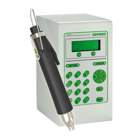
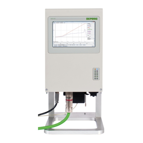
Deprag AST6 User manual

013735en
Operating Instruction Booklet
- Translation of the original instruction -
Sequence Controller
AST6 428001 A
NOTICE ALLDOCUMENTATIONS !
Before beginning work this operating instruction booklet and the enclosed
safety instructions (no. 016000, pink-colored booklet) have to be read through
carefully. Always follow the instructions during operation. Give this operating in-
struction booklet and the appropriate safety instructions to the operator.

2
Contents
1DEFINITION OF SIGNAL WORDS AND SYMBOLS................................................................. 6
2SAFETY INSTRUCTIONS.......................................................................................................... 7
3INTENDED USE ......................................................................................................................... 7
4SCOPE OF DELIVERY............................................................................................................... 8
5SHORT DESCRIPTION.............................................................................................................. 8
6HARDWARE DESCRIPTION..................................................................................................... 9
6.1 Views of the AST6 ................................................................................................................... 9
6.1.1 Front Panel ........................................................................................................................... 9
6.1.2 Connection Panel.................................................................................................................. 9
6.2 Interface Description .............................................................................................................. 10
6.2.1 Screwdriver ......................................................................................................................... 10
6.2.2 Voltage Supply .................................................................................................................... 10
6.2.3 Ethernet .............................................................................................................................. 10
6.2.4 Input/Output Interface ......................................................................................................... 11
6.2.5 Interface Fieldbus (optional)................................................................................................ 11
7COMMISSIONING.................................................................................................................... 12
7.1 Dimension Sheet.................................................................................................................... 12
7.2 Assembly Instruction .............................................................................................................. 13
7.3 Information on programming the Sequence Controller .......................................................... 14
7.4 Functioning of the Sequence Controller AST6....................................................................... 14
7.5 Connection to a master controller .......................................................................................... 15
7.5.1 I/O Interface ........................................................................................................................ 15
7.5.2 Fieldbus modules (optional)................................................................................................ 15
8OPERATION............................................................................................................................. 24
8.1 General .................................................................................................................................. 24
8.2 Operating via the Touch Display............................................................................................ 24
8.2.1 Control Elements................................................................................................................. 24
8.2.2 Menu Structure.................................................................................................................... 27
8.2.3 Description of the Menu Structure....................................................................................... 28
8.3 Operation via the Web Interface ............................................................................................ 32
8.3.1 Requirements...................................................................................................................... 32
8.3.2 Preparing to use the Web Interface .................................................................................... 32
8.3.3 The Menu Structure ............................................................................................................ 33
8.3.4 Description .......................................................................................................................... 34
9SETTINGS................................................................................................................................ 50
9.1 Description of the adjustable Prameter.................................................................................. 50
9.1.1 General Parameters............................................................................................................ 50
9.1.2 Special parameters for fieldbus systems (optional) ............................................................ 51
9.2 Default Values........................................................................................................................ 52
9.2.1 General Parameters............................................................................................................ 52
9.2.2 Special parameters for fieldbus systems (optional) ............................................................ 52
10 SCREWING SAMPLES AND COMMANDS........................................................................... 53
10.1 Screwing Sample .................................................................................................................53
10.1.1 Screwing / loosen to Torque ............................................................................................. 53
10.1.2 Expanded screwing to torque............................................................................................ 54
10.1.3 Screwing / loosen to angle................................................................................................ 55
10.1.4 Friction Value Package (optional) ..................................................................................... 57
10.2 Commands........................................................................................................................... 63
10.2.1 Waiting for input ................................................................................................................ 63
10.2.2 Setting the output..............................................................................................................63
10.2.3 Resetting the output.......................................................................................................... 63
10.2.4 Display Values ..................................................................................................................63

3
10.2.5 Save Values ...................................................................................................................... 63
10.2.6 Statistic ............................................................................................................................. 63
10.2.7 Waiting Time ..................................................................................................................... 63
10.2.8 Hold Position..................................................................................................................... 63
11 DIAGNOSIS............................................................................................................................ 64
11.1 System Test ......................................................................................................................... 64
11.2 Screwdriver Test .................................................................................................................. 64
11.2.1 Number of Rotation Test................................................................................................... 64
11.2.2 Angle Test......................................................................................................................... 64
11.2.3 Torque Test....................................................................................................................... 64
11.3 Sequence Test..................................................................................................................... 65
11.4 Interface ............................................................................................................................... 65
11.4.1 I/O Interface ...................................................................................................................... 65
12 DOCUMENTATION................................................................................................................ 66
12.1 Final Values ......................................................................................................................... 66
12.2 Curve Representation .......................................................................................................... 67
12.3 Statistic ................................................................................................................................ 68
13 MAINTENANCE AND SERVICING........................................................................................ 69
13.1 Updating the Software ......................................................................................................... 70
13.1.1 Main Control and Touch Display....................................................................................... 70
13.1.2 Power unit ......................................................................................................................... 70
13.1.3 Calibrating the Touch Display ........................................................................................... 70
13.2 Exchanging the Battery........................................................................................................ 71
13.3 Spare Parts .......................................................................................................................... 71
14 ERROR DISPLAY AND TROUBLESHOOTING .................................................................... 72
14.1 System Errors ...................................................................................................................... 72
14.1.1 Screwdriver ....................................................................................................................... 72
14.1.2 Power Unit ........................................................................................................................ 72
14.1.3 Main Controller.................................................................................................................. 73
14.1.4 Communication ................................................................................................................. 73
14.1.5 I/O Interface ...................................................................................................................... 74
14.2 Error in the Screwing Sequence .......................................................................................... 75
15 TROUBLE SHOOTING........................................................................................................... 76
16 REQUIRED ACCESSORIES.................................................................................................. 77
16.1 Power Cable ........................................................................................................................ 77
17 OPTIONAL EQUIPMENT....................................................................................................... 77
17.1 AST6 to PC connecting Cable ............................................................................................. 77
17.2 Fieldbus Module................................................................................................................... 77
17.2.1 Profibus............................................................................................................................. 77
17.2.2 Profinet.............................................................................................................................. 77
17.2.3 Ethercat............................................................................................................................. 77
17.2.4 Ethernet IP ........................................................................................................................ 77
17.3 Base..................................................................................................................................... 77
17.4 Plug Connector 24V Input/Output Interface ......................................................................... 78
17.5 Plug Connector Voltage Supply ........................................................................................... 78
17.6 Touch-Pen ........................................................................................................................... 78
17.7 Optional Software Packages................................................................................................ 79
17.7.1 Friction Value Software Package...................................................................................... 79
17.7.2 DataLogger ....................................................................................................................... 79
17.7.3 GRAPH10 - Curve overlapping......................................................................................... 80
18 DECOMMISSIONING AND STORAGE.................................................................................. 81
19 TECHNICAL DATA ................................................................................................................ 82
20 GLOSSARY............................................................................................................................ 83
21 EC DECLARATION OF INCORPORATION .......................................................................... 87

4
22 SERVICE LOCATIONS AND AUTHORIZED PARTNERS.................................................... 88
List of figures
Figure 1: Front Panel of AST6 ....................................................................................................... 9
Figure 2: Connection Panel of AST6.............................................................................................. 9
Figure 3: Dimension Sheet........................................................................................................... 12
Figure 4: Main Screen: Process Display...................................................................................... 14
Figure 5: Hardware configuration of Profibus DP......................................................................... 16
Figure 6: Hardware configuration of Profinet ............................................................................... 16
Figure 7: Selecting between two Options..................................................................................... 25
Figure 8: Selecting between several Options............................................................................... 25
Figure 9: NumericalBlock for numerical Input .............................................................................. 26
Figure 10: Keyboard for Text Input .............................................................................................. 26
Figure 11: Menu Structure ........................................................................................................... 27
Figure 12: Main Menu .................................................................................................................. 28
Figure 13: Process Data Menu .................................................................................................... 29
Figure 14: Curve display .............................................................................................................. 29
Figure 15: Menu System.............................................................................................................. 30
Figure 16: Screwing Sequence .................................................................................................... 30
Figure 17: Test Menu ................................................................................................................... 31
Figure 18: Web Interface Menu Structure.................................................................................... 33
Figure 19: The Home Page.......................................................................................................... 34
Figure 20: Start page ................................................................................................................... 35
Figure 21: Statistic .......................................................................................................................36
Figure 22: Downloading Curve Data ............................................................................................ 37
Figure 23: Screwdriver Results.................................................................................................... 38
Figure 24: Tool Data .................................................................................................................... 39
Figure 25: System Data ............................................................................................................... 40
Figure 26: Update ........................................................................................................................ 41
Figure 27: Activating Extensions.................................................................................................. 41
Figure 28: Default Settings .......................................................................................................... 43
Figure 29: Default Settings - Lower Part of the Page................................................................... 43
Figure 30: Date / Time ................................................................................................................. 44
Figure 31: New Password ............................................................................................................ 44
Figure 32: Screwing Sequence .................................................................................................... 45
Figure 33: Manuals ...................................................................................................................... 48
Figure 34: Additional Programs.................................................................................................... 49
Figure 35: Fieldbus ...................................................................................................................... 49
Figure 36: Screwing Application to torque ................................................................................... 53
Figure 37: Expanded screwing to Torque .................................................................................... 54
Figure 38: Screwing to Angle....................................................................................................... 55
Figure 39: Loosening on Angle .................................................................................................... 56
Figure 40: Friction Value Measurement....................................................................................... 57
Figure 41: Screwing on differential Torque .................................................................................. 58
Figure 42: Screwing Applications depending on Friction ............................................................. 60
Figure 43: DataLogger ................................................................................................................. 79
Figure 44: GRAPH10E................................................................................................................. 80

5
List of tables
Table 1: Modules and UDT's for the control................................................................................. 17
Table 2: Directory of the modules ................................................................................................ 17
Table 3: Description - Interface parameters (FB13)..................................................................... 18
Table 4: Description – Data structure of the control signals (UDT31).......................................... 19
Table 5: Description – Data structure of the status signals (UDT32)........................................... 21
Table 6: Description – Error Codes.............................................................................................. 21
Table 7: Description – Data structure of the screw data (UDT33) ............................................... 22
Table 8: Adjustable Parameter .................................................................................................... 51
Table 9: Configurable Profibus parameters ................................................................................. 51
Table 10: Configurable Profinet parameters ................................................................................ 51
Table 11: Configurable Ethernet IP parameters........................................................................... 51
Table 12: Default Values.............................................................................................................. 52
Table 13: Default values for Profibus........................................................................................... 52
Table 14: Default values for Profinet............................................................................................ 52
Table 15: Default values for Ethernet IP ...................................................................................... 52
Table 16: Structure of the Data Set.............................................................................................. 66
Table 17: System errors regarding the screwdriver ..................................................................... 72
Table 18: System errors regarding the power unit ....................................................................... 72
Table 19: System errors regarding the main controller ................................................................ 73
Table 20: System errors regarding the communication ............................................................... 73
Table 21: System errors regarding the I/O interface .................................................................... 74
Table 22: Fault in the Screwing Sequence .................................................................................. 75
Table 23: Troubleshooting ........................................................................................................... 76

6
1 Definition of Signal Words and Symbols
The signal words and symbols used in the technical documentation (safety instructions,
operating instruction booklet, et c.) have the following meaning:
DANGER
Indicates an immediate danger which causes serious injuries or even
death if not avoided.
WARNING
Indicates a threatening danger which can cause serious injuries or even
death if not avoided.
CAUTION
Indicates a danger or unsafe procedure which can cause injuries to a per-
son or material damages if not avoided.
NOTICE
Indicates a potentially dangerous situation which can cause damage to
the product or its surroundings if not avoided.
IMPORTANT
Indicates tips and other useful information.
In each case the symbol used does not replace the safety text. The text must always be
read full
y
. In some cases other s
y
mbols will be us ed with the si
g
nal words.

7
2 Safety Instructions
Reading the enclosed safety instruction booklet no. 016000 (pink-coloured booklet) is
essential for working with the equipment.
WARNING
Fires, electric shocks and other injuries, or damages to components can be
caused if the safety guidelines are ignored.
WARNING
Risk of fatal injury due to electrocution!
Disconnect the electric equipment from the power supply before starting
any wor k on the tool (e.g. installation, changing of accessories or machine
tools, removal of covers prior to longer downtimes, maintenance works,
etc.).
Switch off the mains switch and pull out the mains plug!
3 Intended Use
The sequence controller AST 6 is designed exclusively for fittings in industrial use. And
must only be operated with DEPRAG MICROMAT®–EC screwdrivers (stationary) of the
series 320E12 and 320E19.
The system is especially suitable for application requiring the highest demand of quality,
flexibility and documentation.
Use beyond its intended use is considered unauthorized and therefore improper.
Furthermore, DEPRAG is not liable for damage resulting from the misuse of the
instrument; the user alone is liable.
The correct use of the instrument includes compliance with all operating, maintenance and
repair instructions.
IMPORTANT
Please contact your DEPRAG Representative, our international service
centers or contact DEPRAG SCHULZ GMBH u. CO. directly if you have
any questions.
Visit our website at www.deprag.com.

8
4 Scope of Delivery
Check that the shipment is complete and that there have been no damages in transit.
Quantity Designation Part no.
1 AST6 Sequence controller 428001 A
1 Power unit 204106
1 Quick-Start instructions of AST6 with 320E... 013738
1 Safety Instruction 016000
5 Short Description
The sequence controller AST6 is a sequence controller with integrated performance
electronics to operate DEPRAG MICROMAT ®–EC screwdrivers (stationary) of the series
320E12 and 320E19. It has a E/A interface and an Ethernet connection and as well as
optional via one fieldbus interface.
The sequence controller AST6 can be operated via the web interface as well as via the
touch display. The web interface and the display on the touch display are available in
several languages to select from.
100 different screwing programs can be created. For this, several screwing samples and
commands are available.
The screwing applications can be analyzed and evaluated using the statistic and curve
representations.
Extensive diagnosis possibilities help detect possible faults in the screw driving sequence,
at the screwdriver or at the controller.

9
6 Hardware Description
6.1 Views of the AST6
6.1.1 Front Panel
Figure 1: Front Panel of AST6
6.1.2 Connection Panel
Main switch
GX4: Screwdriver connection
GX1: Power supply connection (voltage supply)
GX3: Ethernet
GX2: SFD connection / clearance to start
GX5 interface fieldbus (optional)
Figure 2: Connection Panel of AST6

10
6.2 Interface Description
6.2.1 Screwdriver
Designation: GX4
Plug connector: SUB-D 15-pole (bushing)
6.2.2 Voltage Supply
Designation: GX1
Plug connector: Circular plug-in connector 3-pole
Also see Required Accessories
PIN Designation
1 24V
2 n.c.
3 GND
6.2.3 Ethernet
Designation: GX3
Plug connector: Bushing RJ45

11
6.2.4 Input/Output Interface
Designation: GX2
Plug connector: SUB-D, High Density, 26-pole (bushing)
6.2.4.1 Pin Assignment
Pin Designation Pin Designation
1 Start 14 IN6
2 PG0 15 Sys-IO
3 PG1 16 IO
4 PG2 17 NIO
5 PG3 18 Ready
6 PG4 19 OUT1
7 PG5 20 OUT2
8 PG6 21 OUT3
9 IN1 22 OUT4
10 IN2 23 24V_ext
11 IN3 24 Do not connect!
12 IN4 25 GND_ext
13 IN5 26 Do not connect!
6.2.4.2 Power Supply
The I/O module (or component group) of the AST6 must be fed with 24V DC to use the
inputs / outputs. This is done by feeding 24V DC via the pins 23 and 25.
6.2.5 Interface Fieldbus (optional)
6.2.5.1 Profibus
Designation: GX5
Plug connector: SUB-D, 9-pole (bushing)
Pin Designation
1 -- --
2 -- --
3 RX/TX-P Send / Receive data ; data line B
4 PB_RTS
5 PB-GND Mass (Ground)
6 PB-5V Voltage supply +5V
7 -- --
8 RX/TX-N Send / Receive data ; data line A
9 -- --
6.2.5.2 Profinet
Designation: GX5
Plug connector: 2x bushing RJ45
6.2.5.3 Ethernet IP
Designation: GX5
Plug connector: 2x bushing RJ45
6.2.5.4 Ethercat
Designation: GX5
Plug connector: 2xbushing RJ45

12
7 Commissioning
7.1 Dimension Sheet
Figure 3: Dimension Sheet

13
7.2 Assembly Instruction
WARNING
Risk of fatal injury due to electrocution!
Put off the AST6 sequence controller at the main switch and remove the
mains plug before connecting the screwdriver!
Commissioning should be done only by competent personnel.
For the initial start-up proceed as indicated in the brief instructions 013738 "Quick-Start
Instructions for the Operation of the Sequence Controller AST6 with 320E... screwdriver"
CAUTION
Injuries from electricity or damages on the device
Prior to connecting to the power, compare the layout design of the sequence
controller AST6 with the in-house power supply (also refer to Technical
Data)
Connect the screwdriver (to the GX4 interface)
and screw on the retaining screw tightly.
Connect the plug of Input/output-interface (to
the GX2 interface) and screw on the retaining
screw tightly.
Connect the sequence controller AST6 to the
power supply (GX1 interface).
Watch for the white marking.
Plug the power cable into the power socket.
Switch on the sequence controller AST6 using
the main switch.
More information about the interface assignment can be found under Connection Panel
and Interface Description.
Read the Operating Instruction /Safety Guidelines.
Please read and heed the enclosed operating instructions for the
individual actuators and sensors.

14
7.3 Information on programming the Sequence Controller
The sequence controller AST6 is already pre-configured in its delivery status.
A functioning screw assembly program is already available for the enclosed EC
screwdriver. The screw assembly programs and settings must however be adjusted to the
present application case.
Default settings and parameter changes of the screw assembly programs can be done
directly on the sequence controller AST6, refer to Operating via the Touch Display.
The web interface must be used to modify or create new screw assembly programs refer
to Operation via the Web Interface. The default programs screwing at torque, screwing at
an angle of tilt and loosening at angle of tilt, can be created and parametrized at the
sequence controller AST6.
7.4 Functioning of the Sequence Controller AST6
The screwdriver is controlled via the I/O interface. If an optional fieldbus module is
installed, control may be done via the fieldbus module or via the I/O interface. The choice
is made in the menu.
Applying the start signal initiates the screwing in operation. The program specified via the
program selection is started.
After switching on the sequence controller AST6 the main screen will appear.
Figure 4: Main Screen: Process Display
The number and name of the active program is displayed on the upper line.
In the second line the date, time and duration of the last screwing application is displayed.
In the status area the last screwing application is displayed. The status field will be green if
the screwing application was fault-free. The status field will be red if the screwing
application was ended with a fault. In this case a help text is shown that indicates the fault
description. To display this text tab on the input field with the fault message.
The results of the previous screw fixing operation are displayed for the step, moment and
angle. The field for moment is red if the previous screw fixing operation was terminated
with a torque error.

15
The field for angle is red if the previous screw fixing operation was terminated with an
angle error. The Menu button is located in the last line at the bottom (see also Description
of the Menu Structure).
7.5 Connection to a master controller
7.5.1 I/O Interface
Signal sequence of a screwdriver operation cycle:
Basic prerequisites:
• Presence of the program selection (may be present continuously, but it is evaluated
only when the start signal is applied)
Communication:
1. Sensing of Ready output, signal HIGH? The controller is ready for screw fixing
operation.
2. Apply HIGH signal at the Program start input
3. Sensing of Ready output, signal LOW? The screw fixing operation has commenced.
4. Sensing the outputs OK and NIO, is one of the signals HIGH? The screw fixing
operation has terminated.
5. Wait for Ready output, signal HIGH? Controller is once again ready for screw fixing
operation.
6. Signal LOW at the program start input, and, if necessary, change the bit pattern
for program selection
7. Continue as given in point 1 - new screwdriver cycle
With program start, the Ready signal as well as OK/NIO are set to LOW.
The subsequent HIGH of OK or NIO indicates the end of the screwdriver cycle.
7.5.2 Fieldbus modules (optional)
The driver modules required for the fieldbus systems may be downloaded via the web
interface of the AST6.
See also: Fieldbus.
7.5.2.1 General Information
The device files for Profibus, Profinet, EtherCat and EtherNetIP may be downloaded via
the web interface of the AST6 (see Fieldbus)
All the program modules necessary for Profibus or Profinet connection to a Siemens S7 -
controller are available in the DEPRAG_AST6PNDP.zip software package.
IMPORTANT
The modules must be used only for S7 - controllers with integrated Profibus
master or Profinet interface.

16
7.5.2.2 Hardware configuration
7.5.2.2.1 Profibus DP
Figure 5: Hardware configuration of Profibus DP
7.5.2.2.2 Profinet
Figure 6: Hardware configuration of Profinet

17
7.5.2.3 Software
The following modules or UDT's are required to control the AST6 via the Profibus or
Profinet:
Module Name Description
FB13 AST6
Control module for the AST6 controller
This module must be called for each AST6 controller (each
with a new DB instance)
DB30 IDB_AST6DP DB instance for FB13 (Example for Profibus)
DB31 AST6_Interface Data module for the interface parameters of FB13
DB32 IDB_AST6PN DB instance for FB13 (Example for Profinet)
UDT31 AST6_Control Data structure of the control signals
UDT32 AST6_State Data structure of the status signals
UDT33 AST6_Data Data structure of the screw data
Table 1: Modules and UDT's for the control
Table 2: Directory of the modules

18
7.5.2.3.1 Description - Interface parameters (FB13)
Designation Type Data type Description
I_Addr1 INT
Input address from the hardware configuration
e.g. 256
I_Addr2 INT Input address from the hardware configuration
e.g. 320
I_Addr3 INT
Input address from the hardware configuration
e.g. 384
I_Addr4 INT Input address from the hardware configuration
e.g. 448
O_Addr1 INT
Output address from the hardware configuration
e.g. 256
O_Addr2 INT Output address from the hardware configuration
e.g. 320
O_Addr3 INT
Output address from the hardware configuration
e.g. 384
O_Addr4 INT Output address from the hardware configuration
e.g. 448
Control
IN
Structure
of UDT 31 Data structure of the control signals
State Structure
of UDT 32 Data structure of the status signals
Data
OUT
Structure
of UDT 33 Data structure of the screw data
Table 3: Description - Interface parameters (FB13)

19
7.5.2.3.2 Description - Data structure of the control signals (UDT31)
Designation Data type Description
Start BOOL
Start signal for the AST6
When the state of the start signal changes from "low" to "high", the
preselected screwdriving program is started on the AST6 – Controller The
start signal must be present until the screwdriver operation has ended.
ProgIn1 BOOL Input 1 for the screwdriver program
This input can be sensed in the screwdriver program of the AST6 –
controller in order to stop or continue the screwdriver operation program.
ProgIn2 BOOL
Input 2 for the screwdriver program
This input can be sensed in the screwdriver program of the AST6 –
controller in order to stop or continue the screwdriver operation program.
ProgIn3 BOOL Input 3 for the screwdriver program
This input can be sensed in the screwdriver program of the AST6 –
controller in order to stop or continue the screwdriver operation program.
ProgIn4 BOOL
Input 4 for the screwdriver program
This input can be sensed in the screwdriver program of the AST6 –
controller in order to stop or continue the screwdriver operation program.
ProgIn5 BOOL Input 5 for the screwdriver program
This input can be sensed in the screwdriver program of the AST6 –
controller in order to stop or continue the screwdriver operation program.
ProgIn6 BOOL
Input 6 for the screwdriver program
This input can be sensed in the screwdriver program of the AST6 –
controller in order to stop or continue the screwdriver operation program.
DataSaved BOOL
Data saved
With the help of this signal it is indicated to the AST6 – controller that the
current screw data has been saved in the PLC.
If this signal is set, the AST6 – controller withdraws the "Data available"
signal.
ProgramNo INT
Screwdriver program
The user must enter the desired screwdriver program of the AST6
controller here.
Possible input values: 1 – 99
Table 4: Description – Data structure of the control signals (UDT31)

20
7.5.2.3.3 Description - Data structure of the status signals (UDT32)
Designation Data type Description
SystemOk BOOL
System OK
This signal indicates that the AST6 – screwdriver controller has started up
and is ready.
Ready BOOL Ready
This signal indicates that the AST6 – screwdriver controller is ready for
screwdriver operation.
Ok BOOL
Connection Ok
After making proper connection, this signal has the "high" state
NOk BOOL Connection NOk
After failing to make a proper connection, this signal has the "high" state
ProgOut1 BOOL
Output 1 from the screwdriver program
This output may be set or reset in the screwdriver program of the AST6 –
controller and its state may be queried in the PLC.
ProgOut2 BOOL Output 2 from the screwdriver program
This output may be set or reset in the screwdriver program of the AST6 –
controller and its state may be queried in the PLC.
ProgOut3 BOOL
Output 3 from the screwdriver program
This output may be set or reset in the screwdriver program of the AST6 –
controller and its state may be queried in the PLC.
ProgOut4 BOOL Output 4 from the screwdriver program
This output may be set or reset in the screwdriver program of the AST6 –
controller and its state may be queried in the PLC.
DataAvailable BOOL
Data is available
This signal indicates that new screw data is available.
It is reset by the AST6 – controller if the "DataSaved" signal is set by the
PLC program or a new screwdriver operation has been started.
Error BOOL Error
This signal indicates that an error has occurred in the FB13 module. The
detailed error code is given in the "ErrorCode" parameter.
HW_Start BOOL
Start signal (Hardware interface)
This signal indicates the status of the start signal at the hardware interface.
(see 7.4 I/O Interface)
HW_ProgIn1 BOOL Input 1 for the screwdriver program (Hardware interface)
This signal indicates the status of input 1 at the hardware interface.
(see I/O Interface)
HW_ProgIn2 BOOL
Input 2 for the screwdriver program (Hardware interface)
This signal indicates the status of input 2 at the hardware interface.
(see I/O Interface)
HW_ProgIn3 BOOL Input 3 for the screwdriver program (Hardware interface)
This signal indicates the status of input 3 at the hardware interface.
(see I/O Interface)
HW_ProgIn4 BOOL
Input 4 for the screwdriver program (Hardware interface)
This signal indicates the status of input 4 at the hardware interface.
(see I/O Interface)
HW_ProgIn5 BOOL Input 5 for the screwdriver program (Hardware interface)
This signal indicates the status of input 5 at the hardware interface.
(see I/O Interface)
HW_ProgIn6 BOOL
Input 6 for the screwdriver program (Hardware interface)
This signal indicates the status of input 6 at the hardware interface.
(see I/O Interface)
SysStatus INT System status
This parameter indicates the system status of the AST6 – screwdriver
controller. (for possible values of the status, see System Errors)
→
This manual suits for next models
1
Table of contents
Other Deprag Controllers manuals
Popular Controllers manuals by other brands

Rockwell Automation
Rockwell Automation Allen-Bradley Logix5000 Programming manual

Cissell
Cissell SMPMANDFE manual

Parker
Parker AC890PX Series product manual

Federal Signal Corporation
Federal Signal Corporation PAGASYS GEN II Description, Installation, and User Manual

Aventics
Aventics CR1-OX operating instructions

Unitronics
Unitronics MJ20-MEM1 Installation Guide & Technical Specifications