ESP ECOCENT AIR MVHR-300V User manual


Safety Considerations--------------------------------------------------------------3
Unit Specifications----------------------------------------------------------------- 4
Dimensioned Drawings------------------------------------------------------------4
Wiring Diagrams--------------------------------------------------------------------5
Installation Considerations----------------------------------------------------6 to 8
Controller Introduction ------------------------------------------------------9 to 13
Contents

3
Safety Considerations
1.Safety marks contained in these instructions
1. If the safety precautions marked by this symbol are not complied with, injuries to persons may
be caused.
2. If the safety precautions marked by this symbol are not complied with, damage to the machine
or to its functions may be caused.
2.Please read the label on the machine carefully
When abnormal conditions happen, like abnormal noise, smell, smoke, temperature rise, leakage or fire,
please cut off power immediately. And contact our customer service department or distributor. Don’t repair
it by yourself. Please contact fire and rescue department if necessary.
3.For your safety, please read carefully the cautions before installation or use
• Strictly follow the instructions and safety attentions before installation and usage.
• All the electric works and piping should be done by qualified professionals.
• Keep the electrical parts away from water to maintain good electric insulation.
• Complete the grounding engineering according to the Electrical Safety Regulations to avoid leakage.
• The machine needs to be used with special power supply. Don’t share the circuit with other equipment.
• The machine should be fastened at the place of flatness and good ventilation and keep proper distance
with surrounding.
• Keep the machine away from fire and pollutant.
• It is not recommended to place the machine under the sun and rain.
• Keep the children away from the machine.
• Random change of specification by user is not allowed.
• It is prohibited to use the volatile solvent, volatile oil, toluene and other chemicals besides or above the
machine.
• Make sure the machine doesn’t put on the cable, and the cable is completely fine, in case of any danger
of leakage and fire.
• Don’t operate or repair the machine with wet hands.
• Under no conditions should users repair the machine by themselves. Only the professionals are au-
thorized to repair the machine, it may result in personal injury or more serious problem to the equip-
ment.
• Don’t wash the machine directly with water or cleanser. Need to scrub by cloth with water or mild de-
tergent.
• For avoiding machine breakdown or any danger, it is prohibited to insert objects into the air outlet.
• Users could not modify or repair the power wire.
• It is prohibited to put anything on the machine, in case it falls down during the operation of the machine
and cause danger.

4
Specifications and Dimension
Test conditions:
Heating conditions: Ambient dry bulb / wet bulb temperature7℃/6℃
Room dry bulb / wet bulb temperature20℃/15℃
Cooling conditions: Ambient dry bulb / wet bulb temperature35℃/24℃
Room dry bulb / wet bulb temperature27℃/19℃
Fresh Air Heat Pump only handles fresh air.
HPERV-300/V2, HPERV-400/V2 Fresh Air Heat Pump (Air conditioner)
RA
filter
OA
filter
Con-
troller
box
Specifications Unit HPERV-300/V2 HPERV-400/V2
Rated cooling capacity W 2000 2300
Rated heating capacity W 2500 2800
Rated cooling power W 550 630
Rated cooling current A 2.6 3.0
Rated heating power W 610 685
Rated heating current A 2.9 3.3
Maximum operating power W 750 800
Maximum operating current A 3.6 3.8
Power type / 220V~50Hz 220V~50Hz
Fresh air/Exhaust air capacity m3/h 300/220/150 400/320/240
External static pressure Pa 80 80
Noise dB(A) 35 37
Outlet dimension mm 184 184
Condensation drainage dimension inch (BSP) 1/2" 1/2"
Machine overall dimension (length/
with/height) mm 810*600*870 810*600*870
Packing dimension (length/width/
height) mm 866*662*986 866*662*986
Net/Gross weight Kg 92/110 92/110
Refrigerant / R410A R410A

Control System Wiring Diagram
5
Y6 Y5 Y4 Y3 Y2 Y1
NNNNNNN
L
N
FG GND
10V
SPD SPD 10V GND
FG
P+
N-
CT1
GND 5V
SWCLK
SWDAT
RS485
X6
X5
X4X3
X2
X1
RT7RT6RT5RT4RT3
RT2
RT1
TX RX GND5V
5V
E4A60000FF
170623 V2.0
AC OUT
DC IN
12V GND
B2
B1
RT8
CT2
Y7Y8Y9
PE
EC1
EC2
CN2
CN28
CN3
J1
CN7
CN6
CN5
CN4
CN1
CN15
CN16
CN17
CN18
CN19
CN20
CN21
CN22
CN23
J4
J5
P16 P12P13P14P15 P10 P9 P4P11 P8 P5P6P7P19
P1
P17P18
P2 P3
J2
J6
SPD 10V
EXV2EXV1
EC2
CN11
D1
J2 CN14
GND
RST
SA
FAN
Power supply
Bypass
Valve
onoff
EA
FAN
K1
N
M1
Compressor
N
L
Four-way
valveK
electronic
expansion
valvetemp
12V
0V
GND
485A1
485B1
GND
485A2
484B2
HG1
HG2
RY1
CN1
CN6
RY2
CN7
RY3
CN3
CN8 CN9
O2 IN2 O1 IN1
V4
GND
V3
VCC
GND
VCC
V2
V1
GND
VCC
2014-11-06
Monitor board
switching
power supply
SA temp
compressor discharge temp
OA temp
compressor suction temp
SA side DX coils in-tube temp
EA side DX coils in-tube temp
SA side DX coils inlet air temp
SA side DX coils outlet air temp
EA side DX coils inlet air temp
EA side DX coils
outlet air temp.
Touch screen controller
220V/50HZ
HP
LP
Fire alarm
44
1) Wiring should be done by professional people. Power supply 1-1.5mm²,other wires 0.5-0.75mm²
2) Wires of the controller and monitor board should be shielded twisted pair wires

Engineering Installation
Installation site
A. Should be capable of providing sufficient installation and maintenance space.
B. Should be no barrier in the inlet and outlet where would avoid the strong wind.
C. Should be dry and well ventilated.
D. Should have even supporter and strong enough to bear the weight of the machine, where the machine
can be installed horizontally, creating no extra noise and vibration.
E. Should be where the neighbor can’t be disturbed by running noise and discharge air.
F. Should be where no flammable air leakage.
G. Should have easy access for piping and electrical connection.
Attention
1.Cautions for installation
Don’t install the system at the following places, which may cause system failure (please consult our service
team if necessary).
A. Places with mineral oil like cutting machine oil
B. Places with salty air
C. Places with corrosive gas, such as sulfur.
D. Places with fluctuant power supply and voltage
E. Vehicle or cabin
F. Places like kitchen where full of oil ,Places with strong electromagnetic waves
G. Places with flammable gas and materials
H. Places with acidic or alkaline gas
I. Other special places
2.Attention before installation
A. Choose the correct transportation way.
B. Keep the original packing during transportation.
C. If the machine is installed on the metal base of the construction, the electrical insulation must be done
well and strictly
according to the technical standards of electrical equipment.
3.Installation attention
Please reserve enough room for maintenance, refer to below picture
6
80mm reserved 50mm reserved
300mm reserved
RA OA
Compressor
Front of the
ventilator (white)
SA EA

Engineering Installation
4.Installation of drainpipe
Connect the soft pipe to the drainpipe connector (1/2”),
gradient should be over 1/100, to avoid the condensate water on surface of the drainpipe, the drainpipe
should be thermal insulated.
5.Electric wiring
Note:
1) The dotted line area wiring connection should be operated by a professional.
2) The wiring for connecting monitoring board, touch screen with terminals should be used with shielded
wire to prevent interference.
7
Drainpipe connector
control module
Monitoring Board
TerminalTouch Screen
Terminal
Power Terminal
Touch screen
controller

Engineering Installation
6.Power cord requirement
Type No. HPERV-300/V2, HPERV-400/V2
Power cord Specification 3 X 1.5 mm2
Model No. 60245 IEC57(YZW)
7.Grounding requirements
1)It is a Class I appliances, be sure to take a reliable grounding.
2)The yellow-green wire is the grounding wire. It must not be used for other purposes and can not be cut.
Do not use
self-tapping screw to prevent the risk of electric shock.
3)Grounding resistance should be in line with the national standard requirement of GB17790.
4)User must provide a reliable grounding power supply. Please do not connect grounding wire to the places
like Water pipe, gas canisters, drain outlet and other unreliable places recognized by professionals.
8.User’s attention
• Set appropriate indoor temperature The indoor temperature should not be set too high or too low, to
make most people feel comfortable. Recommended temperature for cooling is 26-28℃, and 18-23℃for
heating.
• The window and door should be closed, otherwise, it will affect the effectiveness of air conditioning.
• Equipment like TV, radio and Hi-Fi etc. should be at least one meter away from the indoor machine,
otherwise, they will interfere the image and make noise.
• The power of the machine should be shut down if it is not used for a long time. To protect the machine,
the power should be connected for 24 hours before it is used. If it is shut down in winter, please clean the
machine and dry it. For dustproof, please cover the machine, open the outlet valve to drain out the water
in the heat exchanger and pipes, to prevent frosting. It is recommended to inject antifreeze into the pipes.
• The window should hang up curtains or shutters, to avoid the sun shine directly to the house.
• Dry articles should not be put under the machine, because when the ambient temperature is high or the
drainage is blocked, the machine may drip.
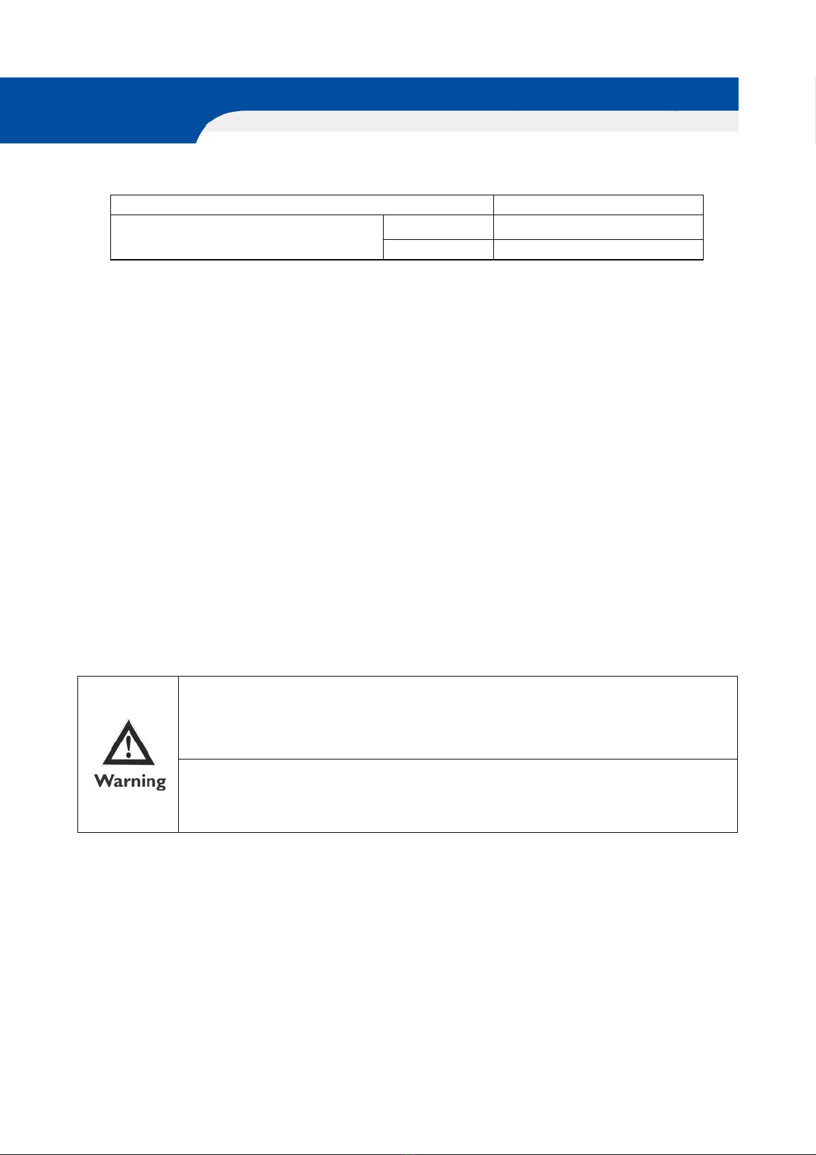
If any abnormity is found (like scorching smell), shut down the power, and contact our
service team, if it is still using in that case, the machine may be damaged and cause electric
shock or fire, maintenance can only be conducted by professional. The power should be
disconnected before touching the wiring device
The machine can be cleaned only when the power is disconnected, otherwise, it may cause
electric or injury. Don’t wash the machine with water, or it may cause electric shock, Stand
on a firm platform when cleaning ceiling air conditoner
8

Controller Introduction
Fresh Air Heat Pump is with intelligent touch screen controller to monitor indoor air quality (IAQ), in-
cluding index of indoor temperature, humidity, VOC concentration, CO2 concentration and PM2.5 value.
On/off button, to turn on or turn off the ventilator.
Mode switch, to switch heating mode, cooling mode, ventilation mode and auto mode.
Setting button, to set the parameters of the ventilator.
Timer on/off, after activate the timer on/off function, a “CLOCK” displayed on the top left corner.
When there is system error, there will be messages displayed on the top left corner.
Cooling mode, to set the cooling temperature and fan speed, then to confirm.
Heating mode, to set the heating temperature and fan speed, then to confirm.
Ventilation mode, to set the fan speed, then to confirm.
Auto mode, to set cooling and heating temperature, then to confirm.
1. Homepage
Setting button
Mode switch
On/off button
Timer on/off
2. Mode switch
9
Press Mode switch button to enter the modes setting as below

Controller Introduction
3. Setting button
Press setting button to enter basic setting, advanced setting, data query or maintenance setting.
Under basic setting page, press PM2.5 or CO2 value to set the targeted value, these 2 values will
influence the SA fan and EA fan speed after setting temperature achieved (compressor off).
A) Press basic setting to enter the basic setting page.
10

Controller Introduction
Press screen lock at the top right corner to enter the screen lock time setting.
Press time setting to enter the system time setting and timer on/off setting
a) press system time at the top right corner to set the system time
b) after setting the timer on and timer off time, then to click the “√“ to activate timer on/off
Press filter life to check the filters life, after cleaning or replacing the filters then can reset the life time.
11

B) Press advanced setting and enter the password 3333 to turn to advanced setting page. Through
advanced setting to set filter life, correction value and return difference value, also the defrost value.
Controller Introduction
Press filter life to set different filters life alarm
Press correction value & return difference to check and set the value
ADVANCED SETTING ONLY FOR ADMINISTRATOR, INCORRECT
SETTING MAY INFLUENCE THE VENTILATOR NORMAL WORK.
12

Controller Introduction
Press defrost setting to enter defrost duration time and defrosting interval time setting.
C) Press data query to enter the data checking, it is for administrator ONLY, if there is error displayed
on the homepage, then can enter this page to check the details, password is 5555, if the ventilator
works fine, then no need to enter this page.
D) Maintenance page, THIS PAGE IS FOR DEVELOPER OPTIONS, ANY NOT PROFESSIONALS ARE
NOT ALLOWED TO ENTER THIS PAGE, INCORRECT SETTING WILL RUIN THE VENTILATOR
SYSTEM, PLEASE CONTACT THE MANUFACTURE FOR THE PASSWORD IN CASE OF NECESSARY.
13

This manual suits for next models
1
Table of contents