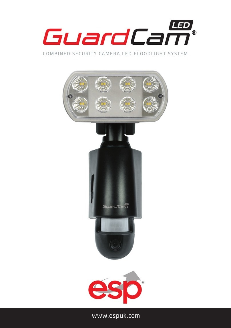
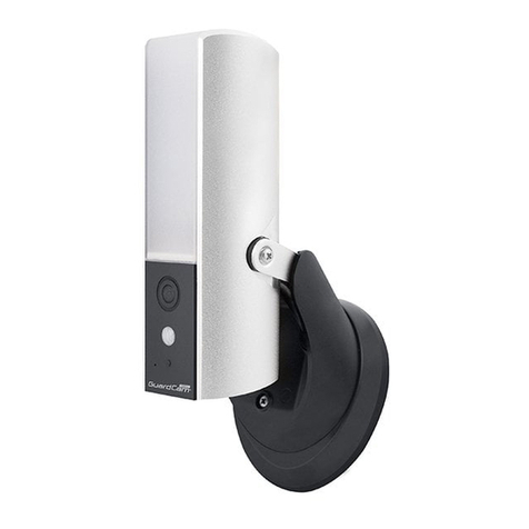
ESP GuardCamLED WIFI User manual

1
GUARDCAMLEDWIFI:COMBINED WI-FI SECURITY CAMERA LED FLOOD LIGHT SYSTEM
www.espuk.com
PRODUCT MANUAL

2
KIT CONTENT
TABLE OF CONTENTS
Kit Content . . . . . . . . . . . . . . . . . . . . . . . . . . . . . . . . . . . . . . . . . . . . . . . . . . . . . . . . . . . . . . . . . . . . . . . . . . . . 2
Product overview. . . . . . . . . . . . . . . .. . . . . . . . . . . . . . . . . . . . . . . . . . . . . . . . . . . . . . . . . . . . . . . . . . . . . . . . 3
Installing GuardCamLED WI-FI . . . . . . . . . . . . . . . . . . . . . . . . . . . . . . . . . . . . . . . . . . . . . . . . . . . . . . . . . . . 5
Insert/remove Micro SD Card . . . . . . . . . . . . . . . . . . . . . . . . . . . . . . . . . . . . . . . . . . . . . . . . . . . . . . . . . . . . 7
Adjusting the Settings . . . . . . . . . . . . . . . . . . . . . . . . . . . . . . . . . . . . . . . . . . . . . . . . . . . . . . . . . . . . . . . . . . 8
Network set-up . . . . . . . . . . . . . . . . . . . . . . . . . . . . . . . . . . . . . . . . . . . . . . . . . . . . . . . . . . . . . . . . . . . . . . . 10
App overview / lighting settings . . . . . . . . . . . . . . . . . . . . . . . . . . . . . . . . . . . . . . . . . . . . . . . . . . . . . . . . . 12
GuardCamLED WIFI
1 x Allen Key
2 x Screws
2 x Plastic Masonry Plugs
GuardCamLED WIFI
Micro SD Card
(speed class 10 required)
2
GUARDCAMDECO:COMBINED WI - F I S E CURI T Y CAMERA L ED F LOODL IGHT S Y S T EM
www.espuk.com
PRODUCT MANUAL

3
PRODUCT OVERVIEW
INSTALLATION TIPS
IMPORTANT
IF IN ANY DOUBT ABOUT THE INSTALLATION OF THIS PRODUCT, CONSULT A QUALIFIED
ELECTRICIAN
- This product must be grounded
- Do not mount the unit against inflammable surfaces
- The motion detector will not operate correctly if it is installed:
• Near the outlet of a central heating boiler
• Near air conditioning
• Pointing directly at moving vehicles
• Within sight of reflections from moving water
• Where other lamps could shine on the detector
BEFORE ATTEMPTING ANY INSTALLATION OR MAINTENANCE, ENSURE THAT THE ELECTRICAL
SUPPLY IS SWITCHED OFF AND THE CIRCUIT FUSES REMOVED OR THE CIRCUIT BREAKER IS IN
THE OFF POSITION.
Please make sure the voltage and polarity are correct before connection. Incorrect voltage may
cause electric shock.
FIG.1 FIG.2

4
Note: It is recommend to mount 2M above the ground for optimum performance, do not mount
the fixture below 1.2M. See below figure for details of performance range.
Detection range: 10M x 160°
4
Note: It is recommend to mount 2M above the ground for optimum performance, do not
mount the fixture below 1.2M. See below figure for details of performance range.
Detection range: 10M x 160°
GuardCam LED Manual.indd 4 11/01/2018 09:46:18
2m
4m 6m 8m 10m
2.5m

5
INSTALLING GUARDCAMLED WI-FI
It is strongly recommended APP & registration is complete prior to permanently fixing the
installation. After APP registration, where possible temporarily power the device to check a
strong Wi-Fi signal is being received at the intended installation site.
Wi-Fi devices rely on a strong and stable signal from the network. Performance and reliability
of Wi-Fi devices can become unpredictable if the signal strength is not sufficient for whatever
the reason.
If Wi-Fi signal is a possible issue, one solution is the numerous Wi-Fi signal enhancing devices
on the market to improve a network’s performance.
In addition, network connection for all devices (Wi-Fi or LAN) is limited by the bandwidth
allowance of the network, ensure that the bandwidth is suitable for the number of devices
which are being supported.
Please note; Guardcam requires 2.4GHZ Wi-Fi signal band.
1. Place plastic masonry plugs into desired surface aligning holes as shown below. Using an
electric screwdriver, fasten mounting plate directly to surface using screws.
2. Feed the cable through the back mounting box and bush the cable entry to avoid
abrasion to the cable.
3. Wire the unit as follows: (Ensure all wires are connected securely and that no loose strands
are exposed)
4. Make sure the polarity is correct. Double check the connections after wiring. Errors may damage
the motion sensor or cause a fire hazard.
5. Attach the unit to the mounting plate. You will first need to angle the unit back so that the
catch at the top of the mounting plate fits into slot on the back of the unit. Next lower the unit
until holes at the bottom of the mounting plate and unit are flush. Then screw into this hole,
tightening carefully.
6
Please allow 1 minute warm-up time after switching on
* Push the RESET button located on top of the housing after switching on.
Remove plastic lens cover from camera after installation.
Brown
Blue L
N
PDF !" "pdfFactory Pro" #$%&' www.pdffactory.com
Reset
Antenna
PDF !" "pdfFactory Pro" #$%&' www.pdffactory.com

7
INSERT/REMOVE MICRO SD CARD:
1. Unscrew the cover using provided Allen key , then insert the Micro SD card until it
automatically locks into place.
2. To remove Micro SD card, please push in SD card once to eject, then pull out

8
ADJUSTING THE SETTINGS:
Time Control
Turn the time control to”+” side to increase the illumination time (7 minutes max.), turn the control
to “-“ side to reduce the illumination time (5 seconds min.).
LUX Control
Adjust the ambient light at which the PIR
will activate the LED floodlight
Status LED
It takes 60 seconds from power up for the unit to
start normal operation. The red and blue LEDs will
flash twice when complete normal operation is ready.
Blue Status LED
Constant: Network connection
Slow Flash: APP live view under progress
Red Status LED
Double flash: Recording session
triggered Fast Flash: Defaulting / Reset
AC CABLE OUTLET
-Time+LUX
60
0 9 9
Status LED

9
Reset Button
Restores functions to default settings, press this button in case of system malfunction.
RESET
ANTENNA
PDF !" "pdfFactory Pro" #$%&' www.pdffactory.com

10
NETWORK SET-UP
Connect your smart phone to the Wi-Fi network that the Guardcam is to be added to. If the signal
strength of your Wi-Fi router is weak, reposition the devices until this improves.
There are two main stages for network setup;
1. Connect to the ‘Hotspot’ of the GuardcamLED Wi-Fi
2. Enter the network details into the APP to enable the GuardcamLED Wi-FI on the referred network.
If stage 2 is not completed, the unit will be unreachable outside of the hotspot.
1. GuardcamLED Wi -Fi Set-up
At this point the unit should be in the desired location and the Wi-Fi signal strengh confirmed.
If the signal strengh is unconfirmed it may be useful to temporaily power the unit using an
extention lead before final fixing.
Power should be applied, and the warm-up period of one minute has elapsed.
2. APP DOWNLOAD
Download and install the “ESP GuardcamDECO APP to your device.
3 HOTSPOT CONNECTION
(1) Go to the Wi-Fi setting on the mobile device.
Choose the Wi-Fi router with a prefix of HDxxxxxx.
Enter the default password (12345678) and save
the settings.
(2) Launch the APP, tap to add camera.
(3) Scan the QR code label on the bracket of the
camera to bring up the DID information
(XXXX-XXXXXX-XXXXXX), or manually type in the
DID, including the dashes.
(4) Name your camera (max. 20 characters).
(5) Enter the security code:123456 and select save.

11
4. Entering Wi-Fi Setting to Enable the Device on the network
(1) From the APP’s main screen enter the settings menu , additional settings and then the
advanced menu. Inside the advanced menu is a Wi-Fi settings page. Please enter the
details of the preferred network.
(2) The camera will be off-line for around 60 seconds to reboot for the connection to establish.
When the camera connects to Wi-Fi router successfully, the Blue LED will be constant.
(3) Insure the smart phone has reconnected to the correct network and test the functionality
of the unit.
APP Connection
Viewing from a mobile phone relies on a strong Wi-Fi signal or ensure a strong 3G or 4G
signal is available. For IOS it is recommended that the APP is left running in the background
in order to benefit from the best performance. For Android, the APP must be left running in
the background to receive any service from the product.
ESP are unable to guarantee that every device will be compatible with any ESP product
and software supplied.
Specific models of phone, tablet or other device, the hardware it contains, the service
provider, the types of data services offered and specific phone / device plan will all affect
the performance of PC / mobile device for remote viewing.
Note:
If you do not see your Wi-Fi router in the WI-FI SETTING section, please enable your router's SSID
broadcasting function, which usually is the name of your HOME WI-FI NETWORK. Most of the Wi-Fi
routers broadcast the Service Set Identifier (SSID) by default.
The unit can only accept SSID composed with English alphabet characters.
Non-English characters (! @#$%^&*) cannot be accepted.
ADVANCED Enter Admin Password
(default 123456)

12
APP OVERVIEW / LIGHTING SETTINGS
LED Lamp ON/OFF
FOLLOW THE STEPS BELOW FOR EVENT PLAYBACK
1. Tap and then the
2. Select the time interval from the event list.
3. Tap to select the event for playback.
4. If you want to store the files in mobile device, tap to download.
(Best while under Wi-Fi environment due to larger high definition data size).

13
SCAN QR CODE FOR FULL GUARDCAMLED WI-FI MANUAL
WHICH INCLUDES ADVANCED APP MENU

Elite Security Products
Unit 7, Target Park, Shawbank Rd
Lakeside, Redditch B98 8YN
Telephone: 01527 51 51 50
Fax: 01527 51 51 43
email: [email protected]
E&OE - Errors and omissions excepted. A19
www.espuk.com
Table of contents
Other ESP Security Camera manuals

ESP
ESP REKIPC36FBW User manual

ESP
ESP HDVC36FD User manual

ESP
ESP REKHDC36FBG User manual

ESP
ESP GuardCam RF User manual

ESP
ESP REKIPC36FDW User manual

ESP
ESP FHDVC18PTZ User manual

ESP
ESP Recor HD REKHDC36FBG18P User manual

ESP
ESP HDVC36FDW User manual

ESP
ESP IRCAM1000 Quick start guide

ESP
ESP GuardCam LED User manual

ESP
ESP GuardCamDeco User manual

ESP
ESP DomeVF Pro User manual

ESP
ESP PTZ10EXT User manual

ESP
ESP GuardCamDeco User manual

ESP
ESP Fort ECSPCAM User manual

ESP
ESP GuardCam LED User manual

ESP
ESP DECO GuardCam User manual

ESP
ESP IRCAM900 Pro User manual

ESP
ESP GuardCam LED User manual

ESP
ESP SHDVC622VFBW User manual