ESPRIT X6 User manual

PLEASE CAREFULLY READ THIS ENTIRE MANUAL BEFORE
OPERATING YOUR ELLIPTICAL!
OWNER’S MANUAL
Esprit X6 Cross Trainer
-ESP0034-

1
WARNING
-
Read all instructions before using this appliance.
■
Do not operate elliptical on deeply padded, plush or shag carpet. Damage
to both carpet and elliptical may result.
■
Keep children away from the elliptical. There are obvious pinch points and
other caution areas that can cause harm.
■
Keep hands away from all moving parts.
■
Never operate the elliptical if it has a damaged cord or plug. If the elliptical
is not working properly, call your dealer.
■
Keep the cord away from heated surfaces.
■
Do not operate where aerosol spray products are being used or where
oxygen is being administered. Sparks from the motor may ignite a highly
gaseous environment.
■
Never drop or insert any object into any openings.
■
Do not use outdoors.
■
To disconnect, turn all controls to the off position, then remove the plug
from the outlet.
■
Do not attempt to use your elliptical for any purpose other than for the
purpose it is intended.
■
The pulse sensors are not medical devices. Various factors, including the
user’s movement, may affect the accuracy of heart rate readings. The
pulse sensors are intended only as exercise aids in determining heart rate
trends in general.
■
Wear proper shoes. High heels, dress shoes, sandals or bare feet are not
suitable for use on your elliptical. Quality athletic shoes are recommended
to avoid leg fatigue.
SAVE THESE INSTRUCTIONS - THINK SAFETY!
CAUTION!! Please be careful when un-packing the carton.
ESP0034/ X6_ver. B
Safety Hints
2
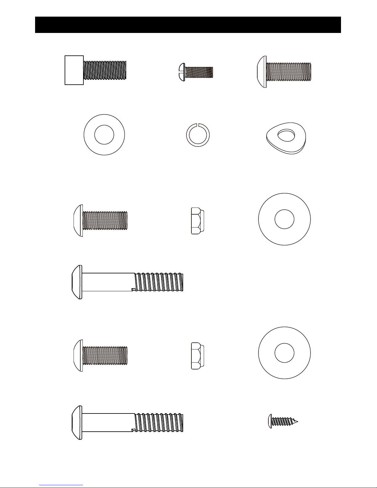
Assembly Pack Check List
STEP
2
.
STEP
3
.
STEP 1.
#44- 5/16” Flat
Washer (8pcs)
#45- 5/16" Curved
Washer (1pc)
#102- 5/16" × 3/4" Socket
Head Cap Bolt (9 pcs)
#53- M5 × 12 mm Phillips
Head Screw (4pcs)
#46- 5/16" ×1.5T
Split Washer (9pcs)
#43- 5/16" × 3/4" Button
Head Socket Bolt (1pc)
#100- 8.5x23x1.5T
Flat Washer (1pc)
#55- 5/16" Nyloc
Nut (2pcs)
#56- 5/16" ×1-3/4" Button
Head Socket Bolt (2pcs)
#43- 5/16" × 3/4" Button
Head Socket Bolt (1pc)
#55- 5/16" Nyloc
Nut (2pcs)
#56- 5/16" ×1-3/4" Button
Head Socket Bolt (2pcs)
#52- 5 × 12mm Sheet
Metal Screw (4pcs)
#100- 8.5x23x1.5T
Flat Washer (1pc)
#43- 5/16" × 3/4" Button
Head Socket Bolt (4pcs)

3
Assembly Pack Check List
STEP
4
.
#68- Combination M5 Allen Wrench &
Phillips Head Screw Driver (2pcs)
#69- 19m/m Wrench (1pc)
# 98- 5/16" × 1"
Button Head Socket Bolt
(2pcs)
#44- 5/16” Flat
Washer (2pcs)
#30- 1/2" Nyloc
Nut (2pcs)
#29- 1/2" × 70mm
Carriage Bolt (2pcs)
#52- 5 × 12mm
Sheet Metal Screw
(2pcs)
#46- 5/16" Split
Washer (2pcs)
#103- 6 mm Allen Wrench (1pcs)

4
STEP 1:
1. Locate the Console Mast (9) and slide on Console Mast Cover (82) Make sure the
cover is facing the correct direction, as shown below, before sliding onto mast. Install
the wiring harness (94) into the bottom of the mast and out the top. Be careful when
installing the console mast to the mainframe so as not to pinch or cut the wiring
harness; damage to the console may occur.
2.
Install the console mast on the mainframe using the 6mm Allen Wrench (103) to
tighten 5pcs of 5/16” Socket Head Cap Bolts (102) , 4pcs of 5/16” Flat Washers (44) ,
5pcs of 5/16" Split Washers (46) and 1pcs of 5/16" Curved Washer (45).
Snap the
Console Mast Cover (82) in place on the body of the bike.
3. Route the hand pulse wires (96) from the stationary handle bars (10, 11) through
Console Mast (9) as shown below. Use M5 Allen Wrench (68) to tighten 4pcs of 5/16”
Button Head Socket Bolts (43) to secure both handles on the Console Mast (9).
4. Connect the cables (94 & 96) to the Console (58) and install console onto the Mast (9)
with 4pcs of M5 × 12L Phillips head screws (53) by using the Phillips Head Screw
Driver (68).
5. Secure Front Stabilizer (12) and Rear Stabilizer (13) with 4pcs of 5/16” Socket Head
Cap Bolts (102), 4pcs of 5/16" Split Washers (46) and 4pcs of 5/16” Flat Washers (44)
by using 6mm Allen Wrench (103).
Assembly Instructions

5

6
STEP 2:
1. Locate the Right Swing Arm (Upper) (8) and install it through the Swing Arm Bushing
(23) and secure to the Lower swing arm (6). Use M5 Allen Wrench (68) to tighten 2pcs
of 5/16” Button Head Socket Bolts (56) and 2pcs of 5/16" Nyloc Nuts (55) to the swing
arm assembly.
2. Locate the Swing Arm Axle (22) and slide it through the console mast bushings, then
through the Handle Bar Cover (78) and Lower swing arm (6). Use the M5 Allen Wrench
(68) to tighten the 5/16” Button Head Socket Bolt (43) and 8.5mm x 23 Flat Washer
(100) to secure to the Swing Arm Axle (22).
7
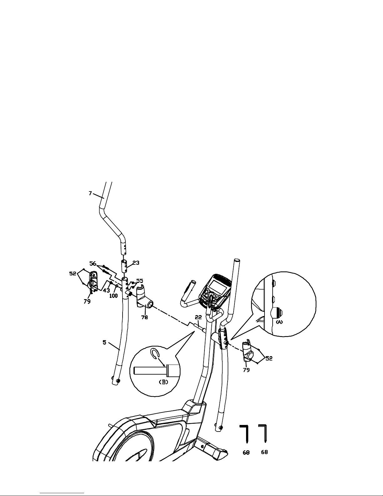
STEP 3:
1. Locate the Left Swing Arm (Upper) (7) and install it through the Swing Arm Bushing
(23) and secure to the Lower swing arm (5). Use M5 Allen Wrench (68) to tighten 2pcs
of 5/16” Button Head Socket Bolts (56) and 2pcs of 5/16" Nyloc Nuts (55) to the swing
arm assembly.
2. Locate the Inner Handle Bar Cover (78) and install on the Lower swing arm and slide
the swing arm with cover onto the axle (22). Secure the swing arm to the axle using
the M5 Allen Wrench (68) to tighten the 5/16” Button Head Socket Bolt (43) and
8.5mm x23 Flat Washer (100) on the Swing Arm Axle (22).
3. If there is seam at area A, please install C-ring at area B. Use Combination M5 Allen
Wrench & Phillips Head Screw Driver (68) to unscrew and release 5/16" × 3/4" Button
Head Socket Bolt (43) and 8.5 × 23 × 1.5T Flat Washer(100) and take apart left Lower
Handle Bar (5) together with Handle Bar Cover-A (78) to install plastic C-ring at area B,
then follow step 2 to install Handle Bar Cover-A(78) and left Lower Handle Bar (5).
Finally, install two Handle Bar Covers-B (79) and use Combination M5 Allen Wrench &
Phillips Head Screw Driver (68) to tighten 5 × 12mm Sheet Metal Screws (52).
8
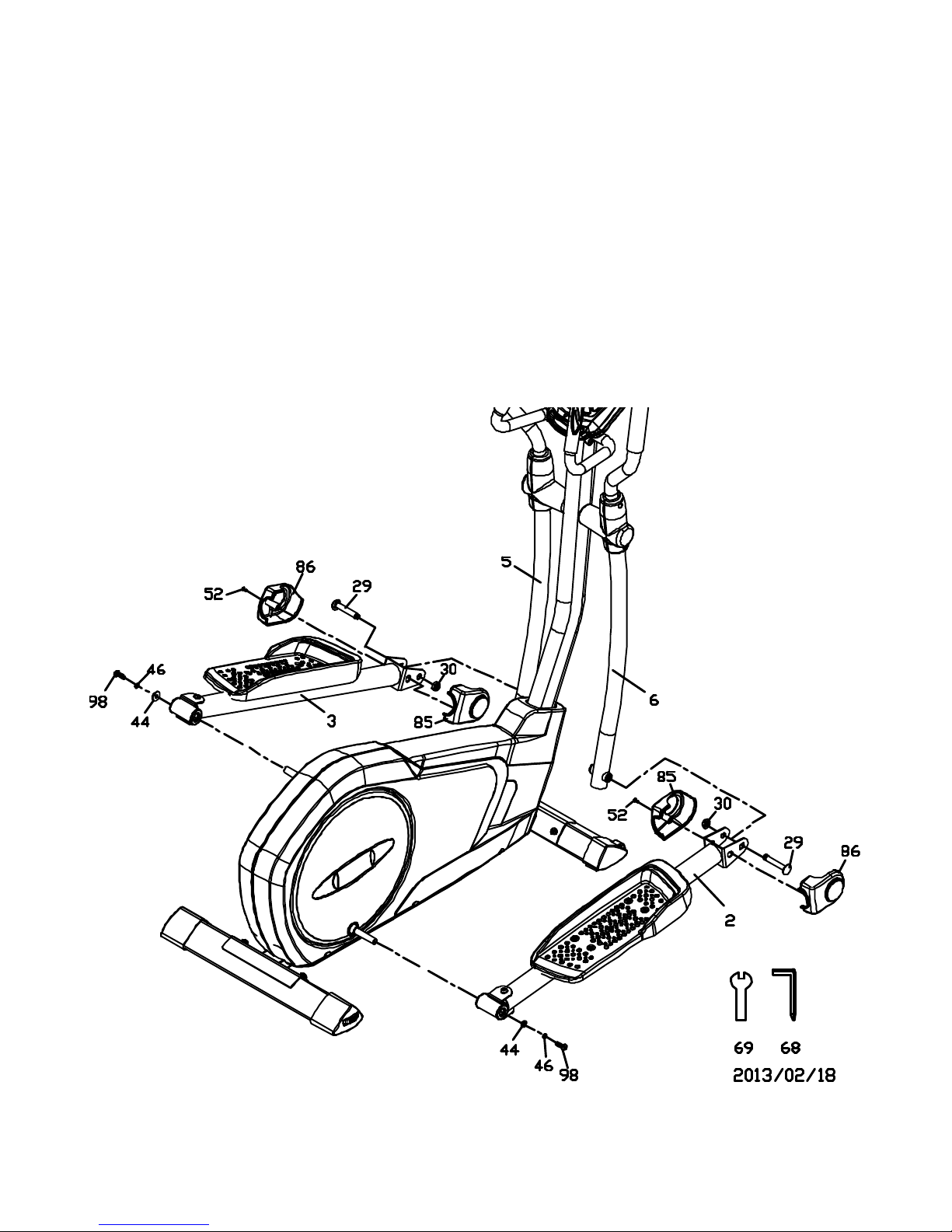
STEP 4:
1. Locate Right side Pedal Arm Assembly (2) and install onto the pedal axle at the
large rotating wheel at the rear of the elliptical. Use the M5 Allen Wrench (68) to
tighten the 5/16” Button Head Socket Bolt (98), 5/16" Split Washer (46) and 5/16”
Flat Washer (44).
2. Locate the 1/2" × 70mm Carriage Bolt (29) and slide through the bracket at the front
of the Pedal Arm Assembly (2) and Lower swing arm (6). Use the19m/m Wrench (69)
to tighten the 1/2" Nyloc Nut (30) to the carriage bolt (29).
3. Install Pedal Arm Covers (85, 86) on the Pedal Arm Assembly (2) and use Phillips
Head Screw Driver (68) to tighten the 5 × 12mm Sheet Metal Screw (52).
4. Repeat steps 1-3 above for the left side pedal arm assembly.
9
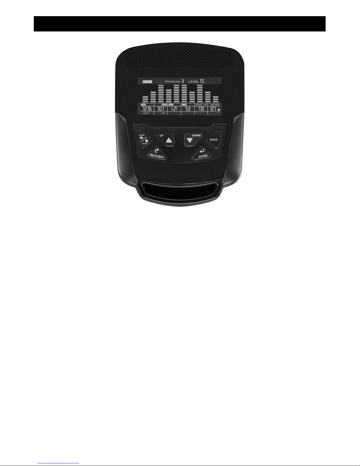
Key Functions
START/STOP: 1. Starts & Pauses workouts.
2. Starts body fat measurement.
3. Holding key for 3 seconds will reset all functions and values to zero.
DOWN: Decreases value of selected workout parameter: TIME, DISTANCE, etc. During the
workout it will decrease the resistance load.
UP: Increases value of selected workout parameter. During the workout it will increase the
resistance load.
ENTER: To input desired value or work out mode.
RECOVERY: Press to enter into heart rate Recovery function. Only works when the computer is
receiving a heart rate value. Recovery is an indication of Fitness Level. It is a one minute
measurement taken immediately after and exercise session and provides a score from1 to 6.
A score of 1 is an indication of a high level of fitness and a score of 6 indicates poor condition.
MODE: Press to switch display from RPM to SPEED, ODO to DIST, WATT to CALORIES.
Workout Selection
After power-up, use the UP or DOWN keys to select a workout program then pressing ENTER.
There are 7 basic workout programs: Manual, Pre- programs, Watt Program, Body Fat
Program, Target Heart Rate program, Heart Rate Control program and User Program.
Console

10
Functions:
1. SPEED: Displays current training speed. Maximum speed is 99.9 KM/H or MILE/H.
2. RPM: Displays current pedal rotations per minute.
3. TIME: Accumulates workout time from 00:00 to 99:59. Or users can preset the target time
desired.
4. DIST: Accumulates the workout distance form 0.00 up to 999.9 KM or Mile. Or users can
preset the target distance they want to reach.
5. ODO: Displays the total accumulated distance from 0.0 to 999.9KM or Mile.
6. CAL: Accumulates the calories burned from 0 to 9999. Or users can preset the target
Calories they want to burn.
7. WATT: Displays current watt.
8. HEART RATE: Displays the current heart rate in beats per minute.
9. TARGET H. R.: Users can preset their Target Heart Rate.
10. PROGRAM: There are 24 different programs to choose from for training.
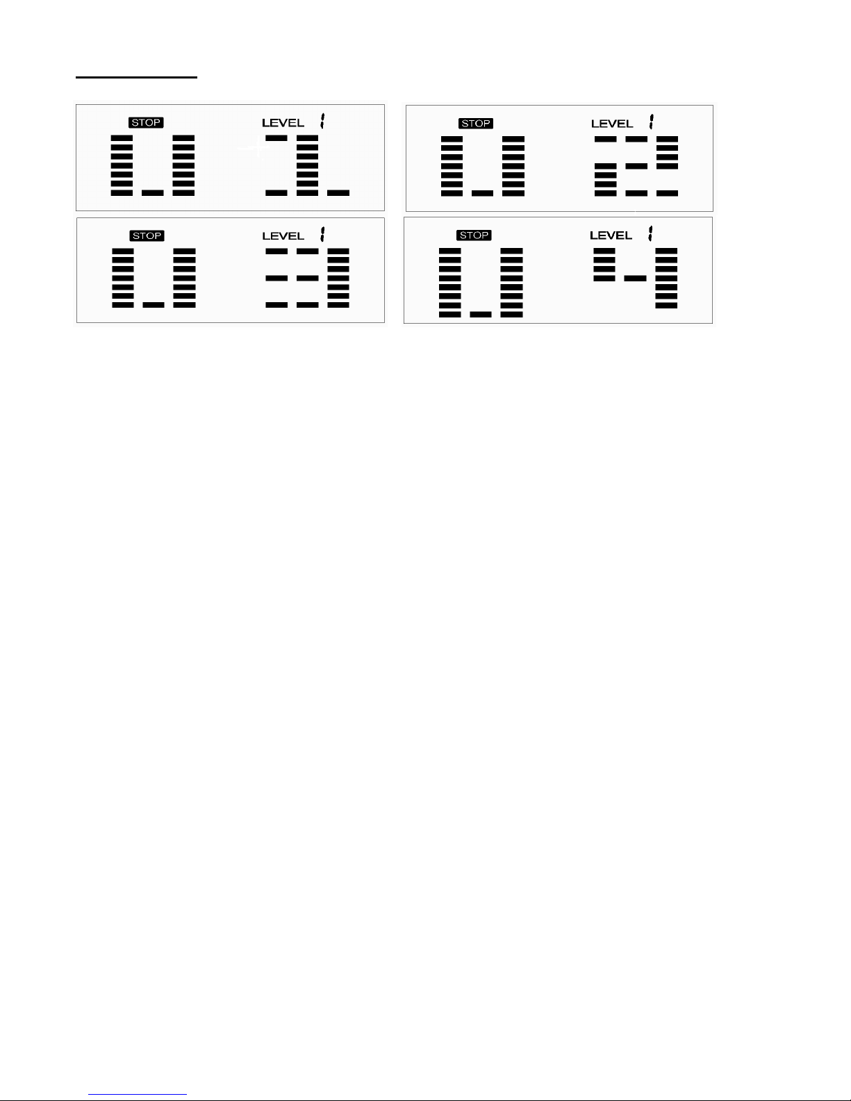
11. LEVEL: The programs have 24 levels of work displayed in 8 bars in each column. Each
column represents 1 minute workout (Unless time is changed to a new value for count down)
and each bar represents 3 levels of work.
12. Music: There is an audio-input port on the top of the monitor. Users can connect an MP3,
smart phone or other audio source to the port.
Workout Parameters:
TIME / DISTANCE / CALORIES / AGE / WATT / TARGET HEART RATE
Setting Workout Parameters:
After selecting desired workout program (Manual, Pre-set Programs, Watt Program, Target
Heart Rate, Heart Rate Control and User Program) you may pre-set several workout parameters
for desired results.
Note: Some parameters are not adjustable in certain programs. Time and Distance can
not be set up in the same workout.
Once a program has been selected pressing ENTER will make “Time” parameter flash.
Using UP OR DOWN KEY you may set the desired time value. Press ENTER KEY to input
value.
Flashing prompt will move to the next parameter. Continue use of UP OR DOWN KEY. Press
START/STOP to start workout.

11
More About Workout Parameters
Parameter
Setting
Range
Default
Value
Increment/
Decrement
Description
Time
0:00~ 99:00
00:00 ± 1:00
1. When display is 0:00, Time will count
up.
2. When time is 1:00-99:00,
It will count down to 0.
Distance
0.00~999.0
0.00
±1.0
1.When display is 0.0,
Distance will count up.
2.When Distance is 1.0~999.0, it will
count down to 0.
Calories
0~9995 0.0 ±5
1.When display is 0, Calories will count
up.
2.When Calories is 5~9995,
it will count down to 0.
Watt 40~250 100 ±5
User can set watt value only in Watt
control program.
Age 10~99 30 ±1
Target HR will be based on Age. When
Heart Rate exceeds Target H.R, the
number of Heart Rate will flash.
Pulse 60~220 90 ±1 Setting Parameters for Target heart
rate.
Program Operation
Manual
(
((
(
P1
)
))
)
Program profile
Select “Manual ” using UP OR DOWN KEY then press ENTER KEY. 1
St
parameter, “Time”
will flash so value can be adjusted using UP OR DOWN KEY .Press ENTER KEY to save
value & move to next parameter to be adjusted.
**(If user sets up the target time to workout then the next parameter of Distance can
not be adjusted) Continue through all desired parameters, pressing START/STOP to start
workout.
Note: When any One of the workout parameters counts down to zero the console emits a
beep sound and the workout stops automatically. Press START KEY to continue the
workout to reach the unfinished workout goals set.

12
Pre-programs (P2~P13)
Program profile
ROLLING VALLEY
FAT BURN RAMP
STEPS OBSTACLE
INTERVALS PLATEAU
CLIMBING OFF ROAD
HILL
FASTREK

13
There are 12 pre-set program profiles ready for use
:
::
:
ROLLING, VALLEY, FAT BURN,
RAMP, STEPS, OBSTACLE, INTERVALS, PLATEAU, CLIMBING, OFF ROAD, HILL,
FASTREK. All program profiles have 24 levels of resistance.
Setting Parameters for Pre-set programs
Select one of pre-set programs using UP OR DOWN KEY then pressing ENTER KEY.
The 1
St
parameter, “Time” will flash indicating the value can be adjusted using UP OR
DOWN KEY .Press ENTER KEY to save value & move to next parameter to be adjusted.
Continue through all desired parameters, pressing START/STOP to start workout.
Workout in any pre-program
Users can exercise at different levels of intensity in different intervals as the profiles flash.
Users may adjust the resistance level using the UP/DOWN keys during the workout.
Note: If user sets up the target time to workout then the next parameter of Distance can not
be adjusted.
When any One of the workout parameters counts down to zero the
console emits a beep sound and the workout stops automatically. Press START
KEY to continue the workout to reach the unfinished workout goals set.
Watt control program(P14)
Program profile
Setting Parameters for Watt control program
Select “Watt control program” using UP OR DOWN KEY then press ENTER KEY.
The 1
St
parameter, “Time” will flash indicating the value can be adjusted using UP OR
DOWN KEY .Press ENTER KEY to save value & move to next parameter to be
adjusted.
**(If user sets up the target time to workout, then the next parameter of Distance
can not be adjusted) Continue through all desired parameters, pressing
START/STOP to start workout.
Note:
When any One of the workout parameters counts down to zero the console
emits a beep sound and the workout stops automatically. Press START KEY
to continue the workout to reach the unfinished workout goals set.
Computer will adjust the resistance load automatically depending on the
speed to maintain a constant watt value. User can use up down key to
adjust the watt value during workout.

14
BODY FAT MEASUREMENT
Setting Data for Body Fat
Select “BODY FAT” using UP OR DOWN KEY then pressing ENTER.
“Male” will flash indicating the Gender can be adjusted using UP OR DOWN KEY. Press
ENTER to save gender setting & move to next setting.
A Height of “175” will flash indicating the Height can be adjusted using UP OR DOWN KEY.
Press ENTER KEY to save value & move to next setting.
A Weight of “75” will flash indicating the Weight can be adjusted using the UP OR DOWN
KEY. Press ENTER KEY to save vale & move to next setting.
An Age of “30” will flash indicating the Age can be adjusted using UP OR DOWN KEY.
Press ENTER to save value.
Press START/STOP to start measurement. Please be sure to grasp the hand pulse grips.
After 15 seconds the display will show Body Fat %, BMR, BMI & BODY TYPE.
NOTE: Body Types:
There are 9 possible body types according to the FAT% calculated. Type 1 is from
5% to 9%. Type 2 is from 10% to 14%. Type 3 is from 15% to 19%. Type 4 is from
20% to 24%. Type 5 is from 25% to 29%. Type 6 is from 30% to 34%. Type 7 is
from 35% to 39%. Type 8 is from 40% to 44%. Type 9 is from 45% to 50%.
BMR: Basal Metabolic Rate is the amount of daily energy expended at rest.
BMI: Body Mass Index is a general body type based on height and weight.
Press START/STOP KEY to return the main Display.
TARGET HEART RATE Program
Program profile
Setting Parameters for TARGET H.R
Select “TARGET H.R.” using UP OR DOWN KEY then press ENTER KEY. The 1
St
parameter, “Time” will flash indicating the value can be adjusted using UP OR DOWN KEY.
Press ENTER KEY to save value & move to next parameter to be adjusted.
**(If user sets up the target time to workout, then the next parameter of Distance can
not be adjusted) Continue through all desired parameters, pressing START/STOP to start
workout.
15
Note: If your Pulse measurement is above or below (± 5) the TARGET H.R setting, the
computer will adjust the resistance load automatically; it will check approximately
every 10 seconds. If the heart rate signal disappears, the computer will keep the
resistance load constant for 60 seconds then it will decrease the resistance load 1
level every 10s.
When any One of the workout parameters counts down to zero the console
emits a beep sound and the workout stops automatically. Press START KEY to
continue the workout to reach the unfinished workout goals set.
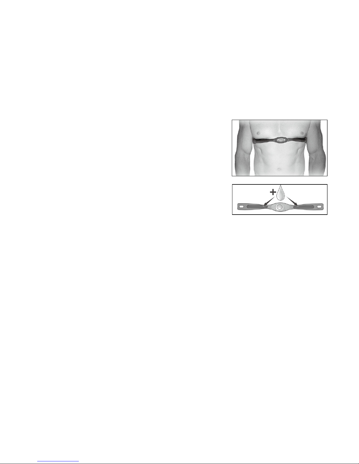
Wearing The Chest Strap
(Sold Separately)
1. Attach the transmitter to the elastic strap using the locking
parts.
2. Adjust the strap as tightly as possible as long as the strap
is not too tight to remain comfortable.
3. Position the transmitter with the logo centered in the
middle of your torso facing away from your chest (some
people must position the transmitter slightly left of center).
Attach the final end of the elastic strap by inserting the
round end and, using the locking parts, secure the
transmitter and strap around your chest.
4. Position the transmitter directly below the pectoral
muscles.
5. Sweat is the best conductor to measure very minute heart beat electrical signals.
However, plain water can also be used to pre-wet the electrodes (2 ribbed oval areas on the
reverse side of the belt and both sides of the transmitter). It’s also recommended that you
wear the transmitter strap a few minutes before your work out. Some users, because of
body chemistry, have a more difficult time in achieving a strong, steady signal at the
beginning. After “warming up”, this problem lessens. As noted, wearing clothing over the
transmitter/strap doesn’t affect performance.
6. Your workout must be within range - distance between transmitter/receiver – to achieve a
strong steady signal. The length of range may vary somewhat but generally stay close
enough to the console to maintain good, strong, reliable readings. Wearing the transmitter
directly on bare skin assures you of proper operation. If you wish, you may wear the
transmitter over a shirt. To do so, wet the areas of the shirt that the electrodes will rest upon.

16
HEART RATE CONTROL Program
Program profile
There are 4 selection for target pulse:
HRC- 55% TARGET H.R= 55% of (220-AGE)
HRC - 65% TARGET H.R= 65% of (220-AGE)
HRC - 75% TARGET H.R= 75% of (220-AGE)
HRC - 85% TARGET H.R= 85% of (220-AGE)
Setting Parameters for HEART RATE CONTROL
Select one of the “Heart Rate Control Program” using UP OR DOWN KEY then press
ENTER KEY. The 1
St
parameter “Time” will flash indicating the value can be adjusted using
UP OR DOWN KEY. Press ENTER KEY to save value & move to next parameter to be
adjusted.
**(If user sets up the target time to workout, then the next parameter of Distance can
not be adjusted) Continue through all desired parameters, pressing START/STOP to start
workout.
Note:
If your Pulse measurement is above or below (± 5) the TARGET H.R setting, the
computer will adjust the resistance load automatically; it will check approximately
every 10 seconds. If the heart rate signal disappears, the computer will keep the
resistance load constant for 60 seconds then it will decrease the resistance load 1
level every 10s.
When any One of the workout parameters counts down to zero the console
emits a beep sound and the workout stops automatically. Press START KEY to
continue the workout to reach the unfinished workout goals set.
17
User Program
Program profile
4 User programs allow the user to create their own personal program.
Setting Parameters for User Program
Select “User” using UP OR DOWN KEY then press ENTER KEY. The 1
St
parameter, “Time”
will flash indicating the value can be adjusted using UP OR DOWN KEY. Press ENTER
KEY to save value & move to next parameter to be adjusted.
**(If user sets up the target time to workout, then the next parameter of Distance can
not be adjusted) Continue through all desired parameters .
After completing parameter set up, row 1 of the profile will be flashing. Use UP OR DOWN
KEY to adjust level then press ENTER until finished (10 times total). Press START/STOP to
start workout.
Note:
When any One of the workout parameters counts down to zero the console
emits a beep sound and the workout stops automatically. Press START KEY
to continue the workout to reach the unfinished workout goals set.

18
NO.
DESCRIPTION
O'TY
1
Main Frame
1
2
Pedal Bar Assembly (R)
1
3
Pedal Bar Assembly (L)
1
4
Cross Bar
2
5
Lower Handle Bar (L)
1
6
Lower Handle Bar (R)
1
7
Left Swing Arm (Upper)
1
8
Right Swing Arm (Upper)
1
9
Console Mast
1
10
Hand Pulse Sensor Arm (L)
1
11
Hand Pulse Sensor Arm (R)
1
12
Front Stabilizer
1
13
Rear Stabilizer
1
14
Crank Axle
1
15
Pedal Axle Bushing Assembly
2
16
Flywheel
1
17
Flywheel Magnets Mounting Plate
1
19
Drive Pulley
1
20
Idl
er Bracket
1
21
Idler Wheel
1
22
Swing Arm Axle
1
23
Swing Arm Bushing
2
24
Ø38.1 × 34.1 × 16 × 21L_Bushing
4
25
Pedal Axle Spacer
2
26
15.9 × 22.2m/m_Podwer metallurgy Bushing
6
27
12.7 × 18m/m_Podwer metallurgy Bushing
4
28
6004_Flywheel Bearing
2
29
1/2" × 70L_Carriage Bolt
2
30
1/2" × 8T_Nyloc Nut
2
31
Belt
1
32
M8 × 170L_J Bolt
1
33
M8 × 7T_Nyloc Nut
1
35
3/8" × 27L_Carriage Bolt
1
36
3/8" × 7T_Nyloc Nut
1
Parts List

19
NO.
DESCRIPTION
O'TY
37
Sleeve
1
38
5/16" × 20L_Carriage Bolt
1
39
20m/m_C R
ing
2
40
M10 × 1.25_Nut
2
41
3/8"
-
26UNF × 4T_Nut
2
42
3/8"
-
26UNF × 7T_Nut
2
43
5/16" × 3/4"_Button Head Socket Bolt
6
44
5/16" × 18 × 1.5T_Flat Washer
14
45
5/16" × 19 × 1.5T_Curved Washer
1
46
5/16" × 1.5T_Split Washer
11
47
1/4" × 5/8"_Hex Head B
olt
4
48
1/4" × 5.5T_Nyloc Nut
4
49
1/4" × 13 × 1T_Flat Washer
4
50
1/4"_Split Washer
4
51
5 × 16L_Tapping Screw
6
52
5 × 12L_Sheet Metal Screw
6
53
M5 × 12L_Phillips Head Screw
5
54
M5 × 30L_Phillips Head Screw
8
55
5/16" × 6T_Nyloc Nut
8
56
5/16
" × 1
-
3/4"_Button Head Socket Bolt
4
57
5/16" × 2
-
1/2"_Button Head Socket Bolt
3
58
Console
1
59
Gear Motor
1
60
Magnet
1
61
Handpulse Sensor (w/o wire)
2
62
200m/m_Sensor W/Cable
1
63
Steel Cable
1
64
Ø31.8 × 3T × 400L_Handgrip Foam
2
65
Ø32
-
3T_B
utton Head Plug
2
66
Ø25.4 × 3T × 150L_Handgrip Foam
2
67
Ø25.4
-
3T_Button Head Plug
2
68
Combination M5 Allen Wrench & Phillips Head Screw Driver
2
69
19m/m_Wrench
1
70
Left Stabilizer End Cap (Front)
1
71
Right Stabilizer End Cap (Rear)
1
72
Left S
tabilizer End Cap (Front)
1
73
Right Stabilizer End Cap (Rear)
1
Table of contents
Other ESPRIT Fitness Equipment manuals

Popular Fitness Equipment manuals by other brands


G-FITNESS
G-FITNESS AIR ROWER user manual

CAPITAL SPORTS
CAPITAL SPORTS Dominate Edition 10028796 manual

Martin System
Martin System TT4FK user guide

CIRCLE FITNESS
CIRCLE FITNESS E7 owner's manual

G-FITNESS
G-FITNESS TZ-6017 user manual

Accelerated Care Plus
Accelerated Care Plus OMNISTIM FX2 CYCLE/WALK user manual


