Essen BioScience IncuCyte ZOOM User manual

Page 1
IncuCyte™ ZOOM Users Manual
2013A
Essen BioScience, Inc.
www.EssenBioScience.com

Page 2
Table of Contents
IncuCyte™ ZOOM Users Manual....................................................................................................................1
2013A ..............................................................................................................................................................1
Chapter 1: Warranty .................................................................................................................................5
1.1 Limitation of Warranty....................................................................................................................5
1.2 Exclusive Remedies .........................................................................................................................5
1.3 Warnings and Disclaimers...............................................................................................................5
Chapter 2: Getting to know your IncuCyte™ ZOOM.......................................................................................6
2.1 Intended Use...................................................................................................................................6
2.2 IncuCyte™ ZOOM Configurations ...................................................................................................6
2.3 Safety has Priority ...........................................................................................................................6
2.4 IncuCyte™ZOOM Specifications.....................................................................................................7
2.5 Unpacking and Checking the IncuCyte™.........................................................................................8
Chapter 3: Installation of the IncuCyte™ZOOM Hardware..........................................................................10
3.1 IncuCyte™ZOOM Hardware Features ..........................................................................................10
3.2 Removing the Shipping Pin ...........................................................................................................12
3.3 Installing the Filter Module...........................................................................................................13
3.4 Installing an Objective...................................................................................................................14
3.5 Positioning the Controller.............................................................................................................14
3.6 Placing the Microscope into the Incubator...................................................................................15
3.7 Switching the IncuCyte™ZOOM On and Off.................................................................................16
3.8 Warming up the Microscope ........................................................................................................16
3.8.1 Auto Warm-up ......................................................................................................................17
3.8.2 IncuCyte™ Controller Air Filter..............................................................................................17
Chapter 4: Establishing Network Connections .......................................................................................18
4.1 DHCP Based Networks ..................................................................................................................18
4.1.1 Verifying the IncuCyte™ Controller Network Connection: Windows Vista or Windows 7...19
4.1.2 Verifying the IncuCyte™ Controller Network Connection: Windows XP ..............................19
4.2 Static IP Based Networks ..............................................................................................................20
Chapter 5: Installation of the IncuCyte™ Control Software....................................................................20

Page 3
5.1 IncuCyte™ Control Software Installation using Windows XP........................................................20
5.2 IncuCyte™ Control Software Installation using Windows Vista and Windows 7..........................21
5.3 Connecting ....................................................................................................................................21
5.3.1 Setting the Date and Time ....................................................................................................21
5.3.2 Establishing User Accounts ...................................................................................................22
5.4 Remote Administration of the Controller.....................................................................................23
Chapter 6: Calibrating the IncuCyte™ZOOM System.............................................................................24
6.1 System Calibration ........................................................................................................................24
6.2 Fluorescence Calibration...............................................................................................................26
6.2.1 FLR Calibration Results..........................................................................................................27
Chapter 7: Cell Culture Monitoring and Data Analysis ...........................................................................27
7.1 Introduction ..................................................................................................................................27
7.2 User Interface ...............................................................................................................................28
7.3 Scheduling Scans and Loading Vessels..........................................................................................29
7.3.1 24-Hour Repeating................................................................................................................29
7.3.2 Scan on Demand ...................................................................................................................34
7.4 Finding and Viewing Scanned Vessels...........................................................................................35
7.4.1 Finding Scanned Vessels .......................................................................................................35
7.4.2 Vessel View ...........................................................................................................................37
7.5 Data Processing.............................................................................................................................40
7.5.1 Assay Mode vs. Established Mode........................................................................................40
7.5.2 Analysis Job Utilities..............................................................................................................41
7.6 Graphing and Exporting Data........................................................................................................47
7.6.1 Create a Graph ......................................................................................................................47
7.6.2 Microplate Graphing .............................................................................................................61
7.6.3 Exporting Experimental Data ................................................................................................62
7.6.4 Saving and Printing Graphs ...................................................................................................66
7.7 Exporting Images and Movies.......................................................................................................66
7.7.1 Exporting Images Overview ..................................................................................................66
7.7.2 Exporting Movies Overview ..................................................................................................72

Page 4
7.8 Archiving .......................................................................................................................................74
7.8.1 Archiving Vessels...................................................................................................................75
7.8.2 Opening an Archive...............................................................................................................76
7.9 Hardware ......................................................................................................................................77
7.9.1 Selecting and Placing Trays ...................................................................................................77
7.9.2 Changing Objectives..............................................................................................................79
7.10 Plate Map Editor ...........................................................................................................................81
7.10.1 Selecting Wells ......................................................................................................................82
7.10.2 Adding Well Items.................................................................................................................82
Chapter 8: Special Modules and Scan Types ..........................................................................................85
8.1 Scan Types available with Essen ImageLock™ ..............................................................................85
8.1.1 Standard (with Lock) .............................................................................................................85
8.1.2 Scratch Wound......................................................................................................................85
8.2 Cell Migration/Invasion Module ...................................................................................................86
8.3 Angiogenesis Analysis Module......................................................................................................86
8.3.1 Tiled Field of View Mosaic Imaging Mode ...................................................................................86
8.4 NeuroTrackTM Module ...................................................................................................................87
Chapter 9: Troubleshooting....................................................................................................................88
9.1 Images and What they Mean........................................................................................................89
9.2 Contacting Technical Support .......................................................................................................92
Chapter 10: Performance Optimization....................................................................................................93

Page 5
NO OTHER WARRANTY IS EXPRESED OR IMPLIED. ESSEN BIOSCIENCE INC SPECIFICALLY DISCLAIMS
THE IMPLIED WARRANTIES OR MERCHANTABILITY AND FITNESS FOR A PARTICULAR PURPOSE.
THE REMEDIES PROVIDED HEREIN ARE BUYER’S SOLE AND EXCLUSIVE REMEDIES. ESSEN BIOSCIENCE
INC. SHALL NOT BE LIABLE FOR ANY DIRECT, INDIRECT, SPECIAL, INCIDENTAL, OR CONSEQUENTIAL
DAMAGES, WHETHER BASED ON CONTRACT, TORT, OR ANY OTHER LEGAL THEORY.
Chapter 1: Warranty
Your Essen BioScience Inc. (Essen) IncuCyte™ product is warranted against defects in material and
workmanship for a period of one year following delivery to the Buyer. Essen warrants to its original
Buyer only. The Buyer must notify Essen in writing within fifteen (15) days following discovery of the
defect. During the warranty period, Essen will, at its option, either repair or replace products that prove
to be defective.
For warranty service or repair, this product must be returned to the Essen factory. Buyer shall prepay
shipping charges to Essen, and Essen shall pay shipping charges to return the product to the Buyer.
However, Buyer shall pay all shipping charges, duties and taxes for products returned to Essen from
another country.
1.1 Limitation of Warranty
The foregoing warranty shall not apply to defects resulting from improper or inadequate
maintenance by Buyer, Buyer-supplied software or interfacing, unauthorized modification,
misuse, or operation outside of the environmental specifications.
1.2 Exclusive Remedies
1.3 Warnings and Disclaimers
Doing any of the following may void your warranty:
WARNING: DO NOT RUN THE STERILIZATION CYCLE ON AN INCUBATOR WITH THE
INCUCYTETM ZOOM GANTRY INSIDE.
WARNING: DO NOT TURN OFF THE INCUCYTETM ZOOM AND LEAVE THE GANTRY INSIDE THE
INCUBATOR. CONDENSATION BUILDUP CAN DAMAGE THE ELECTRONICS.
Essen BioScience is not responsible for data loss due to hardware failure.

Page 6
Chapter 2: Getting to know your IncuCyte™ ZOOM
2.1 Intended Use
The IncuCyte™ ZOOM is intended to facilitate live-cell monitoring via customized imaging
protocols. It is intended for experimental purposes only. Please read carefully through the
operating instructions in this manual to ensure that you can properly and safely utilize all
features of your new instrument.
2.2 IncuCyte™ZOOM Configurations
The IncuCyte™ZOOM is user configurable through the installation of objectives (4X, 10X, 20X),
filter modules, and software modules. The use of fluorescence filter modules and application
specific software modules requires the user to purchase a license. This will be indicated in the
manual where applicable.
Current Filter modules available are:
#4460 IncuCyte ZOOM HD Filter Cube (High Definition Phase Contrast only)
#4459 IncuCyte ZOOM HD/Dual Color Filter Cube (High Definition Phase Contrast, Green and
Red Fluorescence)
2.3 Safety has Priority
Please note the following directions for safe and problem-free operation of your IncuCyte™
ZOOM. Read through these operating instructions carefully.
It is essential to follow the instructions in Section 3, page 10 when putting your new
IncuCyte™ZOOM into operation.
The unit must only be connected to a receptacle-outlet with a grounding connection.
Use only the AC power cord supplied or an equivalent cord with an IEC-320-C13 standard
connector approved for operation at 5 amps and the appropriate voltage for your local
power. Also, ensure the local line voltage falls within the range printed on the IncuCyte
ZOOM Controller.
NEVER open the IncuCyte™ZOOM controller. It does not contain any parts that need to be
maintained, repaired or changed by the User.
If the IncuCyte™ZOOM is not used in the manner as described in this manual, provided
protections may be impaired.

Page 7
Your IncuCyte™ZOOM is of rugged construction, but it is still a precision instrument. If you treat
it with the appropriate care, it will reward you with many years of trouble-free operation. Should
you have problems that require service, please contact:
US Contact Information UK Contact Information Japan Contact Information
Essen BioScience, Inc. Essen BioScience, Ltd. Essen BioScience, K.K.
300 West Morgan Road BioPark, Broadwater Road Cerulean Tower 15F
Ann Arbor, Michigan 48108 USA Welwyn Garden City, Hertfordshire 26-1 Sakuragaoka-cho
Tel: +1.734.769.1600 AL7 3AX United Kingdom Shibuya-ku, Tokyo
Fax: +1.734.769.7295 Tel: +44 (0) 1707 358688 150-8512 Japan
2.4 IncuCyte™ZOOM Specifications
Power
100-240 VAC ; 50-60 Hz
3.5 Amps max @ 120 Volts
1.75 Amps max @ 240 Volts
Network Connection
Ethernet 10/100/1000 Mbps
Controller Dimension (Height x Width x Depth)
5.5″x 17.0″x 21.5′
14.0 cm x 43.2 cm x 54.6 cm
Microscope Dimension (Height x Width x Depth)
12.4″ x 17.7″ x 15.5′
31.5 cm x 45.0 cm x 47.0 cm
Controller Weight
38 lbs (17.2 Kg)
Microscope Weight
44 lbs (20 Kg)

Page 8
Controller Operating Environmental Conditions
0 to 33 Celsius
5 to 90% RH Non-Condensing
Microscope Operating Environmental Conditions
0 to 42 Celsius
5 to 95% RH Non-Condensing
2.5 Unpacking and Checking the IncuCyte™
The installation of a new IncuCyte™ZOOM system will be done by trained Essen BioScience field
service personnel. The process is described in the sections below and should be followed if you
ever move the system to a new location.
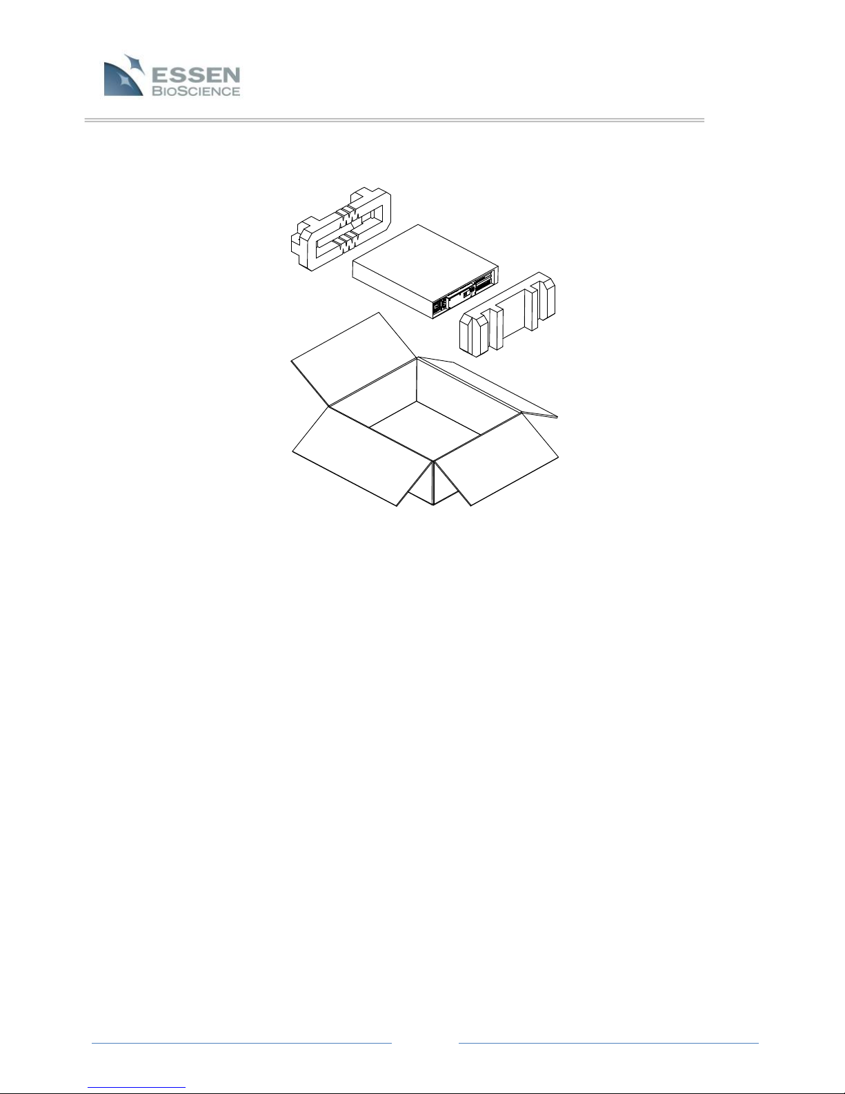
The IncuCyte™ZOOM System is shipped in two boxes, one containing the automated microscope
and the other containing the controller.
NOTE: The IncuCyte™ZOOM consists of 2 components; the controller and the microscope. The
controller remains outside the cell culture incubator, while the microscope is place inside the
incubator and holds the cells for monitoring. These two components are shipped in separate
boxes.
To unpack the microscope, start by setting the box with the correct side up on the floor or on a
sturdy bench top. Start removing materials from the top as shown in the exploded diagram
(Figure 1).

Page 9
IMPORTANT: Use only the AC power cord supplied or an equivalent cord with an IEC-320-C13
standard connector approved for operation at 5 amps and the appropriate voltage for your
local power. Also, ensure the local line voltage falls within the range printed on the
IncuCyte™ZOOM controller.
The microscope weighs approximately 44 pounds, so it is recommended that one person hold the
box while a second carefully removes the microscope from the bottom foam piece and places it
on a stable work surface. The unit should then be removed from its plastic bag (not shown in
Figure 1) and inspected for any obvious signs of external damage.
The controller should be removed from its box and bag in a similar fashion (see Figure 2). The
controller box will contain the controller and, under most circumstances, it will also include a
power cord appropriate for your local utilities. However, while Essen provides power cords
compatible with most utilities, there will be instances in which Essen does not stock the
compatible cord. In these rare circumstances, the purchaser will have to provide their own cord.
Figure 1. IncuCyte™ZOOM Microscope Packaging
Page 10
If the device is damaged in shipping, please call Essen BioScience immediately. You may then be
asked to return the unit.
Chapter 3: Installation of the IncuCyte™ZOOM Hardware
3.1 IncuCyte™ZOOM Hardware Features
The diagrams below (Figure 3 and Figure 4) identify many of the hardware features (buttons,
connections, indicators and displays) that will be referenced throughout this manual.
Figure 2. IncuCyte™ Controller Packaging

Page 11
Figure 3. Controller front view with access door open
Figure 4. Microscope front view
Page 12
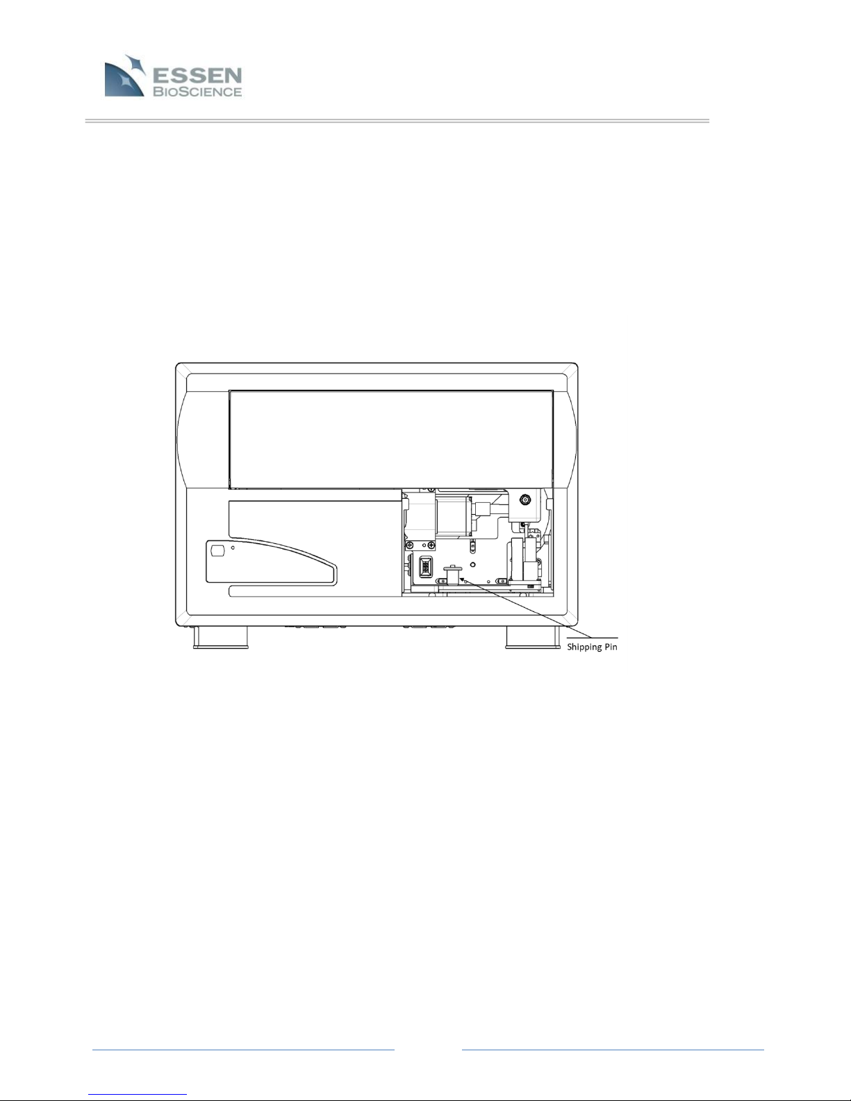
3.2 Removing the Shipping Pin
The IncuCyte™ZOOM ships with objectives and filter modules packed in a separate box. There is
also a shipping pin installed to lock the microscope in place. It must be removed before the
system installation can proceed. Remove the filter module access cover by pushing it down and
pulling the cover out. The pin will be visible as in Figure 5 below. To remove the pin, depress the
button in the center of the T handle and pull the pin straight up until it is free. Store the pin with
the other ZOOM accessories so that it can be reused if the system needs to be shipped to
another location or returned for service.
Figure 5. Microscope with access cover removed
Page 13
Figure 6. Microscope with shipping pin removed
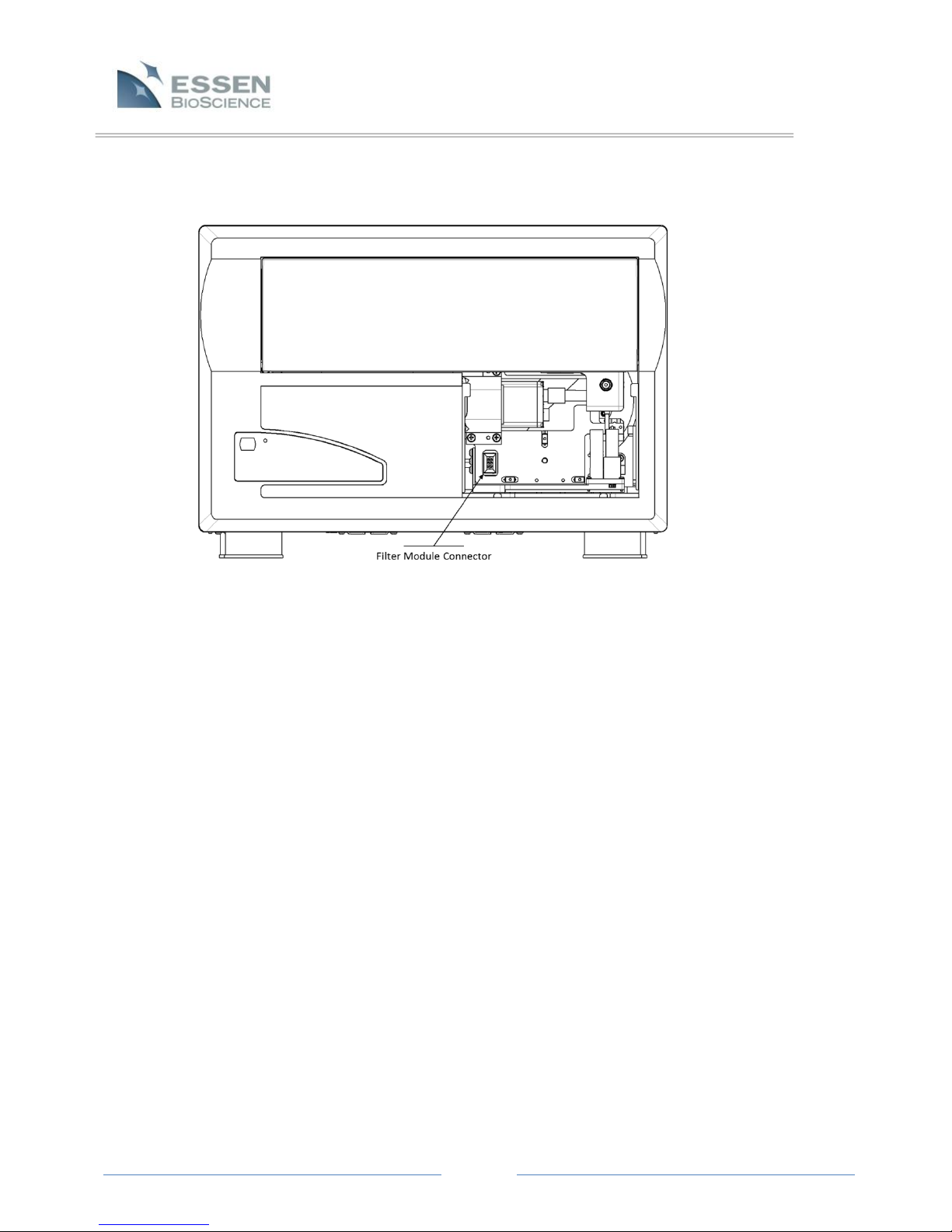
3.3 Installing the Filter Module
There are currently two types of filter modules available for your IncuCyte™ZOOM, one is for
systems that collect phase images only (no fluorescence) and the other allows collection of dual
wavelength fluorescence. One of these modules will have been shipped in the accessories box
with your ZOOM.
With the filter module access cover removed, pull out the drawer about halfway in order to get
better access. Remove the plastic cover from the filter module mount screw hole and place the
module into the microscope. Press the module into place such that the connector on the module
engages the connector in the microscope. The module can then be secured in place using the
2.5mm T handle hex (Allen) wrench supplied. Replace the plastic cover in the module mount
screw hole. See the diagram below ( Figure 7).

Page 14
Figure 7. Microscope with filter module installed
3.4 Installing an Objective
The IncuCyte™ZOOM ships with up to three objectives with magnifications of 4X, 10X and 20X.
The system will need to be calibrated for all of the purchased objectives. To get started, the 10X
objective should be installed if it is available, otherwise the 20X or 4X should be used. Objectives
are installed on a bracket that is shipped already installed in the system. See the diagram above.
With the filter module access cover removed, pull out the drawer halfway to provide access.
Remove the objective bracket from the system by loosening the screw using the supplied 2.5mm
T handle hex wrench and then pulling the bracket straight out. Finger tighten the objective into
the bracket. Install the bracket and objective back into the system on the two guide pins and
retighten the screw using the 2.5 mm T handle hex wrench. If you are installing a 20X objective,
verify that the corrective ring on the objective is set to 0.8. Close the drawer and replace the
filter module access cover.
3.5 Positioning the Controller
It is important to put the controller into position before placing the microscope into the
incubator. The controller should be placed on a level surface within 3 feet of the incubator's

Page 15
WARNING! The top cover of the microscope should NEVER be used as a shelf and should
NEVER be used to support a shelf.
IMPORTANT: After the microscope is placed in the incubator. Proceed IMMEDIATELY to the
next two sections. To avoid large amounts of condensation on the unit it is desirable to
connect and power the unit within a few minutes of installation.
cable port. The top of the incubator often works well. Do not, however, connect any of the
controller cabling at this point.
3.6 Placing the Microscope into the Incubator
When choosing a shelf for the microscope, keep in mind that flasks and plates are placed into the
IncuCyte™ZOOM cell drawer from above. For incubators that are at table height, a shelf
installed near the bottom of the incubator is usually most convenient. Approximately 12.5 inches
of height will be used by the instrument. In most incubators, this usually allows room for at least
two shelves to be installed above the microscope. Remove all shelves above the targeted shelf
before setting the microscope into the incubator. Feed the two cables from the microscope out
through the cable access port on the back or side of the incubator. The cables can usually be
routed up a corner of the incubator so as not to interfere with the installation of shelves above
the microscope. A split stopper supplied with the unit can be used to plug the access hole
around the cables. Shelves can be reinstalled above the unit as close to the incubators as the
mounting brackets allow.
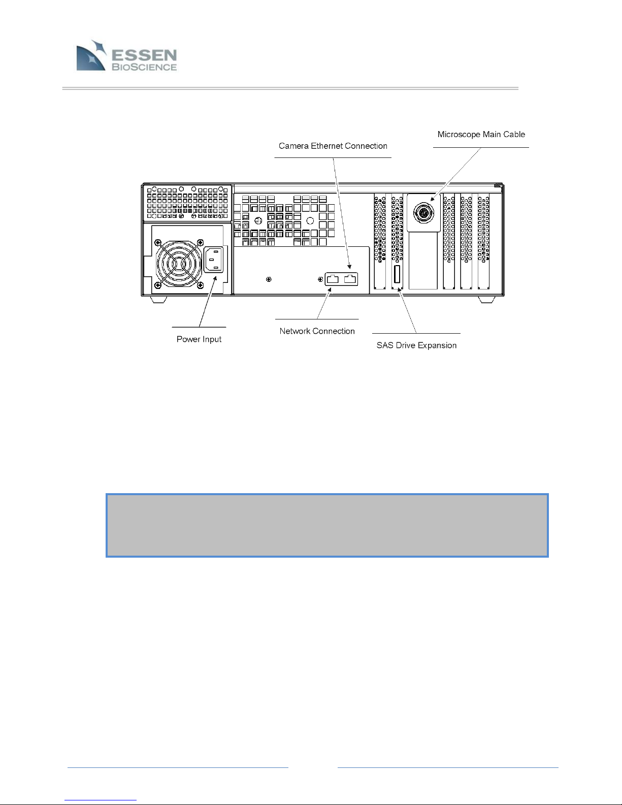
For connecting the cabling, see the rear panel of the IncuCyte™ZOOM controller (Figure 8).
There are two cables that connect the IncuCyte™ZOOM controller to the microscope. These
cables, which are fixed to the microscope, should be connected to the controller before the unit
is powered on. The larger, circular style plug on the microscope main cable should be connected
to the mating socket on the back of the controller. The second cable is a gigabit Ethernet
interface to the digital camera in the microscope and it should be plugged into the mating
connector labeled camera on the rear of the controller. The power cord for the unit can now be
installed. Use only the AC power cord supplied or an equivalent cord with an IEC-320-C13
standard connector approved for operation at 5 amps and the appropriate voltage for your local
power.
Page 16
IMPORTANT: The IncuCyte™ZOOM should be powered on immediately after installation into
the incubator. It is recommended that the unit be powered on at all times when it is in the
incubator to minimize the formation of condensation on the system. Proceed to the next
Section, Warming up the Microscope, to learn how to warm up the microscope.
3.7 Switching the IncuCyte™ZOOM On and Off
The power switch on the IncuCyte™ZOOM can be found under the front panel cover. The
system can be started or stopped by quickly depressing and then releasing the power switch.
When the system is running, it may take 30 to 60 seconds for the system to save any settings and
data before it powers down. If the system fails to power down, press and hold the power switch
for 10 seconds.
3.8 Warming up the Microscope
A warm-up cycle should be run to get all of the components in the system up to temperature
quickly and avoid condensation. After the system has been on for 2 minutes, the system will start
an auto warm-up. This will be indicated by a “Monitoring Temperature” message on the
controller LCD. The auto warm-up is NOT intended as a substitute for the manual warm-up cycle
but, rather, it is a backup process that occurs in those instances where the manual warm-up is
accidentally omitted.
Figure 8. Controller Rear Panel

Page 17
CANCEL the auto warm-up by pressing the “Stop/Eject” button on the front of the microscope
and start a manual warm-up. Use the LCD panel located on the front of the controller to start the
manual warm-up and follow the steps indicated below:
1. Click on the “Menu” button on the LCD screen and select the “Tools” option from the list on
the left.
2. Click on the “Warm-up” button from the newly displayed list of options.
3. Click on the “Go” button and select “Yes” to confirm that you want to start the warm-up.
The warm-up cycle will begin after a few seconds and will continue for approximately 45 minutes.
The green activity light on the front of the microscope next to the “Eject/Cancel”button will be lit
during the warm-up. A “Warming up” message will be displayed on the LCD in the top right
corner along with information of time remaining until the warm-up is complete.
3.8.1 Auto Warm-up
In the event that the manual warm-up process is omitted (for instance, if the IncuCyte™
ZOOM is temporarily removed from the incubator, and the person replacing it forgets to
run the manual warm-up procedure afterwards), then an auto warm-up process will be
initiated. The auto warm-up is NOT intended as a substitute for the manual warm-up
cycle but, rather, it is a backup process that occurs in those instances where the manual
warm-up is accidentally omitted.
When auto warm-up starts, the microscope is powered on and the front-panel LED lights
up until the camera achieves the requisite temperature. If the microscope is placed into
the incubator cold, then the auto warm-up process is automatically triggered. Auto
warm-up keeps the camera powered on for up to 45 minutes until it reaches a
temperature slightly above that of the standard incubator temperature. Auto warm-up
cannot occur if the controller is not powered on.
The auto warm-up cycle will be interrupted by scan. However, auto warm-up will resume
if the camera has not achieved its target temperature after the interrupting scan has
been concluded.
3.8.2 IncuCyte™ Controller Air Filter
The filter for the IncuCyte™ ZOOM controller is located behind the front panel (see Figure
9). Although this filter is easily accessible, it is NOT a consumable part, and Users should
not attempt to exchange it themselves. If there are any questions about this filter,
please contact Essen BioScience for more information.

Page 18
Chapter 4: Establishing Network Connections
The IncuCyte™ controller houses an embedded control computer that must be connected to your
network in the same way that ordinary PC’s running Microsoft Windows are connected. We recommend
that you consult with your IT department during the network connection, configuration and verification
processes. A standard Ethernet cable is used to connect the controller to a network hub or switch. The
unit is equipped with two network ports. The leftmost port is used as the primary network interface to
connect the IncuCyte™ controller to the network. The jack on the right is a port for the microscope
camera Ethernet cable. See Figure 8 for details.
The controller is configured at the factory for automatic assignment of its IP address on a network using
DHCP (Dynamic Host Configuration Protocol). Follow the procedures described in Section 4.1, DHCP
Based Networks to connect to this type of network. If the network is not configured to assign IP
addresses dynamically, then a static IP address must be assigned to the controller. See Section 4.2 (page
20), Static IP Based Networks, to reconfigure the IncuCyte™ controller for a fixed IP network.
4.1 DHCP Based Networks
Turn off power to the unit, and connect the controller’s primary Ethernet port to the network
with a standard Ethernet cable. Power on the controller and wait a few minutes before verifying
the controller is networked correctly.
If connected correctly, the controller will appear as a computer on the Microsoft Windows
Network as a member of the “Workgroup” group of computers. Assume that the controller is
assigned the name ZOOMXXXXX in the factory, where XXXXX is the 5-digit serial number of the
controller. This serial number is found on a label on side of the controller.
Figure 9. IncuCyte™Front Panel

Page 19
To verify that the ZOOMXXXXX controller has been successfully added to the network, a
Windows-based PC (hereby referred to as the “PC”) on the same network is required. These
verification methods are discussed separately for Windows Vista/7 and Windows XP PC’s.
4.1.1 Verifying the IncuCyte™ Controller Network Connection: Windows Vista or
Windows 7
1. Under the Windows “Start” menu, select “Network” (Vista) or “Computer”
(Windows 7).
a. Windows 7 only: On the left side of the window there is a list of
destinations (“Favorites”, “Libraries”, etc.). Look for the “Network”
destination and select this by left-clicking.
2. Look for the computer named ZOOMXXXXX (recall that XXXXX is the 5-digit
controller serial number). If you find it in the window, then the controller was
successfully added to the network, and you are done. If not, you should attempt to
find the controller on the network by continuing to the next step.
3. At the top of the window there is a text area that reads “►Network ►”. Left-click
in an empty area to the right of this text and type the following: \\ZOOMXXXXX
followed by the “Enter” key.
4. If the controller is found on the network, you will be prompted for a User name
and password. Press the “Cancel” button to exit. If the controller is not found,
then a “Cannot Find” message will be displayed after a brief search period.
4.1.2 Verifying the IncuCyte™ Controller Network Connection: Windows XP
1. Open “My Computer” from the PC’s Windows Start menu.
2. Under the heading “Other Places” on the left side of the window, open “My
Network Places.”
3. Under the heading “Network Tasks” on the left side of the window, click once on
“View workgroup computers.”
4. Look for the computer named ZOOMXXXXX (recall that XXXXX is the 5-digit
controller serial number). If you find it in the window, then the controller was
successfully added to the network, and you are done. If not, you should attempt to
find the controller on the network by continuing to the next step.
5. Verify that the “Address” toolbar is displayed at the top of the window. Under the
“View” menu time at the top of the window, verify that the “Toolbars - > Address
Bar” menu item has a check mark next to it.
6. Type the following in the “Address” box at the top of the window: \\ZOOMXXXXX.

Page 20
NOTE: This version of the IncuCyte™ Control Software is not backwards compatible with IncuCyte™
microscopes that are running earlier versions of the software. Contact Essen BioScience technical
support for instructions for updating controller software.
7. Click on the “Go” button to the right of the address bar. If the controller is found
on the network, you will be prompted for a User name and password. Press the
“Cancel” button to exit. If the controller is not found, then a “Cannot Find”
message will be displayed after a brief search period.
4.2 Static IP Based Networks
In order to reconfigure the IncuCyte™ ZOOM controller for a static IP address, a direct connection
must first be made to the controller. In order to accomplish this you will need to connect a
monitor, keyboard and mouse to the controller. To gain access to the monitor, keyboard and
mouse ports you need to unscrew the two screws on the back of the controller and remove the
back cover (See Figure 8).
With the controller powered down, connect the monitor, keyboard and mouse to the controller.
After connecting, power up the controller. Once Windows has booted up you can log in with a
User name "ZoomAdmin" and the Essen-provided password.
Recall that the ultimate goal is to configure the controller’s primary Ethernet port with a static IP
address selected for your corporate network. Once on the desktop, the controller’s primary
Ethernet port can be configured with a static IP address in the same way that the PC’s primary
port was configured. Use the Windows 7 instructions for the controller configuration. After
configuring the primary Ethernet port, log off of the controller’s desktop. Unplug the monitor,
keyboard and mouse from the back of the controller and reinstall the cover on the back of the
controller.
Chapter 5: Installation of the IncuCyte™ Control Software
The IncuCyte™ ZOOM control software is used to both configure the instrument to collect data and for
post-collection viewing and analysis of these data. This software is designed to run on PC’s running
Windows XP, Windows Vista or Windows 7 and requires an Administrator account to install.
Contact Essen BioScience Support (refer to section 2.3 for support contact information) to get the most
recent version of the software. Once downloaded, run the installer by double clicking on the installer
file.
5.1 IncuCyte™ Control Software Installation using Windows XP
1. Review the license agreement. To continue installation you must agree.
2. Select components you want to install.
3. Choose a destination folder and Install.
4. Install the Windows Media Player Codecs. (Required to save movies).
Table of contents
Popular Laboratory Equipment manuals by other brands


Appleton
Appleton AES1501 Operation manual

Jackson
Jackson AJX SERIES Installation quick guide

PermkinElmer
PermkinElmer NexION 300 ICP-MS manual

cytiva
cytiva Xuri W25 operating instructions

Dr. Brown's
Dr. Brown's Natural Flow Microwave Steam Sterilizer manual

Thermo Scientific
Thermo Scientific 3050 user manual


