Esta OILMAC 800 User manual
OPERATING INSTRUCTIONS
The World of Extraction
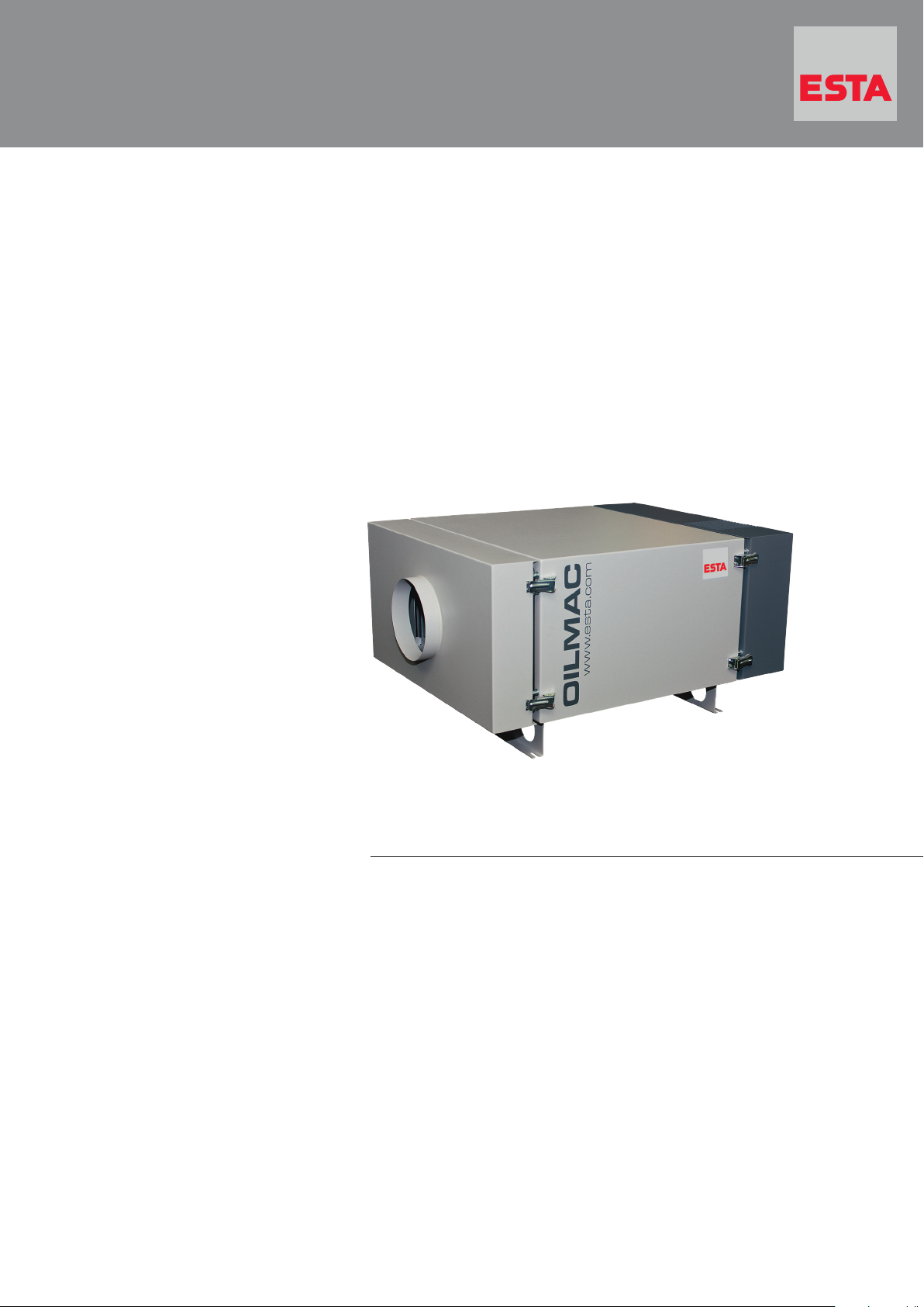
OILMAC
Oil Mist Extractor
Your purchase of an ESTA machine has
been a good decision. The design of
our quality products complies with the
latest state of the art. ESTA products
have been devised to provide for clean
air at the workplaces at which they are
applied. This results in an even more
enhanced level of quality and longer
machine times and, particularly, healthier
working conditions. Should you have
any questions pertaining to suction tech-
nology issues, please feel free to contact
us at any time. Our experts will be gladly
at your disposal.
Your ESTA Absaugtechnik Team
The World of Extraction
www.esta.com
Welcome to the sphere of suction
technology

Operating Instructions
OILMAC 800
OILMAC 1600
with backup filter stage H13
OILMAC 800 (order no.: 56201)
OILMAC 1600 (order no.: 56202)
with backup filter stage combination mesh
OILMAC 800 (order no.: 56211)
OILMAC 1600 (order no.: 56212)
Do not use this device unless you have
read the operating instructions and understood them.
Original operating instructions
56201-08-08

2
OILMAC
56201-52-08
Edition notice
Original operating instructions
Document no.: 56201-08-08
Publishing date: 11/04/2017
Type of device: OILMAC oil mist separator
Article no.: 56.201 // 56.202 // 56.211 // 56.212 and versions
Publisher
ESTA Apparatebau GmbH & Co. KG Tel.: +49 (0) 73 07 80 4 -0
Gotenstr. 2-6 Fax: +49 (0) 73 07 80 4 -500
Germany www.esta.com
Copyright notice (per DIN ISO 16016:2007-12)
Transfer or reproduction of this document, or the use or communication of its content, is forbidden
without explicit consent. Violators will be liable for damages. All rights to patent, utility or design
registration are reserved.

56201-52-08
OILMAC
3
Contents
Contents .................................................................................................................................3
1. General instructions........................................................................................................5
2. Product identification......................................................................................................6
2.1 Technical data .............................................................................................................6
2.1.1 With backup filter stage H13.................................................................................6
2.1.2 With backup filter stage combination mesh...........................................................7
2.2 Intended application..............................................................................................7
2.2.1 Ambient conditions ...............................................................................................7
2.2.2 Intended use .........................................................................................................8
2.2.3 Improper use.........................................................................................................8
2.2.4 Reasonably foreseeable misuse...........................................................................8
3. Product Description ........................................................................................................9
3.1 Picture of the device..............................................................................................9
3.1.1 OILMAC 800 .........................................................................................................9
3.1.2 OILMAC 1600 .......................................................................................................9
3.2 Separation and filter elements ............................................................................10
3.2.1 Pre-filter .............................................................................................................. 10
3.2.2 Backup filter stage ..............................................................................................11
3.3 Functional description .........................................................................................12
4. Safety instructions ........................................................................................................12
4.1 Hazard categories...............................................................................................12
4.2 Symbol explanation............................................................................................. 13
4.3 General safety instructions..................................................................................13
4.4. Preventing mechanical hazards ..........................................................................14
4.5 Preventing electrical hazards ..............................................................................14
4.6 Preventing material and substance hazards .......................................................15
5. Delivery and commissioning........................................................................................16
5.1 Delivery and transport .........................................................................................16
5.2Connection..........................................................................................................17
5.2.1 Electrical connection...........................................................................................18
5.2.2 Suction line connection.......................................................................................19
5.2.3 Siphon connection ..............................................................................................20
5.3 Function check.................................................................................................... 21
5.3.1 Rotation direction monitoring ..............................................................................21
5.4 Commissioning ...................................................................................................22
5.5 Troubleshooting during commissioning...............................................................22
6. Operating instructions ..................................................................................................23
6.1 Operating the device ...........................................................................................23
7. Maintenance & troubleshooting................................................................................... 23
7.1 Maintenance instructions ....................................................................................23
7.2 Inspection and maintenance intervals .................................................................25
7.2.1 Spare and wear parts .........................................................................................26
7.3 Cleaning and replacing the separation and filter elements..................................27
7.3.1 Cleaning and replacement intervals....................................................................28
7.3.2 Pre-separator......................................................................................................28
7.3.3 Pre-filter aluminium wire mesh............................................................................ 29

4
OILMAC
56201-52-08
7.3.4 Pre-filter filter pads.............................................................................................. 30
7.3.5 Pre-filter labyrinth filter........................................................................................ 30
7.3.6 Pre-filter labyrinth filter........................................................................................ 31
7.4. Backup filter stage filter element .........................................................................32
7.4.1 Backup filter stage H13....................................................................................... 32
7.4.2 Backup filter stage combination mesh ................................................................33
7.5 Siphon connection maintenance .........................................................................34
7.6 Cleaning filter and separation elements that can be cleaned.............................. 35
7.7 Clean the device .................................................................................................35
7.8 Store the device ..................................................................................................35
7.9 Troubleshooting .................................................................................................. 36
8. Disposal .........................................................................................................................38
8.1 Disposing of the separation and filter elements ..................................................38
8.2 Dispose of the device..........................................................................................38
9. Optional equipment....................................................................................................... 39
9.1 Start-up with potential-free contact .....................................................................39
9.2 Air vents ..............................................................................................................40
9.2.1 Connecting the discharge airline to discharge air ports ......................................41
9.3 Motor protection switch .......................................................................................41
9.4 Set-up on adjacent stand ....................................................................................41
9.5 Mobile design......................................................................................................42
9.6 Saturation display................................................................................................ 43
10. Declarationen.................................................................................................................44
10.1 Declaration of incorporation for incomplete machines pursuant to EC guideline
2006/42/EC, Appendix II, Part 1 B ......................................................................44
10.1.1 OILMAC 800 (without ESTA motor circuit breaker) ............................................44
10.1.2 OILMAC 1600 (without ESTA motor circuit breaker) ..........................................46
10.2 EU/EC Declaration of conformity for machines pursuant to EU/EC guideline
2006/42/EC, Appendix II, Part 1 A ......................................................................48
10.2.1 OILMAC 800 (with ESTA motor circuit breaker) .................................................48
10.2.2 OILMAC 1600 (with ESTA motor circuit breaker) ...............................................49
Notes.....................................................................................................................................50
Notes.....................................................................................................................................51
Notes........................................................................................................................................
56201-52-08
OILMAC
5
1. General instructions
Before operation, all persons who are to use the device or perform maintenance
on it must be provided with information, instructions and training in using the device
and on the substances for which it is to be used, including the procedure for safe
disposal of the collected material. Responsibilities must be clearly established for
the following:
Installation
Commissioning
Operation
Maintenance and repairs
Read the operating instructions carefully before working with the device.
The device must be used only by persons who have been instructed in its handling
and are explicitly authorised to use it.
Always keep the operating instructions at the place where the device is being used,
so that it can be seen by personnel at all times.
6
OILMAC
56201-52-08
2. Product identification
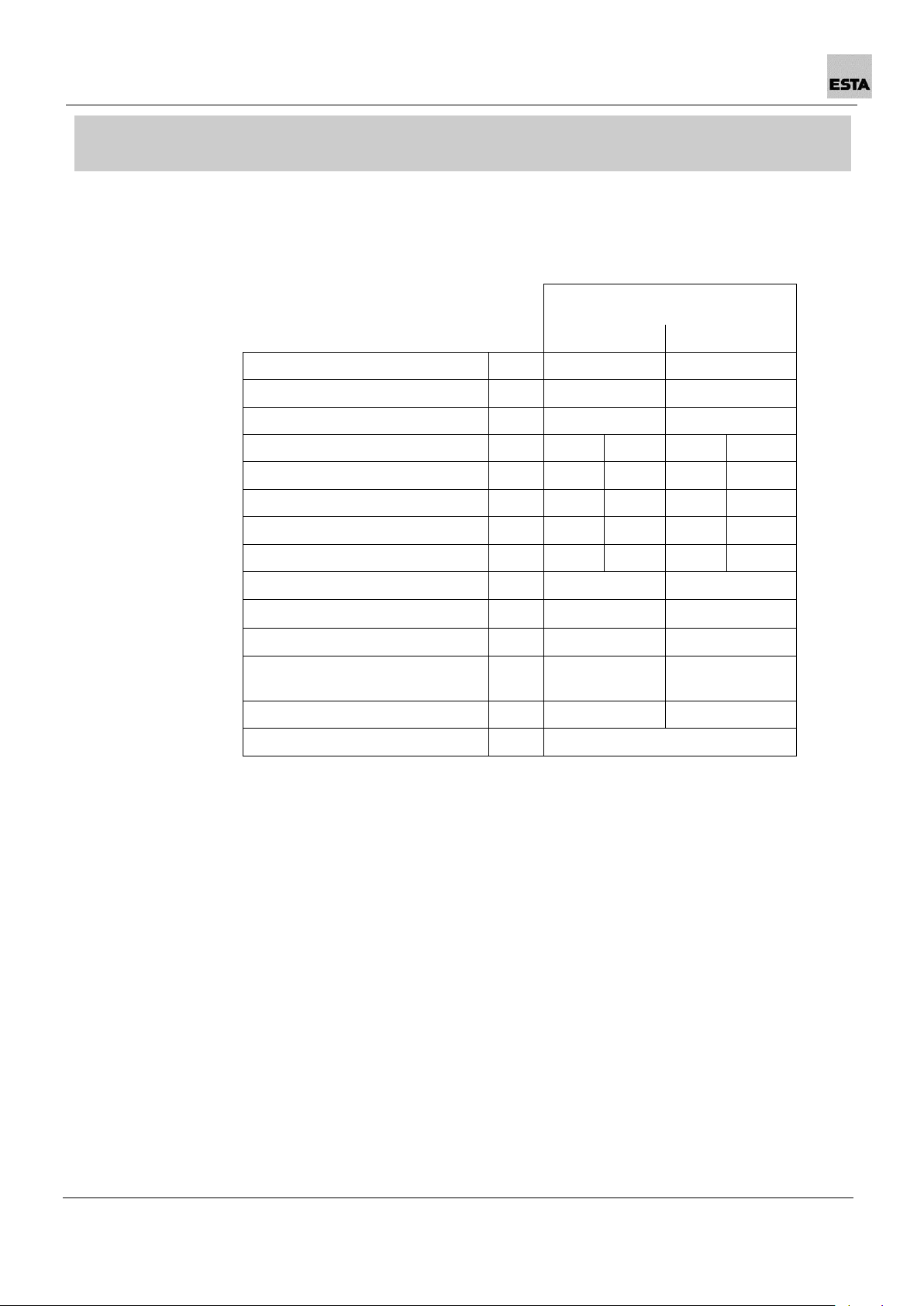
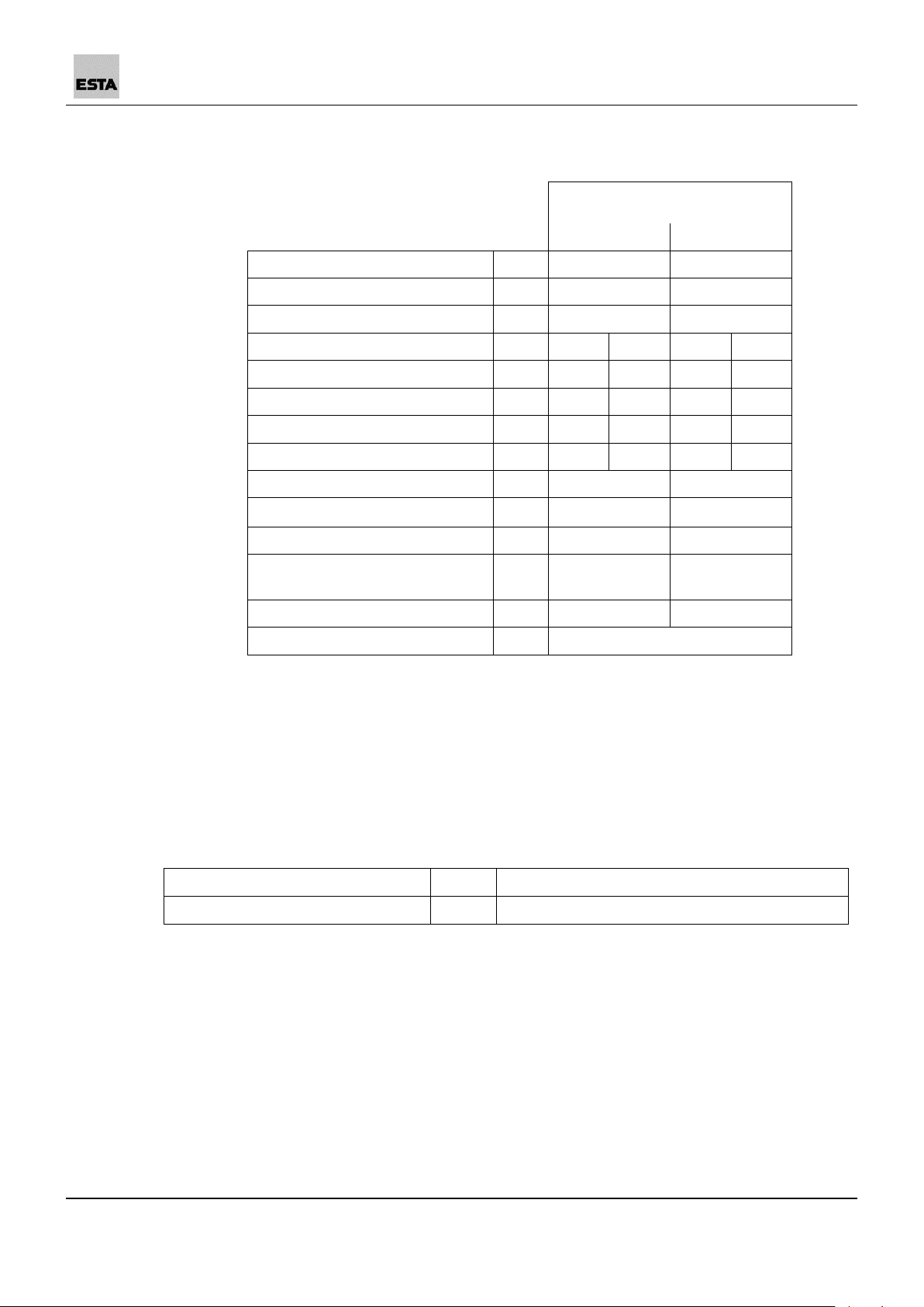
2.1 Technical data
2.1.1 With backup filter stage H13
We reserve the right to make technical
changes.
OILMAC
800
1600
Item no.
56201
56202
Max. volume flow
[m³/h]
840
1,800
Drive power
[kW]
0.55
**
1.1
**
Connection voltage
[V]
400
**
400
**
Nominal frequency
[Hz]
50
**
50
**
Nominal current
[A]
1.5
**
2.4
**
Circuit breaker
[A]
16
**
16
**
Protection class
IP 54
IP 54
Intake port ø
[mm]
200
250
Dimensions (L x W x H)
[mm]
1,140x685x475
1,270x685x805
Average sound pressure level
LpA
[dBA]
69
71
Weight
[kg]
approx. 80
approx. 130
Production year
See model plate
* Using the enveloping surface method DIN EN ISO 3744, measured at minimum volume flow; noise measurement margin
of error approx. 4 dBA
** Custom voltage on request
56201-52-08
OILMAC
7
2.1.2 With backup filter stage combination mesh
We reserve the right to make technical
changes.
OILMAC
800
1600
Item no.
56211
56212
Max. volume flow
[m³/h]
840
1,800
Drive power
[kW]
0.55
**
1.1
**
Connection voltage
[V]
400
**
400
**
Nominal frequency
[Hz]
50
**
50
**
Nominal current
[A]
1.5
**
2.4
**
Circuit breaker
[A]
16
**
16
**
Protection class
IP 54
IP 54
Intake port ø
[mm]
200
250
Dimensions (L x W x H)
[mm]
1,140x685x475
1,270x685x805
Average sound pressure level
LpA
[dBA]
69
71
Weight
[kg]
approx. 80
approx. 130
Production year
See model plate
* Using the enveloping surface method DIN EN ISO 3744, measured at minimum volume flow; noise measurement margin
of error approx. 4 dBA
** Custom voltage on request
2.2 Intended application
2.2.1 Ambient conditions
Ambient temperature
[°C]
+5 +40
Rel. humidity
[%]
30 - 70

8
OILMAC
56201-52-08
2.2.2 Intended use
The device has been manufactured based on state-of-the-art technology and
according to recognized safety regulations and must be used as intended:
For commercial use, such as in industrial enterprises and workshops.
For the separation of aerosols (e.g. cooling lubricant) which arise during the
mechanical processing of metallic parts.
For installation on a processing machine.
Approved for air recirculation operation with backup filter stage H13.
Approved for air extraction operation with backup filter stage combination
mesh.
Other applications are considered unintended use. ESTA is not liable for damages
due to unintended use!
The manufacturer sets up the device according to the operator’s information.
2.2.3 Improper use
The device has been manufactured according to the state of the art and recognized
safety regulations. Unintended use may cause hazards.
Therefore:
Do not use or store outdoors.
Do not change the location of the device during suction operation.
Do not set up or operate in dust/gas-explosive areas.
Do not use in painting operations.
Do not use in food operations.
Do not suck up aggressive gases.
2.2.4 Reasonably foreseeable misuse
Do not suck up hot embers, such as cigarette butts.
Do not cause complete closure of the suction openings.
56201-52-08
OILMAC
9
3. Product Description
3.1 Picture of the device
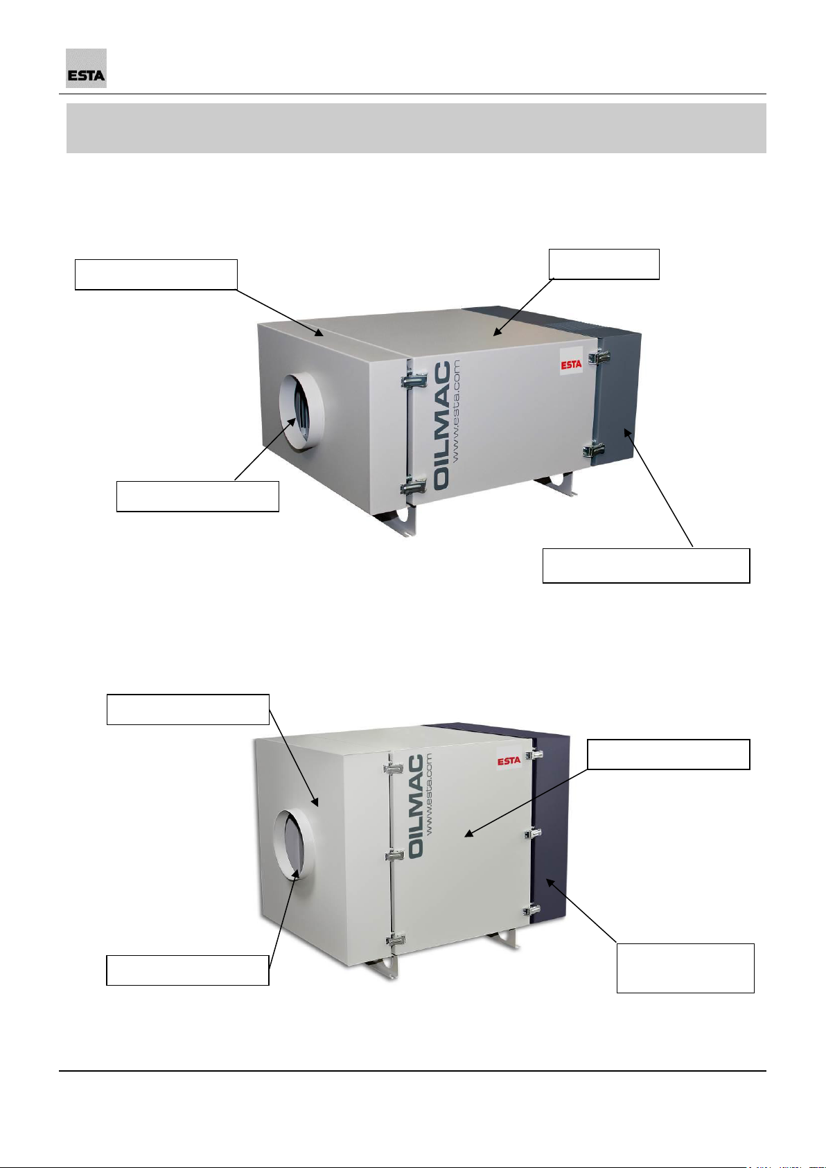
3.1.1 OILMAC 800
3.1.2 OILMAC 1600
Intake port
Fan unit with motor
Filter unit
Inlet element
Intake port
Fan unit with
motor
Filter unit
Inlet element

10
OILMAC
56201-52-08
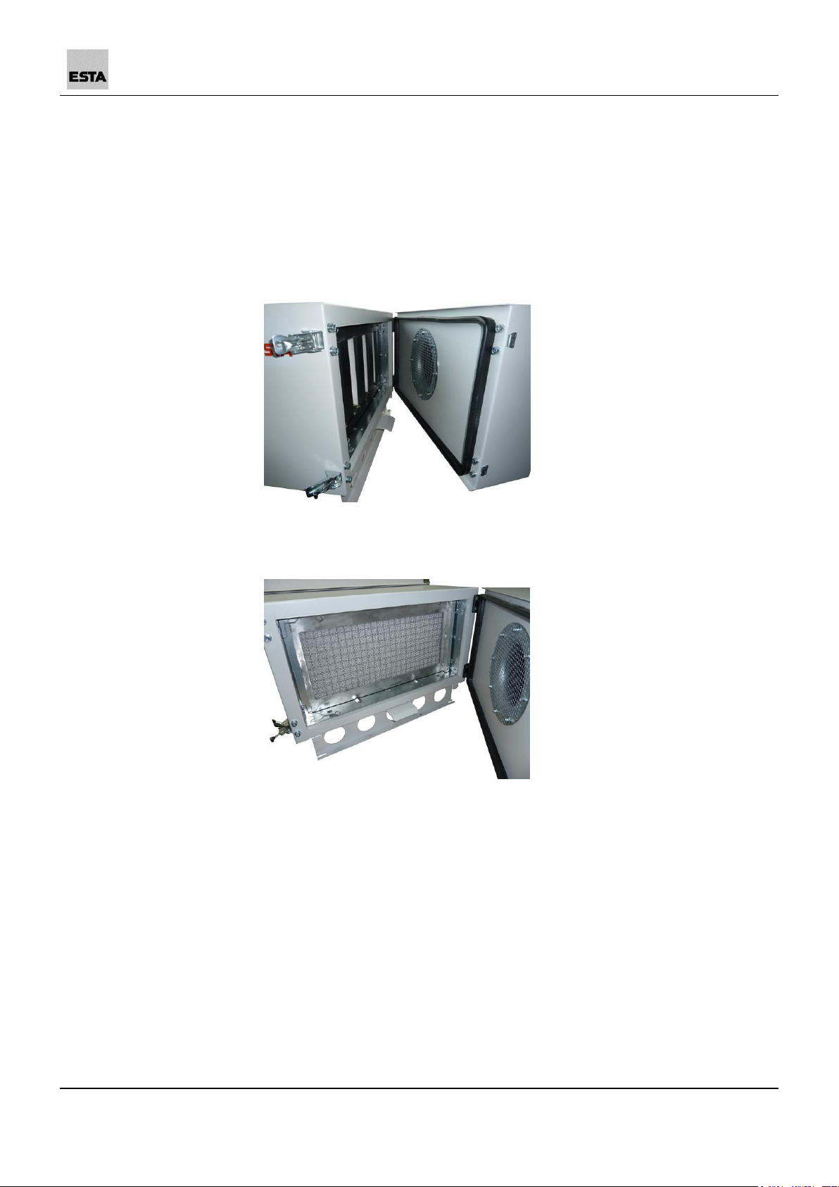
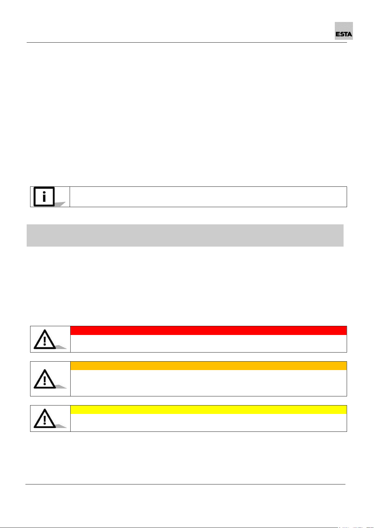
3.2 Separation and filter elements
3.2.1 Pre-filter
The separation and filter elements are designed so that the air is filtered
mechanically through several stages of filtration.
The pre-separator consists of the following filter elements:
1. Pre-filter metal mesh
2. Pre-filter fibre mat
3. Main separator labyrinth filter
4. Pre-filter fibreglass mat
1
1
2
3
2
4
56201-52-08
OILMAC
11
3.2.2 Backup filter stage
The separation and filter elements are designed so that the air is filtered
mechanically through several stages of filtration.
Depending on the design, the backup filter is designed as:
1. Backup filter stage H13
2. Backup filter combination mesh
12
OILMAC
56201-52-08
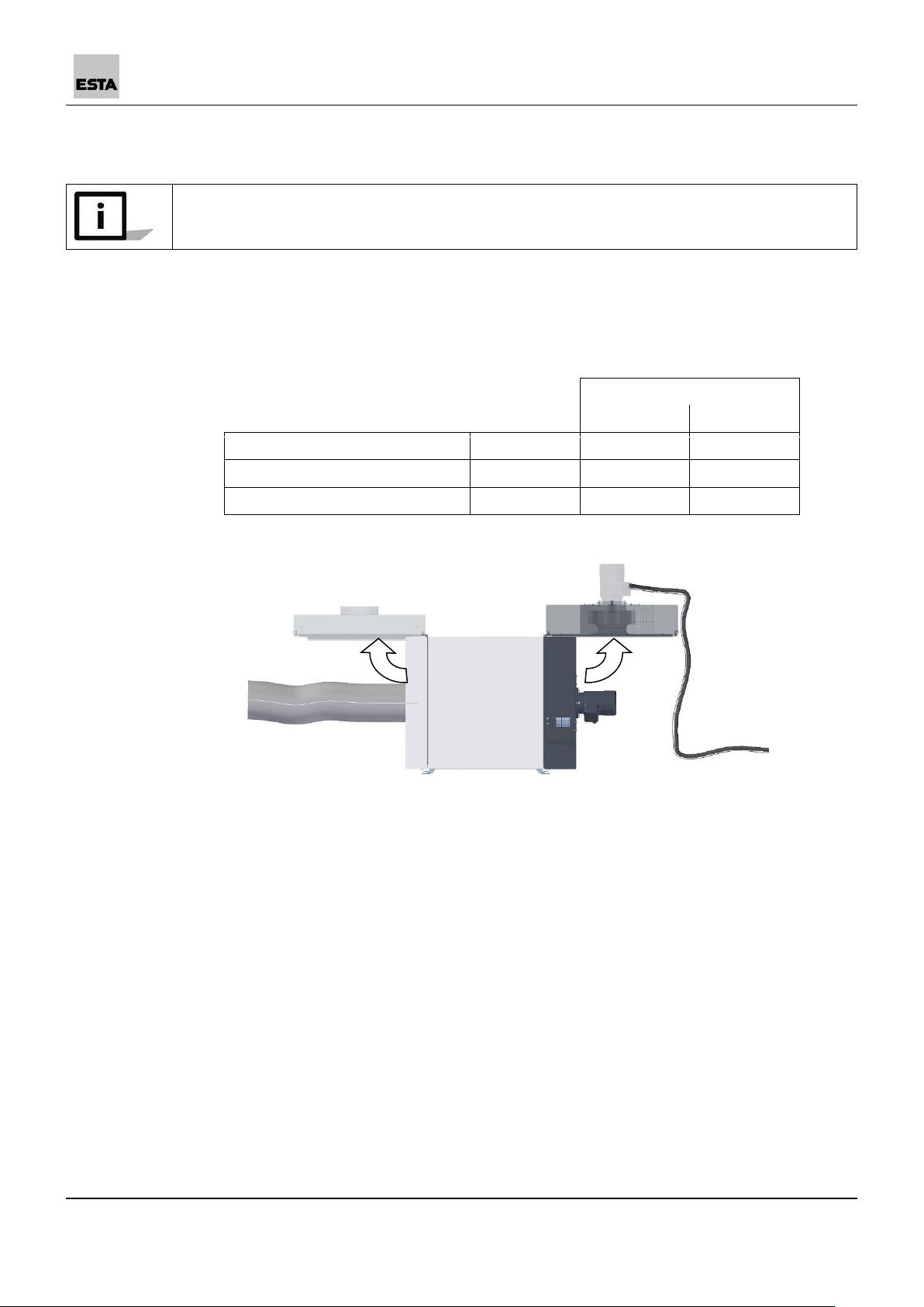
3.3 Functional description
The device is equipped with a three-phase motor which drives a radial fan.
Due to the negative pressure created by the fan, air containing oil and emulsion is
drawn from the processing machine through the suction hose connected to the
device's intake port. Filters located in the filter housing reliably separate dust
particles and oil and emulsion residue. The purified air is returned through outlet
openings (with backup filter stage H13) at the top of the device or a corresponding
discharge air line (the combination mesh with a backup filter stage.
The housing is designed so that separated, fluid oil and emulsion residue at the
bottom of the housing accumulate and can be drained through a siphon
connection.
Separated cooling lubricant can contain impurities which could negatively affect
machine availability in closed systems.
4. Safety instructions
4.1 Hazard categories
Safety instructions and cross-topic information are indicated in this manual by
symbols.
Based on the severity of the hazard, the hazard warnings are categorized as
follows:
DANGER
Hazard warning about an immediate danger to people.
Failure to comply can lead to severe injury or death.
WARNING
Warning about a recognisable hazard.
Failure to comply can lead to severe injury or death, and can destroy the device
or parts thereof.
CAUTION
Instruction about a hazard.
Failure to comply can lead to mild injury and to damage to the device.

56201-52-08
OILMAC
13
4.2 Symbol explanation
Further information
Reference to ESTA customer service
Reference to legal regulations
4.3 General safety instructions
During extraction, the volume flow returned from the device into the room should
be no more than 50% of the air supplied. With open room ventilation, supply air
flow should be assumed as equal to the room volume every hour. This means that
the rate of air replacement must be once per hour.
Supply air flow [m³/h] = room volume [m³] air replacement rate [1/h]
Example:
When the device is operating at the nominal airflow volume of 1,060 m³/h, the
same volume of fresh air must be supplied. This occurs with natural ventilation if
the volume of the work room is 1,060 m³ (e.g., 353 m² surface with a 3 m ceiling
height).
According to work equipment user directives 2009/104/EG and TRGS 560, safety
devices for prevention or removal of hazards must be regularly maintained and
regularly inspected by an expert for safe, flawless operation.
In all emergencies, disconnect the device from the power supply immediately.
If there is a fire, alert the fire department immediately, and contain the fire by
appropriate means. Therefore keep a suitable extinguishing agent near the device
before start-up and during operation.

14
OILMAC
56201-52-08
4.4. Preventing mechanical hazards
DANGER
Risk of injury posed by the drawing-in or catching of hair or loose items (e.g. chains,
hair, ties, etc.).
Observe the safety regulations for work on devices with rotating parts!
Before working on the device, turn it off and secure it against unintentional
reactivation.
When working on the device, tie back long hair or wear a hairnet!
When working on the device, do not wear any loose items (chains, ties, etc.).
WARNING
Crushing hazard due to loose or open covers
Keep covers closed during operation!
Before working on the device, turn it off and secure it against unintentional
reactivation.
Seal inspection openings securely after working on the device.
All movable machine parts driven by electric motors must be covered by fixed,
securely fastened protective covers that can be removed only with tools.
4.5 Preventing electrical hazards
DANGER
Electric shock from high voltages
Follow the safety rules for working with electrical devices!
Before working on the device, disconnect it from the voltage supply.
Any work on the electrical grid and on live components parts may only be
performed by an electrician.
DANGER
Residual hazard from loose or open covers
Keep covers closed during operation!
Any work on the electrical grid and on live components parts may only be
performed by an electrician.
All electrical parts must be covered by fixed, securely fastened protective covers that
can be removed only with tools. The device complies with Protection Class I
according to EN 60 335.
After use, before moving the device to another site and before cleaning,
maintenance, or replacement or removal of movable parts, switch off the device and
secure it from reactivation.
56201-52-08
OILMAC
15
4.6 Preventing material and substance hazards
CAUTION
Damage from improper handling of separated substances
Maintenance, cleaning, repair and emptying work must be done only by
expert personnel.
Observe the instructions of the cooling lubricant manufacturer about
handling these substances.
Absorb leaks with binding agents and dispose of them according to local
regulations.
Wear personal protective equipment.
- Gloves (impermeable and resistant to cooling lubricant)
- Aprons (impermeable and resistant to cooling lubricant)
- Protective clothing
- Respirator mask (particle filter class P3)
CAUTION
Damage from improper filter installation
Set up locally filtered forced-air ventilation where the device is being
maintained, inspected, cleaned or disposed of.
Operate the device only with the complete filtration system.
Always pay attention to the arrangement and installation location of the
filters.
Wear personal protective equipment.
- Gloves (impermeable and resistant to cooling lubricant)
- Aprons (impermeable and resistant to cooling lubricant)
- Protective clothing
- Respirator mask (particle filter class P3)
The people assigned to cleaning work must be instructed on the aspirated toxic
materials. Harm to bystanders and the environment must be prevented by all
means.
16
OILMAC
56201-52-08
5. Delivery and commissioning
5.1 Delivery and transport
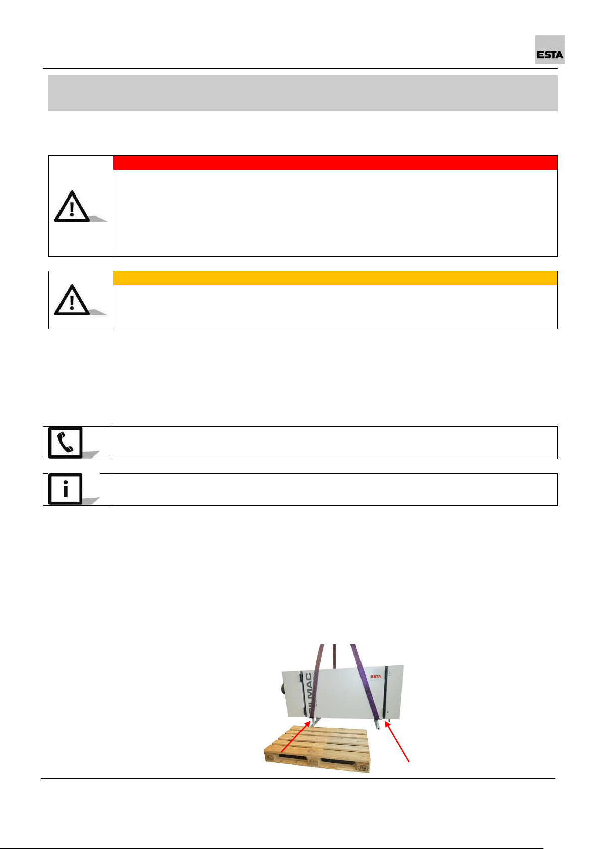
DANGER
Danger from falling device
Do not walk under heavy loads.
The lifting equipment must be designed for the weight of the device.
Only attach the lifting equipment to the marked points.
(See illustration)
Do not suspend from the motor.
WARNING
Crushing hazard if the device settles during transport
Secure the device during transport.
Wear safety shoes.
At delivery, the device is fastened to a pallet. Remove the protective cover and
floor securing devices. Inspect the delivery for completeness.
Please inspect the device for transportation damage when it arrives. Damage
determined must be reported and documented immediately.
ESTA customer service: +49 (0) 7307 804 - 0
Make sure the floor has adequate weight capacity and can be properly driven on
when transporting the device.
When transporting to the installation location, transport the device (leave pallet
secured below the device) with a forklift or lift truck.
To place it on the processing machine, use
suitable slings,
guide these under the device,
hang these on a suitable crane or the fork of the forklift. Also pay attention
here to the illustration!
56201-52-08
OILMAC
17
5.2 Connection
Before establishing cable connections between the device and the mains, check
whether the operating voltage specified on the rating plate matches that of the
mains.
The device must always be set up horizontally on a rigid, vibration-insulated
surface. Bolt the device tightly together with the processing machine.
In so doing, watch out for the minimum required clearances from ceilings and walls.
OILMAC
800
1600
Top of the device (air outlet)
[mm]
> 800
> 800
Fan unit
[mm]
> 800
> 800
Intake port
[mm]
> 800
> 800
18
OILMAC
56201-52-08
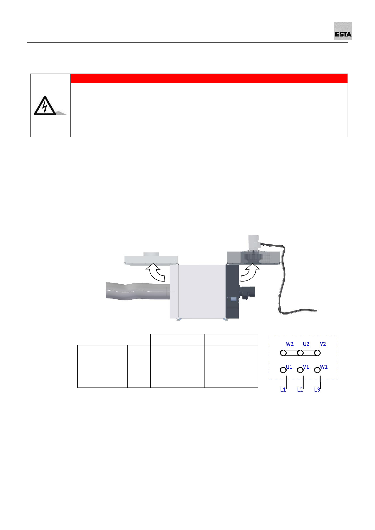
5.2.1 Electrical connection
DANGER
Electric shock from high voltages
Follow the safety rules for working with electrical devices!
Only operate the device with a suitable, lockable motor circuit breaker!
When working on the device, disconnect it from the voltage supply!
Any work on the electrical grid and on live components parts may only be
performed by an electrician.
The device power supply requires connection of a customer-side cable connection
with a slow-blow fuse and lockable motor protection switch to the device motor.
Connection to the building's power supply or a machine control cabinet is made
at the installation location.
The device is isolated from the mains during maintenance, cleaning and servicing
work via a lockable motor circuit breaker.
When choosing the cable length, remember that the ventilator unit needs to be
swung open for maintenance, cleaning and servicing work.
If the device is controlled on site via a control system, this must be designed so
that the oil mist separator starts up before the processing machine starts the
processing sequence. If the processing sequence has been completed, the oil
mist separator must continue running afterwards.
Domestic
Abroad *
Mains supply
Star
400 V; 50 Hz; 3
N~
Star
400V; 50 Hz; 3~
Fuse
[Amp.]
16 (slow-blow)
16 (slow-blow)
This manual suits for next models
3
Table of contents
Other Esta Scrubber manuals


