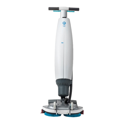
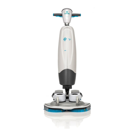
i-team co-botic 45 User manual

Service manual
i-team Professional b.v.
Hoppenkuil 27b, 5626 DD Eindhoven, The Netherlands
Telephone: +31402662400
Email: hello@i-teamglobal.com
Internet: www.i-teamglobal.com

3
Preface
Thank you for choosing the co-boticTM 45, the heavy-duty auto scrubber that cleans faster,
cleaner, safer, greener, and is better for everyone. The co-botic 45 compact design allows you
to clean right to any edge, minimizing manual scrubbing. The battery-operated
co-botic 45 is equipped with a brush that provides a deep scrub and a great cleaning result.
The co-botic 45 significantly reduces the amount of chemicals needed, which leads to a
greener result. It also reduces the risk of slippery floors. The co-botic 45 is coated to
withstand abrasive chemicals. This means it can be used at facilities like swimming pools.
i-link®
You can connect your cleaning equipment to i-link, the cloud-based management system. The
co-botic 45 has a small integrated transmitter, already connected to the i-link cloud. This
transmitter will send usage information, battery levels, and even the location of the machine
to the i-link cloud every day. It’s also possible to set rules for notifications (e.g. reminders for
maintenance after X hours of use) and to troubleshoot an issue with the machine through
your i-partner.
Please read this manual carefully for important information and operating instructions before
using the co-botic 45. Save this manual for future reference. This co-botic 45 will provide
excellent performance. The best results are obtained when the co-botic 45 is:
•Regularly maintained per the co-botic 45 preventive maintenance instructions in this
manual.
•Operated with reasonable care and caution.
•Maintained with manufacturer-supplied parts.
When this manual refers to “the manufacturer”, this means Future Cleaning Technologies
B.V., an affiliate company of i-team in Eindhoven, The Netherlands. When this manual
mentions “the partner”, this refers to your local i-team resell and support service partner.

4
Purpose of the service manual
The purpose of the service manual is to provide the service engineers with information
required to carry out both preventive as well as corrective maintenance. This manual can be
used as a guideline for repairs that can be done locally. If the machine cannot be repaired
with the guidance of this manual please contact your local sales person.
The service manual contains instructions regarding:
•personal safety;
•overview of the co-botic 45 functionalities;
•Troubleshooting overview
•Maintenance instructions;
•Storage conditions;
•Disposal of the co-botic 45.
These instructions must be considered to avoid risks that could lead to physical and/or material
damage.
Target audience
This service manual is intended for service engineers of the co-boticTM 45 and their
supervisors, as well as partners and importers.
Servicing of the co-botic 45
The co-botic 45 may only be service by a person who has correctly read and understood the
instructions in this manual and is trained by i-team.

5
Content
Preface .............................................................................................................................................................................................. 3
Purpose of the service manual ................................................................................................................................................4
Target audience.............................................................................................................................................................................4
Servicing of the co-botic 45......................................................................................................................................................4
Content .............................................................................................................................................................................................5
1Introduction ...........................................................................................................................................................................9
1.1 Documentation required ........................................................................................................................................9
1.2 Tools and equipment required ............................................................................................................................ 9
1.3 Materials required ....................................................................................................................................................9
2Safety warnings ............................................................................................................................................................... 11
2.1 Symbols used.......................................................................................................................................................... 11
2.2 General instructions ............................................................................................................................................. 12
3Transport and storage ................................................................................................................................................... 14
3.1 General ...................................................................................................................................................................... 14
3.2 Store position .......................................................................................................................................................... 14
3.3 Transport inside/outside ..................................................................................................................................... 15
3.4 Transport in a vehicle........................................................................................................................................... 15
4Technical specifications................................................................................................................................................. 17
4.1 Warranty................................................................................................................................................................... 18
4.2 Identification ............................................................................................................................................................ 18
4.3 Description ............................................................................................................................................................... 19
4.4 Remote control....................................................................................................................................................... 20
5Troubleshooting............................................................................................................................................................... 21
5.1 Possible problems................................................................................................................................................. 21
5.2 Report a problem via i-link®.............................................................................................................................. 23
6Scheduled maintenance................................................................................................................................................ 24
7Mid front cover and window panel assembly removal .................................................................................... 25
7.1.1 Disassembly.................................................................................................................................................. 25
7.1.2 Assembly........................................................................................................................................................ 26
8Removal of Top and Lower Head Panel Assembly........................................................................................... 27

6
8.1.1 Disassembly.................................................................................................................................................. 27
8.1.2 Assembly........................................................................................................................................................ 29
9Replacement of the Router.......................................................................................................................................... 30
9.1.1 Disassembly.................................................................................................................................................. 30
9.1.2 Assembly........................................................................................................................................................ 31
10 Replacement of the IMU .......................................................................................................................................... 31
10.1.1 Disassembly.................................................................................................................................................. 31
10.1.2 Assembly........................................................................................................................................................ 32
11 Replacement of the Ultrasonic sensor in the Lower Head Panel ........................................................... 33
11.1.1 Disassembly.................................................................................................................................................. 33
11.1.2 Assembly........................................................................................................................................................ 33
12 Replacement Ultrasonic sensor in the Mid Front Cover ............................................................................. 34
12.1.1 Disassembly.................................................................................................................................................. 34
12.1.2 Assembly........................................................................................................................................................ 34
13 Replacement of the Battery compartment door ............................................................................................ 35
13.1.1 Disassembly.................................................................................................................................................. 35
13.1.2 Assembly........................................................................................................................................................ 35
14 Replacement Power distribution board............................................................................................................. 36
14.1.1 Disassembly.................................................................................................................................................. 36
14.1.2 Assembly........................................................................................................................................................ 37
15 Replacement of the Network switch .................................................................................................................. 38
15.1.1 Disassembly.................................................................................................................................................. 38
15.1.2 Assembly........................................................................................................................................................ 38
16 Replacement of the Suction Motor...................................................................................................................... 39
16.1.1 Disassembly.................................................................................................................................................. 39
16.1.2 Assembly........................................................................................................................................................ 40
17 Replacement of the Water Pump ........................................................................................................................ 41
17.1.1 Disassembly.................................................................................................................................................. 41
17.1.2 Assembly........................................................................................................................................................ 42
18 Cleaning of the spraying nozzles ......................................................................................................................... 43
19 Replacement of a Caster wheel ........................................................................................................................... 44
19.1.1 Disassembly.................................................................................................................................................. 44
19.1.2 Assembly........................................................................................................................................................ 44
20 Replacement of a Drive wheel.............................................................................................................................. 45
20.1.1 Disassembly.................................................................................................................................................. 45

7
20.1.2 Assembly........................................................................................................................................................ 46
21 Replacement of the SIM-card tray....................................................................................................................... 47
21.1.1 Disassembly.................................................................................................................................................. 47
21.1.2 Assembly........................................................................................................................................................ 48
22 Replacement of the Cooling fan........................................................................................................................... 49
22.1.1 Disassembly.................................................................................................................................................. 49
22.1.2 Assembly........................................................................................................................................................ 49
23 Replacement of the In- and outlet tubes .......................................................................................................... 50
23.1.1 Disassembly.................................................................................................................................................. 50
23.1.2 Assembly........................................................................................................................................................ 51
24 Replacement of the Dirty water level sensor.................................................................................................. 52
25 Replacement of the ON/OFF relays switch...................................................................................................... 53
25.1.1 Disassembly.................................................................................................................................................. 53
25.1.2 Assembly........................................................................................................................................................ 54
26 Replacement of a Speaker...................................................................................................................................... 55
26.1.1 Disassembly.................................................................................................................................................. 55
26.1.2 Assembly........................................................................................................................................................ 55
27 Replacement of Brush motor................................................................................................................................. 56
27.1.1 Disassembly.................................................................................................................................................. 56
27.1.2 Assembly........................................................................................................................................................ 57
28 Replacement of the door for the brush cassette............................................................................................ 58
28.1.1 Disassembly.................................................................................................................................................. 58
28.1.2 Assembly........................................................................................................................................................ 58
29 Replacement of the Display ................................................................................................................................... 59
30 Replacement of the Control board of the display ......................................................................................... 60
30.1.1 Disassembly.................................................................................................................................................. 60
30.1.2 Assembly........................................................................................................................................................ 61
31 Replacement of the Spring operated suspension of a drive motor ........................................................ 62
31.1.1 Disassembly.................................................................................................................................................. 62
31.1.2 Assembly........................................................................................................................................................ 62
32 Replacement of Control board for the drive and lift motor........................................................................ 63
32.1.1 Disassembly.................................................................................................................................................. 63
32.1.2 Assembly........................................................................................................................................................ 64
33 Replacement of the Lift motor............................................................................................................................... 65

8
34 Replacement of the 2D Lidar sensor .................................................................................................................. 66
34.1.1 Disassembly.................................................................................................................................................. 66
34.1.2 Assembly........................................................................................................................................................ 67
35 Not enough suction.................................................................................................................................................... 68
36 Decommissioning and disposal ............................................................................................................................ 69
37 Attachments ................................................................................................................................................................. 70
37.1 Connection diagram ............................................................................................................................................. 70
37.2 CE Certificate........................................................................................................................................................... 71

9
1Introduction
1.1 Documentation required
The following documentation is needed for
repair procedures:
1. Technical documentation for specific
models. See the attachment in paragraph
37.1.
2. This service and maintenance manual
Figure 1
1.2 Tools and equipment required
For regular servicing of the co-botic 45, the following tools and equipment are required:
1. Screwdriver, torx and cross head;
2. Multimeter;
3. Heat gun;
4. Spanners;
5. Long nose plier;
6. Cutting pliers;
7. Soldering iron;
8. Torque wrench;
9. Allan keys (set).
1.3 Materials required
For regular servicing of the co-botic 45, the following materials might be required:
1. Various consumables (brushes, washers, various rubber O-rings, length of rubber tube Ø6
mm, different sizes bolt, nuts and torx screws);
2. Suction motor;

10
3. Various electronic panels (Power distribution board; Router; Control board of the drive
motor, Control board of the lift motor, Control board of the display etc);
4. IMU;
5. Ultrasonic sensor;
6. Drive wheel assembly;

11
2Safety warnings
Observe all applicable standards relating to the repair of electrical appliances.
Always disconnect the power plug from the mains before beginning repair work.
2.1 Symbols used
Symbol
Term
Explanation
WARNING
Indicates a hazardous situation which, if the safety
instructions are not followed, can lead to injuries of
the operator or bystanders and light or moderate
damage to the product or the environment.
CAUTION
Indicates a hazardous situation which, if the safety
instructions are not followed, can lead to light and /
or moderate damage to the product or the
environment.
ATTENTION
Indicates a liability situation, where the
manufacturer or its partners and affiliates cannot be
held accountable for damages caused by non-
compliance.
BATTERIES
Indicates a battery-operated machine, batteries
must be charged according to the instructions in the
separate class I battery charger user manual.
Batteries must be disposed of according to your
local laws and regulations.
SLIPPERY SURFACE
Indicates that the machine can cause floors to
become slippery. In the workplace, it is advised to
place slippery surface signs in these areas.
WEARING GLOVES
Indicates that when carrying out this task, ESD anti
static gloves should be worn.

12
2.2 General instructions
WARNINGS
.
•Maintenance on this machine should only be carried out by persons trained and
certified by i-team.
•Before carrying out any maintenance/repair, remove the batteries as described in user
manual.
•Electronic component can easily be damaged by Electro Static Discharge (ESD). To
protect the electronic components always wear ESD anti static gloves when working
on electronic components or mainboards.
•Use only for this machine specially developed batteries on the Co-botic 45. Using
other batteries will void the warranty.
•When replacing parts, only certified spare parts supplied by i-team should be used.
Using non-certified parts will void the warranty.
•When replacing cables make sure the replacing cables have the same diameter as the
original ones (AWG standard).
•The co-botic 45 is a heavy machine. When needed always use two persons to lift it.
•The temperature of the water used in or on the co-botic 45 should be below 40 oC.
Using water with a temperature above 40 oC. will do damage to the unit.
•Do not clean the machine with direct jets of water or pressure.
•When using a detergent for cleaning the co-botic 45, assure the pH should be in the
range of between 3 and 10.
•Do not operate this machine in environments where there are harmful, hazardous,
flammable, and/or explosive powders, liquids or vapors.
•Keep sparks, flames and incandescent material, away from the batteries. When
charging the batteries, perform the operation only in well ventilated areas and away
from naked flames.
•Remove all jewelry when working with electrical components.
•Before performing any maintenance/repair, carefully read all the instructions relevant
to the maintenance/repair.
•Do not leave the machine unattended without making sure that the machine itself
cannot move independently.
•Do not remove or alter the plates affixed to the machine by the manufacturer.
•To reduce the risk of fire, electric shock, or injury during maintenance, always remove
the battery and empty both the clean- and dirty water tank.

13
•Take the necessary measures to ensure that hair, jewelry and/or other loose parts can
be caught by any moving parts of the machine.
•Before transporting or storing the machine always empty the clean- and dirty water
tank. Doing so will avoid problems that might occur with temperatures below freezing
point.
•When it is necessary to tilt the machine for maintenance, remove the batteries and
both water tanks from the machine.

14
3Transport and storage
3.1 General
CAUTION
Always keep the main body of the co-boticTM 45 in the upright position. Make
sure the clean water tank and recovery tank are part of the main body during
transport.
Before storage or transport, drain the machine. Remove the battery after each use.
3.2 Store position
The correct store position is the upright vertical position. When stored, the clean water tank
and recovery tank should be installed in the main body.
TIP: Dry the tanks
Slightly open both tank caps before storage to allow the tanks to dry.

15
3.3 Transport inside/outside
CAUTION
The wheels of the co-botic 45 are not designed to roll over dirty surfaces. Sand
can cause the wheels to block. Lift the co-botic 45 while moving it from one
building to another.
CAUTION
The co-botic 45 is heavy. Do not try to carry the unit by yourself. You should
always use someone's help.
CAUTION
The handle shown in figure 2, pos. 1 is meant to push the machine. Never use the
handle to lift the machine.
When transporting the co-botic 45 inside:
1. Put the co-botic 45 in store position.
2. Move the co-botic 45 to its destination
using the handle (Figure 2, pos. 1), or the
carrying handle on both sides
(Figure 2, pos. 2).
When transporting the co-botic 45 outside:
1. Put the co-botic 45 in store position.
2. Carry the co-botic 45 to its destination,
using the carrying handle on both sides
(Figure 2, pos. 2).
Figure 2
3.4 Transport in a vehicle
The co-botic™45 is a compact machine and fits in the trunk of your car. Before loading the
co-botic 45 into your vehicle, make sure that:
•Both tanks are part of the main body.
•Both tanks are empty.
•The battery is removed.
Do the following:
7. Put the co-botic 45 in store position, see section 3.2.
CAUTION
The co-botic 45 is a heavy machine. When needed, always use two persons
to lift it.

17
4Technical specifications
Figure 3
Cleaning efficiency:
Roller Scrubber/dryer ~ 1500 –2500 m²
(Single Operation Cycle)
Cleaning pressure:
2-6 kg
Clean water tank capacity:
10 L
Recovery tank:
10 L
Battery Life:
~ 2 –3 hours (1x i-power 20)
Charging time:
~ 2 hours (i-charge 9c)
Sensors:
3D LiDAR (x1)
2D LiDAR (x1)
Cliff Detection Sensor (x1)
Ultrasonic Sensors (x4)
Display screen:
7 inches
Operational speed:
0.8 m/s (adjustable)
Noise level:
68/72/75 dB(A)
Weight:
35 kg
Dimensions (L x W x H):
500 x 504 x 629 mm
Brush speed:
300 –900 RPM
Others:
Remote control
Auto route planner
Co-botic management dashboard
Downloadable cleaning reports (pdf file)
Modular design on all parts

18
4.1 Warranty
The co-botic 45™should be used as intended and described in this manual. Using the
co-botic 45 outdoors will void the warranty on the product.
4.2 Identification
Each co-botic 45 has a unique serial number:
•Serial number (Figure 3, pos. 1).
•Production year (Figure 3, pos. 2).
•Production month (Figure 3, pos. 3).
•Production day (Figure 4, pos. 4).
Your i-team partner needs this number when
you order parts.
Figure 4
The serial number can be found on the inside
of the battery compartment lid
(Figure 5, pos. 1).
Figure 5

19
4.3 Description
The co-botic™45 consists of the following parts:
Figure 6
Legend
1.
Display
10.
Emergency stop
2.
Speaker
11.
Handle
3.
Ultrasonic wave radar
12.
Carrying handle
4.
Battery compartment
13.
Squeegee
5.
co-botic 45 main body
14.
Roller brush
6.
Remote control
15.
2D laser radar
7.
Clean water tank
16.
Cliff detection sensor
8.
SIM-card slot
17.
3D lidar sensor
9.
Recovery tank compartment

20
Figure 7
Figure 8
Legend
1.
Top Head Panel Assembly
4.
Lower Head panel Assembly
2.
Window Panel Assembly
5.
Clean water tank
3.
Mid Front cover
6.
Bottom Assembly
4.4 Remote control
The remote control consists of:
1. Antenna
2. Joystick
3. Power button
4. Connect button
5. On/Off indicator
Figure 9
Other manuals for co-botic 45
1
Table of contents
Other i-team Scrubber manuals