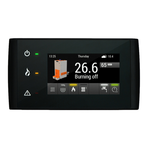
Estyma iGNEO COMPACT User manual

BOILER CONTROLLER
COMPACT

page 2
PL20110629

Index
Index
1 General information 5
1.1 Introduction 5
1.2 Features 5
1.3 Safety precautions 7
1.4 Disposal of old equipment
2 Connecting to the system 9
2.1 General requirements 9
2.2 Location 9
2.3 Assembly 10
2.4 Connecting 11
2.4.1 Direct connection of devices.............................................................................11
2.4.2 Connecting using burner wire...........................................................................13
3 Overview of the basic functions 15
3.1 Control panel 15
3.1.1 T e status LED............................................................................................... 15
3.1.2 Buttons......................................................................................................... 16
3.1.3 Grap ic display ............................................................................................. 17
3.2 Statuses of furnace 17
4 Handling 1
4.1 Navigation in the menu 1
4.2 Starting regulator - ON 1
4.3 Switching off the regulator - OFF 1
4.4 Time scheduling 19
4.5 Service password 20
5 Simple menu 21
5.1 Simple menu screens 21
6 Main menu 23
6.1 Heating 24
6.1.1 Selection of circuit.......................................................................................... 24
6.1.2 State............................................................................................................ 24
6.1.3 Settings........................................................................................................ 25
6.1.4 Time program................................................................................................ 25
6.1.5 Service......................................................................................................... 26
6.2 Hot water 2
estyma electronics
www.estyma.pl
page 3
PL20110629

Index
6.2.1 Selection of circuit.......................................................................................... 28
6.2.2 State............................................................................................................ 28
6.2.3 Settings........................................................................................................ 29
6.2.4 Time program................................................................................................ 29
6.2.5 Service......................................................................................................... 30
6.3 Buffer 31
6.3.1 State............................................................................................................ 31
6.3.2 Settings........................................................................................................ 31
6.3.3 Time program................................................................................................ 32
6.3.4 Service......................................................................................................... 32
6.4 Boiler 33
6.4.1 State............................................................................................................ 33
6.4.2 Settings........................................................................................................ 33
6.4.3 Service......................................................................................................... 34
6.5 Settings 35
6.5.1 Date and time................................................................................................ 35
6.5.2 Language...................................................................................................... 35
6.5.3 General settings............................................................................................. 35
6.5.4 Service......................................................................................................... 35
6.6 Burner 3
6.6.1 State............................................................................................................ 38
6.6.2 Settings........................................................................................................ 38
6.6.3 Service......................................................................................................... 39
6.7 Alarms 40
6.7.1 Alarm codes.................................................................................................. 40
6. Solar 46
6.8.1 State............................................................................................................ 46
6.8.2 Settings........................................................................................................ 46
6.8.3 Service......................................................................................................... 47
6.9 Info 47
7 Expansion of the system - CAN bus 4
7.1 Sonda Lambda 51
7.2 Solars 53
Specification 55
page 4
PL20110629

1 General information
1 General information
Thank you for choosing our product and congratulations on a good decision. We will be
grateful for comments concerning the unit’s performance.
ESTYMA electronics
Team
1.1 Introduction
Controller IGNEO Compact is a modern microprocessor system, w ic controls not only
t e boiler, but also t e central eating system and domestic ot water.
T e device controls t e burning process by providing t e appropriate amount of air and
fuel. By using solid state relays t e power of blower is regulated smoot ly.
T anks to t e advanced algorit m and possibility to regulation of many parameters, t e
system can be very flexible to adapt to t e needs of t e eating system.
1.2 Features
Graphic display – t anks to a large grap ic display FSTN andling device is intuitive.
Large fonts and icon - to improve ease of andling equipment for elderly people.
Two types of menus - menus simple and sop isticated. During t e daily operation of t e
device can support is easily accessible from t e simple menu.
Info button - t e controller is equipped wit t e function of intelligent assistance. Eac
parameter is described, calling t e description is done by pus ing t e info button.
estyma electronics
www.estyma.pl
page 5
PL20110629

1 General information
The modular construction of the CAN - using industrial CAN bus data exc ange (mainly
used in t e demanding automotive industry), it is possible to expansion of t e system. T e
maximum extension is 16 eating circuits, two circuits of ot water, energy buffers and solars.
Buffer - controlling t e eating system in combination wit eat storage reservoir.
Solars - t e controller controls t e solar system.
Powerful modern 32-bit ARM processor (ARM family is widely used in mobile p ones) -
enables advanced controlling algorit m device Fuzzy Logic II generation.
The history of alarms and errors - t e controller keeps a istory of t e last 20 errors and
alarms wit a description, date of creation and t e date of confirmation.
Clock with calendar - t e clock allows to program in a weekly cycle required temperatures in
t e rooms and ot water w ic contributes to a reduction in expenditure on fuel.
Statistics - in memory controller stores statistical data of t e system, so it is possible to
observe t e work and reduce fuel consumption. For example, monitoring temperature and
power boiler burner. Feeder operating time of t e fuel.
Beep sound alarm - built-in piezoelectric loudspeaker signals t e occurrence of an alarm in
t e boiler, w ic increases operational safety of t e device.
Resetting - function allows you to restore factory settings of t e controller.
page 6
PL20110629

1 General information
1.3 Safety precautions
Warning – risk of electric shock!
•Read t is operation manual carefully and t oroug ly before using t e unit.
•Keep t is operation manual and refer to it w enever you work wit t is unit in t e
future.
•Apply all t e rules and eed all t e warnings included in t e unit operation manual.
•Make sure t at t e unit is not damaged. In case of any doubts, do not use t e unit and
contact t e supplier.
•In case of any doubts concerning t e safe operation of t e unit, contact t e supplier.
•Pay special attention to all warning signs on t e unit casing and its package.
•Use t e unit as intended.
•T e unit is not a toy. Do not allow c ildren to play wit it.
•Under no circumstances c ildren s ould be allowed to play wit any parts of t e
package of t e unit.
•Access to small parts suc as clamping screws or bolts s ould be secured against
c ildren. Suc elements may be delivered wit t e unit and may result in c oking w en
swallowed by a c ild.
•Do not make any mec anical or electrical c anges to t e unit. Suc c anges may cause
t e unit to malfunction and fail to meet t e relevant standards, leading to an adverse
impact on t e performance of t e unit.
•Do not insert any objects into t e unit t roug openings (e.g. ventilation grills), as t is
may cause s ort circuiting, electric s ock, fire or damage to t e unit.
•Do not allow water, umidity or dust to enter t e unit, as t is may cause s ort
circuiting, electric s ock, fire or damage to t e unit.
•Provide adequate ventilation of t e unit, do not cover or block t e ventilation grills, and
ensure t at t ere is free flow of air around t e unit.
•T e unit s ould be installed indoors unless it is adapted for outdoor operation.
•Do not expose t e unit to mec anical impacts and vibrations.
•W en connecting t e unit to power supply, make sure t at t e parameters of t e supply
network are wit in t e unit’s operating range.
•All electrical connections must be as s own in t e electrical assembly drawings and
must comply wit national and/or local regulations concerning electrical connections.
estyma electronics
www.estyma.pl
page 7
PL20110629

1 General information
•T is unit contains no parts t at may be replaced by t e user. All maintenance work
except for cleaning, fuse replacement (w en t e unit is de-energized), and function
setting, s ould be performed by an aut orized service provider.
•Before doing any maintenance work, you must cut off t e power supply to t e unit.
•Do not clean t e casing of t e unit wit petrol, solvents or any ot er c emicals t at
may damage t e casing of t e unit. Using a soft clot is recommended.
1.4 Disposal of old equipment
T is electronic equipment is made of materials w ic are partly recyclable. T erefore,
w en t e equipment as reac ed t e end of its service life, take it to an electrical and
electronic equipment recycling centre or to t e manufacturer. T e equipment must not be
disposed of wit ot er ouse old waste.
page 8
PL20110629

2 Connecting to the system
2 Connecting to the system
2.1 General requirements
Read t is operation manual carefully and t oroug ly before you start using t e unit.
T e person installing t e unit s ould ave sufficient tec nical experience.
Copper wire connections s ould be designed to work in temperatures of up to +75ºC .
All connections made must be as s own in t e electrical wiring assembly drawings and must be
compliant wit national and/or local regulations concerning electrical connections.
WARNING !!! The de ice must be connected to a separate electrical circuit
equipped with an appropriately sized circuit breaker and residual current circuit breaker.
2.2 Location
T e unit is intended for indoor installation only. After selecting t e location, make sure
t at it meets t e following requirements:
1. T e location must be free from excessive umidity and from flammable or corrosive
vapours.
2. T e unit must not be installed near ig power electrical equipment, electrical
mac ines or welding equipment.
3. T e temperature in t e location must not exceed 60ºC and s ould not be lower t an
0ºC. Humidity s ould be wit in t e range from 5% to 95%, wit no vapour condensation
taking place.
estyma electronics
www.estyma.pl
page 9
PL20110629

2 Connecting to the system
2.3 Assembly
T e controller is designed for mounting in a wall or plate mounting. Plate t ickness
s ould not exceed 3mm. T e minimum dept of t e mounting ole is 100mm. T e dimensions
of t e ole and controller are indicated in t e figure below.
After placing t e panel in t e ole, always install t e mounting frame.
page 10
PL20110629

2 Connecting to the system
2.4 Connecting
T e device supply voltage is ~ 230V/50Hz. Plug t e power cord to t e controller in
accordance wit t e posted signs.
Be attac ed to t e controller for operating t e boiler sensors and actuators as needed.
T e drawings s ows t e connection sc eme of equipment. In t e tables, a description of t e
inputs and outputs.
Warning !!! Under no circumstances connect the protecti e conductor (PE) with a
neutral (N).
Warning !!! Wiring must be done with the de ice disconnected from the mains.
Connections should be exercised by a person possessing adequate powers in this regard.
2.4.1 Direct connection of devices
estyma electronics
www.estyma.pl
page 11
PL20110629

2 Connecting to the system
INPUTS
Description Explanation
Tboiler Boiler temperature sensor
Teg / p oto Ex aust gas temperature sensor or p otocell
Tburner T e temperature sensor burner
T w T e temperature sensor ot water
Troom Room temperature sensor / regulator (CTP)
Tc T e temperature sensor central eating
Tout Outdoor temperature sensor (CTZ)
12V +12V output to supply optional equipment
5V +5V output to supply optional equipment
GND Mass electric to connect sensors
OUTPUTS
Description Explanation
1 (CH) Central eating circulating pump
2 (HW) Circulating pump for ot water
3 (Ign) Burner igniter
4 (Mo) Opening t e central eating mixer
5 (Mc) Closing t e central eating mixer
6 (Blo) Burner blower
7 (Ftan) Feeder tank, or if burning wood, it's blower
8 (Fbur) Burner feeder
STB Protection STB
N Neutral standing
N1 Neutral separable suc as by STB
PE Protective
page 12
PL20110629

2 Connecting to the system
2.4.2 Connecting using burner wire
estyma electronics
www.estyma.pl
page 13
PL20110629

2 Connecting to the system
INPUTS
Description Explanation
Tboiler Boiler temperature sensor
5 (Teg) P otocell
6 (Tbur) T e temperature sensor burner
T w T e temperature sensor ot water
Troom Room temperature sensor / regulator (CTP)
Tc T e temperature sensor central eating
Tout Outdoor temperature sensor (CTZ)
12V +12V output to supply optional equipment
5V +5V output to supply optional equipment
7 (GND) Mass electric to connect sensors
OUTPUTS
Description Explanation
A (CH) Central eating circulating pump
B (HW) Circulating pump for ot water
4 (Ign) Burner igniter
C (Mo) Opening t e central eating mixer
D (Mc) Closing t e central eating mixer
3 (Blo) Burner blower
E (Ftan) Feeder tank, or if burning wood, it's blower
2 (Fbur) Burner feeder
1 (N1) Neutral separable suc as by STB
STB Protection STB
N Neutral standing
PE Protective
page 14
PL20110629

3 Overview of the basic functions
3 Overview of the basic functions
3.1 Control panel
3.1.1 The status LED
Status Importance
Green lig t continuously Controller OFF
Green blinks Controller enabled, burner OFF
Orange lig t continuously Controller enabled, burner enabled
Orange blinks Burner works
Red lig t continuously T ere is an alarm to be confirmed
Red blinks Alarm active
estyma electronics
www.estyma.pl
page 15
PL20110629

3 Overview of the basic functions
3.1.2 Buttons
Button Function
ON / OFF
Long press on t e main screen (>3 seconds) c anges t e state
of t e ON/OFF (on/off).
CH
Quick access to t e full configuration settings for t e central
eating.
HW
Quick access to t e full configuration settings for ot water.
INFO
S ows t e navigation information and descriptions of t e
regulated parameters.
ESC
Back one level up in t e menu, t e resignation of t e parameter
c ange.
Up arrow
Navigating t roug t e menus, increasing t e value of t e
parameter being edited.
On main screen, enter t e menu simple.
Down arrow
Navigating t roug t e menus, reducing t e value of t e
parameter being edited.
On main screen, enter t e menu simple.
ENTER
Access to t e menu.
Acceptance of c anges in t e value of t e parameter being
edited.
Confirmation of t e alarm.
page 16
PL20110629

3 Overview of the basic functions
3.1.3 Graphic display
3.2 Statuses of furnace
Status Description
TURNED OFF T e burner is not working. Permission to work off.
CLEANING Cleaning t e burner by strong stream of air.
FIRING UP Firing up fuel.
Providing t e initial dose of fuel to run igniter and blower.
INCANDESCING W en t e flame in p ase of t e firing up is discovered, starts
providing additional portions of fuel and increase t e power of
blower for arcing furnace.
POWER 1 T e burner works wit t e power first.
POWER 2 T e burner works wit t e power of a second.
MODULATION T e burner works wit a modulated power.
BURNING OFF Quenc ing of t e furnace. Work of burner and blower tray until
t e complete disappearance of t e flame.
STOP Burner does not work but it is to agree to is work. T e required
boiler temperature is reac ed.
estyma electronics
www.estyma.pl
page 17
PL20110629

4 Handling
4 Handling
4.1 Navigation in the menu
T e device as two types of menus: simple and main menus.
Simple menu - allows for quick access to basic controller functions. Enter t e menu is simple
by pressing t e "up arrow"or "down arrow" on t e main screen. Description of a simple menu
in c apter 5.
Main menu - allows you to access all t e functionality of t e controller (monitoring,
adjustments and service settings.) Access to t e main menu is done by pressing t e button
"Confirm, enter" on t e main screen. Description of t e main menu in C apter 6
Back to t e main screen is possible from any screen by pressing t e button "Back, esc" several
times.
WARNING !!! Access the ser ice is intended only for qualified technical personnel. The
changes may cause malfunction of the system.
4.2 Starting regulator - ON
To run t e controller (ON mode) for 3 seconds to press t e „ON / OFF” on t e screen
w en it is in t e OFF mode.
4.3 Switching off the regulator - OFF
To turn off t e controller (OFF mode) for 3 seconds to press t e „ON / OFF” on t e
screen w en e is in t e ON mode.
WARNING !!! When you turn off the controller, depending on the pre ious state, the
burner can still work (quenching), the state should not be interrupted. If the de ice is to be
excluded from the power supply, wait quenching process, until the status of the burner is
"off".
page 18
PL20110629

4 Handling
4.4 Time scheduling
Controller is equipped wit a clock and calendar. T is makes it possible to program t e
operation of individual circuit elements for eating depending on t e time and day of week.
Date and time are not reset during a power failure, because t e controller is equipped wit a
battery t at s ould be replaced every two years.
Programming takes place in t e menu of t e circuit (eg, ot water, eating, buffer) and
for eac item carried in t e same way.
Selecting the day of week. Upon entry in t e "Programme Time" day of t e week
flas es. Arrow buttons to select t e day you want to set or just c eck t e settings of t e
program.
Programming. After selecting t e day of week and approved "ENTER", indicator being
programmed ours flas es. At t e same time also displays t e time, and t e next to it icon
t at represents t e currently selected setting time (t e symbol of t e sun means comfort
temperature, t e moon is a symbol of t e economic temperature.) To move to t e next our,
press t e down arrow (economy temperature) or t e up arrow (comfort temperature). If t e
day is already programmed in accordance wit our wis , press "ENTER". After approved t e
c anges (or cancellation) will blink day of t e week.
T e figure s ows an example of t e preset day of t e week.
Temp. economy from 00:00 to 6:00
Temp. comfortable from 6:00 to 9:00
Temp. economy from 9:00 to 18:00
Temp. comfortable from 18:00 to 24:00
WARNING !!! Values of temperatures comfortable and economical are set in the
“SETTINGS” menu and may be different for each of the circuits. To make the time program
work, you must also enable a timed mode in the “SETTINGS” menu.
estyma electronics
www.estyma.pl
page 19
PL20110629

4 Handling
4.5 Service password
Access to t e service parameters are password protected. After entering t e correct
password, access will be lifted. Access to t e service parameters will be locked after a period of
10 minutes wit out pus ing buttons.
Service code is a temperature of t e boiler in menu BOILER / SETTINGS and
3 letters "EST".
Example: If t e temperature of t e boiler in menu BOILER / SETTINGS is 60 ° C,
password is “60EST”.
WARNING !!! Access the ser ice is intended only for qualified technical personnel. The
changes may cause malfunction of the system.
page 20
PL20110629
Table of contents
Other Estyma Controllers manuals
Popular Controllers manuals by other brands

Peak Sensors
Peak Sensors VERTEX F4 instruction manual
Raven
Raven SCS 460 Operator's manual
ADVATEK LIGHTING
ADVATEK LIGHTING PixLite E16-S Mk3 quick start guide
ECOTEX
ECOTEX LIT1304 quick start guide
NextWave Digital
NextWave Digital SHARK LCD user manual
Protectowire
Protectowire FiberSystem 8000 user guide
