LIT1304 Rev 051613
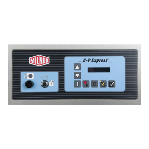
Ambient Ozone Monitor/Controller
Quick Start Guide
Installation Instructions
Step 1: Insure alarm dipswitches are set correctly. The unit will ship from the factory set to provide a 0.1ppm
high-limit set point. If a different set point is desired, remove the cover by unscrewing the screws on the
back, and set the dipswitch to configure the unit to the desired set point. See the drawing below.
Step 2: Mount the unit on a wall at least 7 feet off of the floor and as far away from the ozone generator and any
chemical storage areas as possible.
Step 3: Attach the Cat 5 cable’s RJ45 connector to the jack located on the bottom of the ambient
monitor/controller (cable is attached to the bottom of the EcoTex Ozone Generator).
For advance applications and troubleshooting, we have provided the pin designations for the RJ45
connector on the unit below.
1. +12VDC
2. Not Used
3. GND
4. Relay-2 (volt-free)
5. Relay-2 (volt-free)
6. Relay-1 (volt-free)
7. Relay-1 (volt-free)
8. GND
Operating Instructions
NOTE: Upon initial start-up (power applied to the EcoTex system), the monitor/controller will go into a 2
minute cleaning cycle.
The monitor/controller will provide a volt free “closed” loop on Relay-1 and Relay 2 when the ozone level is
below the high-limit set point. When connected to the EcoTex laundry system, this “closed” loop signal will
allow ozone to be generated. When the ambient ozone level is above the high-limit set point, Relay-1 and Relay-
2 will “open”, and ozone production will be interrupted. The Room Alarm LED on the front of the ozone
generator will illuminate and the ozone output LED’s will not be illuminated. Once the ambient ozone level
drops below the high-limit set point of the monitor/controller, the ozone generator will once again be allowed to
generate ozone.
