Eta COMPUTE TALIA User manual
TALIA
INSTALLATION GUIDE
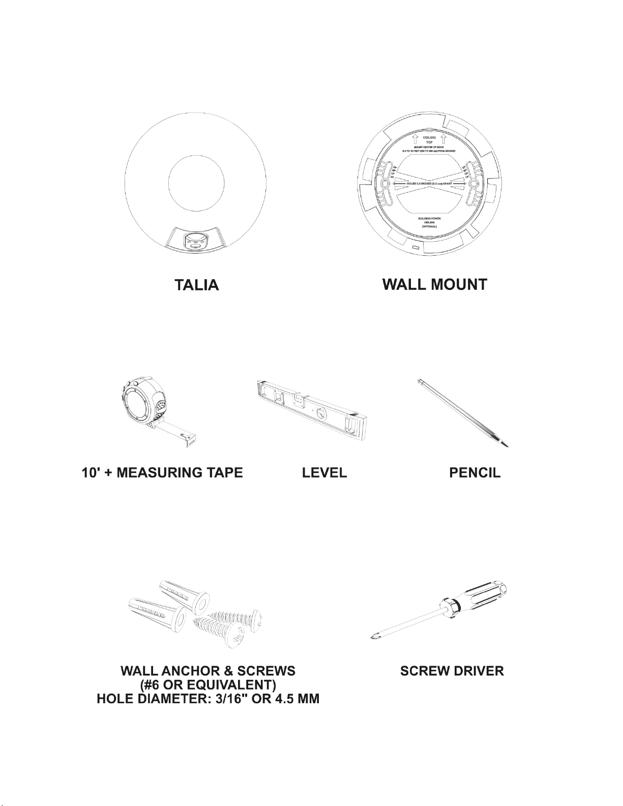
1. Included in package
2. Additional tools needed
3. Optional tools and hardware (not included)

4. Determine installation location
The Talia sensor is designed for single-wide doors in commercial offices
and other public spaces. Depending on the door configuration, there are
two categories of mounting position.
Case 1 (center)
Use center placement if there is no door mounted in the doorway, the
door opens outwards (outside of the room where the device is
mounted) or in the presence of a sliding door.

Case 2 (side)
In the case where a door swings into the primary space (inward opening
door), Talia must be mounted on the side opposite the door’s hinges, to
minimize interference in sensing by the door. Side placement can also be
used for doorways which reach the ceiling or any other situation making
center placement not possible.
Optimal and allowed mounting position of the Talia device above the
door. Lens should always point towards the doorway center point
Note that correct Talia placement ensures good performance in the case
where people enter through the door and then taking a hard left or right
turn (so their path ends up parallel to the one of the walls adjacent to
the doorway). This is a realistic scenario for conference rooms where a
conference room table and chairs may immediately block progress after
a person enters the room.

For optimal performance Talia should be mounted in one of the optimal
locations as indicated by shaded and white circles in figure 5. However,
if optimal placement is not possible (e.g., due physical obstacles or low
ceiling) Talia can be mounted within the allowed position zones. If using
the allowed position zones, for best performance Talia should be
mounted as close and possible to the optimal position.
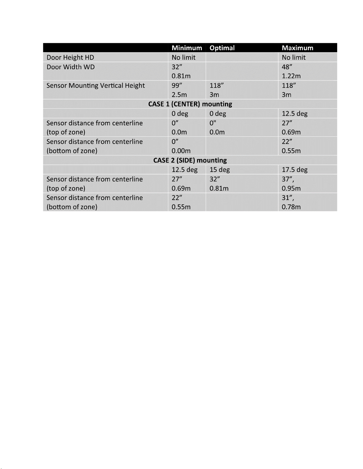
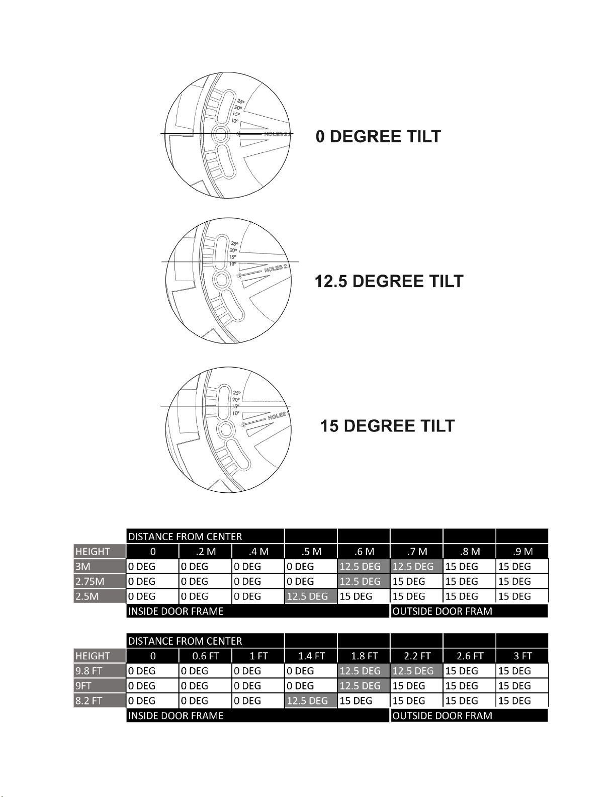
Mounting position chart
Rotation
Talia must be mounted with its primary sensing elements pointing
towards the center of the threshold of the monitored doorway.Talia
provides two methods to achieve this:
For optimal locations –predefined angle
Talia provides a simple method for mounting with the correct (0 or 15
degree) rotation at the shaded locations in figure 5. The simple method
doesn’t require any measurements or calculations other than those
needed to locate the shaded optimal location on the wall.

For other locations –variable angles
Talia also provides a more flexible method for mounting with the
correct rotation at any location within the allowed position zone
(hatched) in figure 5. This method requires additional distance
measurements and multiple steps to calculate and install at the correct
rotation angle.
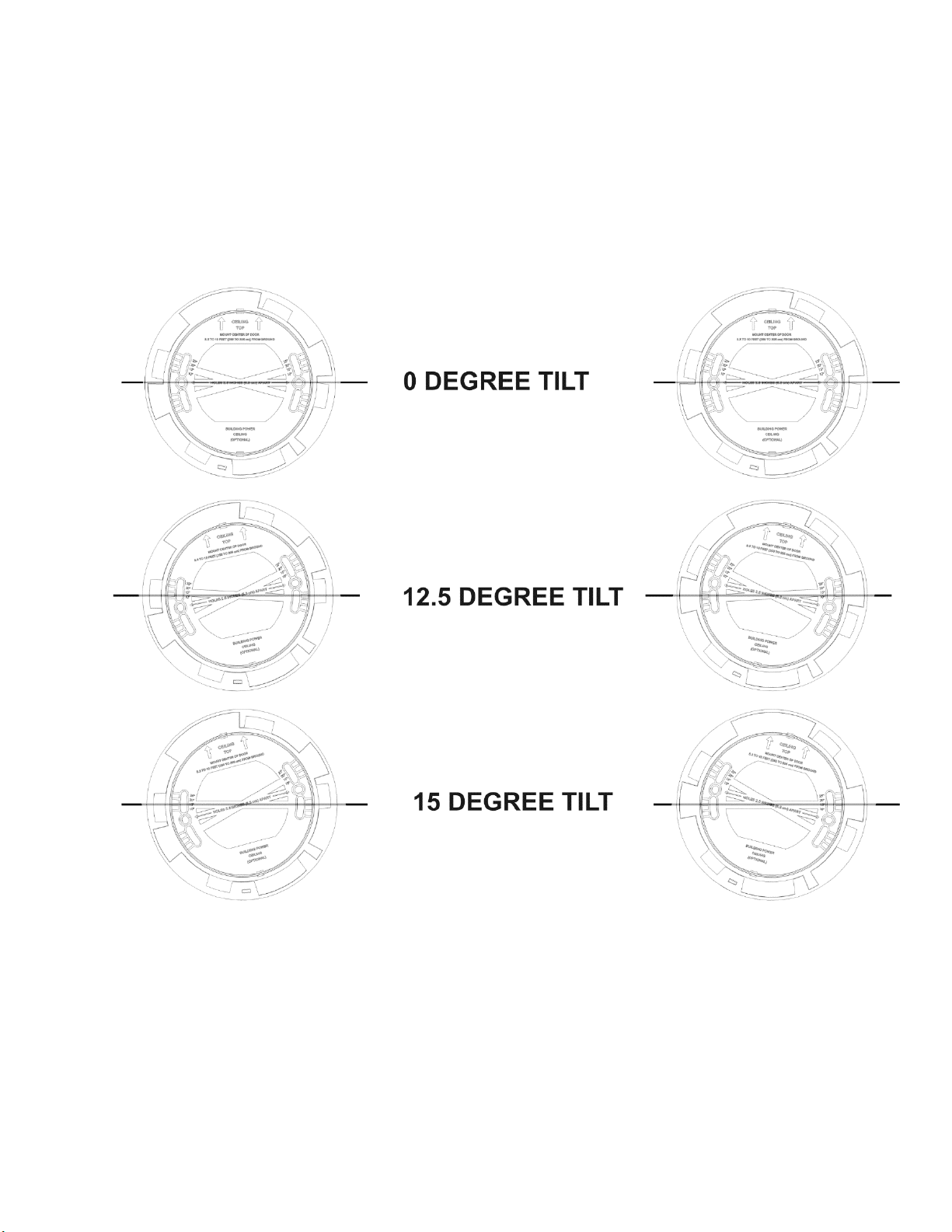
Tilt
For the sensing geometry shown above, the Talia must be tilted (with
the top tilted away from the plane of the vertical wall) to ensure that
Talia’s field of view includes the door threshold (the line of the doorway
at floor level). The Talia (with its mounting base) provides a built-in
fixed tilt, such that when mounted flush onto a vertical wall, the correct
field of view is achieved.
Illumination
To achieve low power consumption and long battery life, the sensors
will rely on externally sourced illumination.
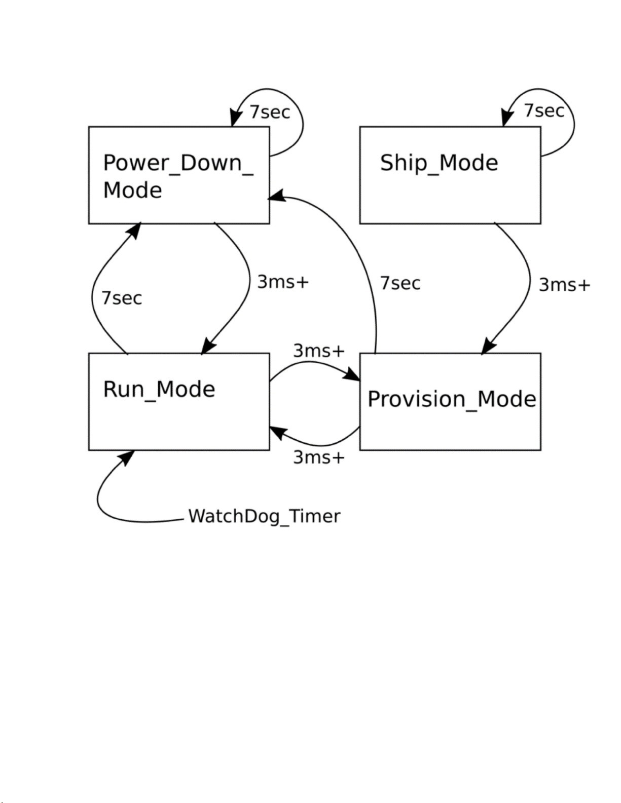
Commissioning and calibration
Talia is delivered in ship mode, with all circuitries powered down.
Typically, Talia will be provisioned in provision mode, and then put into
operation (run mode).
Once provisioned, Talia stays in run mode until a button press changes
its state.
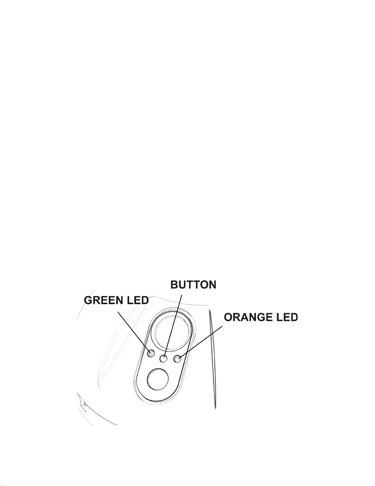
Talia modes are changed by pressing Talia’s hidden button. Two distinct
button-press lengths are supported –a long press, of at least seven
seconds, and a short press of less than 3 seconds. The power button is
located in the hole between the green and amber LEDs on the front of
Talia and can be accessed using a suitable tool.
The green LED is on steady for ten seconds when Talia exits power
down mode or ship mode. This indicates that Talia has been turned on.
The green led is pulsed at 1hz ten times when provision mode is
entered.
5. Mounting and installation
Using a level, draw a straight horizontal line at the height and location
determined in section IV.
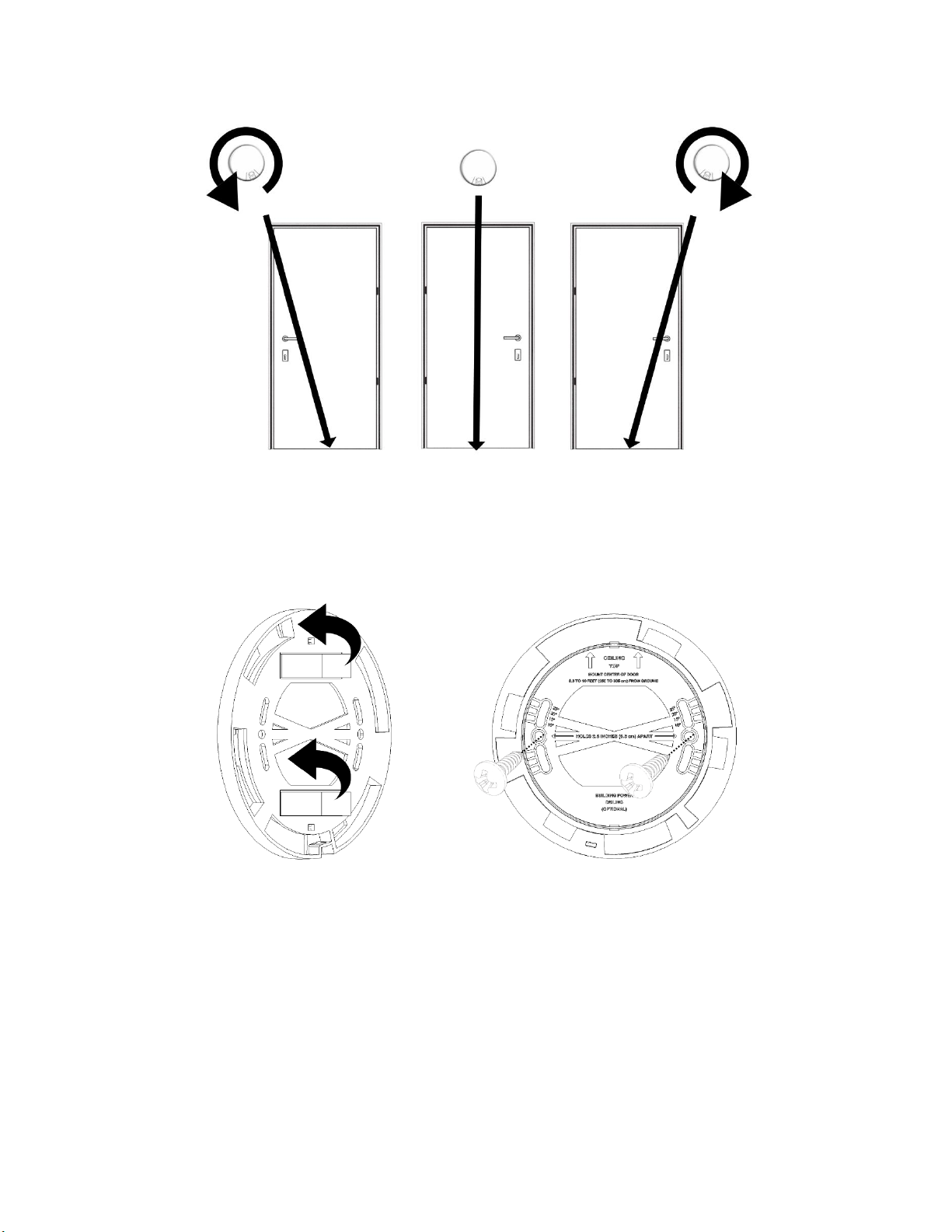
**Verify the base location and angle making sure Talia will point
towards the bottom center of the door.
Remove the tape peel from the wall mount and line it up with the
chosen angle on the wall. Press and hold the wall mount firmly against
the wall for 15 seconds. *Optional wall anchors and screws should be
placed 2.5 inches apart.

To attach Talia to the wall base plate: line up the four tabs on the
bottom of the device with the matching openings on the base plate.
Rotate the device clockwise until Talia "clicks" into place.

6. Dismounting
Dismount the Talia from its base by using a flat thin object, such as a
flat head screwdriver, to push down on the snap accessed by the space
in the base. The side that is snapped will be the same side the Talia is
rotated towards.

Compliance Documentation
Model # : SPCO0
Part # AS0010vA
FCC ID : 2A7JIN-SPCO0
IC: 28771-SPCO0
Manufacturer:
Eta Compute, Inc.
WWW.etacompute.com
European Representative:
Another Trail
5 Ailee de Troenes
38640 Claix, France
Caution: the user is cautioned that changes or modifications not expressly approved by the
party responsible for compliance could void the user's authority to operate the equipment.
This device complies with part 15 of the FCC rules and industry Canada license-exempt RSS
standard(s). Operation is subject to the following two conditions: (1) this device may not
cause harmful interference, and (2) this device must accept any interference received,
including interference that may cause undesired operation.
Le présent appareil est conforme aux cnr d’industrie Canada applicables aux appareils radio
exempts de licence. L’exploitation est autorisée aux deux conditions suivantes :
(1) l’appareil ne doit pas produire de brouillage, et
(2) l’utilisateur de l’appareil doit accepter tout brouillage radioélectrique subi, même si le
brouillage est susceptible d’en compromettre le fonctionnement.
Note: this equipment has been tested and found to comply with the limits for a class b digital
device, pursuant to part 15 of the FCC rules. These limits are designed to provide reasonable
protection against harmful interference in a residential installation. This equipment
generates, uses and can radiate radio frequency energy and, if not installed and used in
accordance with the instructions, may cause harmful interference to radio communications.
However, there is no guarantee that interference will not occur in a particular installation.
If this equipment does cause harmful interference to radio or television reception, which can
be determined by turning the equipment off and on, the user is encouraged to try to correct
the interference by one or more of the following measures:

-- Reorient or relocate the receiving antenna.
-- Increase the separation between the equipment and receiver.
-- Connect the equipment into an outlet on a circuit different from that to which the receiver
is connected.
-- Consult the dealer or an experienced radio/tv technician for help.
FCC& IC radiation exposure statement:
This equipment complies with FCC and Canada radiation exposure limits set forth for an
uncontrolled environment. This equipment should be installed and operated with a minimum
distance of 20cm between the radiator and your body.
This transmitter must not be co-located or operating in conjunction with any other antenna
or transmitter.
Déclaration d’ic sur l’exposition aux radiations:
Cet équipement est conforme aux limites d’exposition aux radiations définies par le Canada
pour des environnements non contrôlés. Cet équipement doit être installé et utilisé à une
distance minimum de 20 cm entre l’antenne et votre corps.
Cet émetteur ne doit pas être installé au même endroit ni utilisé avec une autre antenne ou
un autre émetteur.
This manual suits for next models
1


