Etaluma Lumascope 720 User guide


Lumascope 720-Series Startup Guide
2
Etaluma, Inc. | 3129 Tiger Run Court, Suite 112 | Carlsbad, CA 92010 | 760-298-2355 | www.etaluma.com
Etaluma, Inc.
Carlsbad, CA 92010 www.etaluma.com
760-298-2355
Lumascope™ and Lumaview™ are trademarks of Etaluma, Inc.
™2009-2015 Etaluma, Inc. All rights reserved.
This document is available for download at http://etaluma.com/products/downloads.
I. Hardware: Setup of Lumascope 720
A. Items included with Lumascope 720
2 USB power/communication cables for image and stage control
1536 well microplate for calibration
4x objective for calibration
Ruler slide for FOV measurement
External power supply/cord with country-specific plug for stage power
Fluorescence shroud for operation in ambient room light
B.Optional Accessories (purchased separately)
Brightfield and Phase contrast accessory
Labware Holders
oHolder for 35 mm Petri dishes
oHolder for 60 mm Petri dishes & Terasaki plates
oHolder for microscope slides & 50 mm Petri dishes
Application specific objectives
C. First step: Installing Lumaview 720-Series software on your computer
1. The Lumascope 720 is controlled by the Lumaview 720-Series software program. The latest Lumaview
version is downloadable from Etaluma’s website and must be installed prior to connecting your
computer for the first time to the Lumascope.Lumaview for LS720 is best run with two monitors; one
for the settings menus and the other for the Live Image.
2. Lumaview 720-Series will run on Windows XP, 7, 8, 8.1, and 10, but not Vista. Both desktop computers
and laptops can be used, but the best visualization correlates with resolution of the monitor.
3. To download Lumaview 720-Series, go to http://etaluma.com/products/downloads (under the
Resources tab). Click on the Lumaview 720-Series - ZIP link to start the download and save the folder
when prompted.
4. Install Lumaview 720-Series by double clicking on Lumaview720-SeriesInstall_v(version#).msi. You will
be asked about the location; note that the default is a new Etaluma folder inside the Program Files
(x86) folder. During installation, a Device Driver Installation Wizard will open. Click to continue (twice)
and finish installing the two drivers. Installation of Lumaview 720-Series will then finish. After

Lumascope 720-Series Startup Guide
3
Etaluma, Inc. | 3129 Tiger Run Court, Suite 112 | Carlsbad, CA 92010 | 760-298-2355 | www.etaluma.com
installation, a Lumaview icon (orange circle) convenient for launching the software will be present on
the desktop.
D. Connecting the Lumascope 720
1. Insert the standard USB-A end of the supplied USB power/communication cable into a USB port on your
computer and the other square USB-B end into the square port (upper arrow) on the back of the
Lumascope 720 (see Fig. 1). Connect the second USB cable onto the circuit board USB-mini port and
the USB A into another USB port on your PC.
Fig. 1. Rear panel connections on LS720beta
It is important that the USB cable be connected first between the LS720 and computer before
Lumaview is launched. This is because Windows needs to load the USB drivers before it can be
launched.
2. Launch the Lumaview 720-Series software using the desktop icon and allow the Lumascope to be
discovered. This may take a minute or so the first time. Two windows will open on your screen:
a. Live Image Window inside the larger Main Window. The Live Image Window name is present in the
top border of the Window when the Window is not maximized. If the Live Image Window is
maximized, [Live Image Window] transfers to the end of the Main Window name.
Lumascope 720-Series Startup Guide
4
Etaluma, Inc. | 3129 Tiger Run Court, Suite 112 | Carlsbad, CA 92010 | 760-298-2355 | www.etaluma.com
b. The Lumascope will initialize and connect and a live image will appear. In this initialization position,
the objective is left fully retracted and positioned at the edge of the microplate nest.
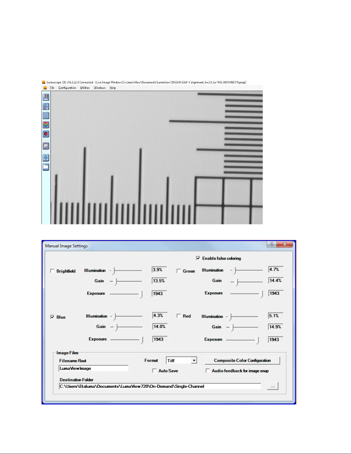
c. Click the first icon to adjust image parameters such as channel to be used, illumination, and Gain
and Exposure,

Lumascope 720-Series Startup Guide
5
Etaluma, Inc. | 3129 Tiger Run Court, Suite 112 | Carlsbad, CA 92010 | 760-298-2355 | www.etaluma.com
E. Objectives
1. To install or change objectives, loosen the deck clamp in front until the top deck can be lifted back to
expose the objective. When installing an objective do not overtighten. Remember to retighten the
deck clamp.
F. Calibration
1. Your Lumascope will need calibrating the first time it is used with any new computer. A 4x objective
and empty 1536-well plate has been included with the LS720 for calibration purposes.
2. Open the XYZ screen and check the box in the lower left hand corner labelled “Calibrate x/y for
microplate use”. When this is checked, the dialog will expand to show the calibration instructions and
buttons. Shown below is a graphic image of the widened dialog box.
3. With the 4x objective installed and the 1536 well plate in place, adjust focus until a well is seen.
Moving the focus slider up to about 75% should cause the image to pass through a focus and then this
can be optimized with slider adjustment or the arrow keys. Image brightness can be adjusted as focus
is found.
4. Now drive the stage with the Relative X/Y Move control until the red cross-hairs are centered on well
A1. This may require you to confirm that you are in the upper left corner well by moving above and left
of A1 to confirm it is indeed the corner well. When you are satisfied that you are centered in A1, press
Accept Calibration.
5. Uncheck the Calibrate button and choose Select Labware, choose 1536 well plate, and then select
Navigate to well and confirm that the instrument in centered in a few distant wells.

Lumascope 720-Series Startup Guide
6
Etaluma, Inc. | 3129 Tiger Run Court, Suite 112 | Carlsbad, CA 92010 | 760-298-2355 | www.etaluma.com
6. Replace the 4x objective with the one you would like to use for your experiment and be sure to select
the new objective under the Configuration drop down.
II. Software: Getting Started with Lumaview 720-Series
The following sections give directions for getting started with Lumaview 720-Series and are intended as a
quickstart guide only. Not all options are given and not all features may be explained in any particular
section. The complete User Guide for Lumaview 720-Series is contained in the Help Section after the
program is opened and is accessible by clicking on F1 or the Help dropdown menu/Contents. Becoming
familiar with the complete User Guide is a must in order to take advantage of the many features of this
program.
Using Lumaview 720- Summary
Control of your LS720 is divided into Manual operation and Automatic operation.
Manual operation is effected by the top four Icons on the left border. These icons are “Adjust Channels”,
“Position XYZ”, “Snap Picture”, “Snap Composite”and “Record Live Video”. With these controls, one is able
to perform single position, single time point acquisition of single or multiple channel images.
Automatic operation is controlled under the “P”or Protocol icon. Individual tabs in the Protocol screens
allow you to set up automatic versions of the manual configurations determined above. A Protocol consists
of the following tabs: Information, Acquisition, Image, XYZ, and Image Review. Each of these allow one to
configure the various settings to construct and save a Protocol for Automated operation.
A. Starting point conditions
1. Lumaview 720-Series has been downloaded to the computer.
2. The Lumascope 720 is connected to the computer via the two UBS power/communication cables.
3. Lumaview 720-Series is open and has been calibrated with a 4x objective and 1536-well microplate.
4. Sample to be imaged is present on the Lumascope 720 stage (and fluorescence shroud is over sample if
imaging involves fluorescence).
B. Illuminating the sample for brightfield
CAUTION: When any LEDs are turned on, do NOT look directly at the light. Be sure to turn off all LEDs at
the end of a viewing session so that any sample remaining on the stage is not photo-bleached.
1. For viewing in a typically lit area, ambient light is generally adequate to see brightfield. The light should
be as uniform as possible to prevent shadows or other dark or light areas. Overhead fluorescent
lighting can cause uneven brightness including a striped pattern; if observed, move the Lumascope or
partially shade the light to reduce unevenness across the sample. For optimal brightfield, use of the
light source of the Phase Contrast Accessory is recommended (see Section I.B above). Note: Because
the Lumascope 720 CMOS camera is monochromatic, brightfield images will be in black & white.
2. For viewing in a dark environment such as an incubator, a transmitted light source is needed.
Connecting the Phase Contrast Accessory to the Lumascope allows it to be controlled by Lumaview 720-
Series.

Lumascope 720-Series Startup Guide
7
Etaluma, Inc. | 3129 Tiger Run Court, Suite 112 | Carlsbad, CA 92010 | 760-298-2355 | www.etaluma.com
3. When using ambient light, move cursor over Live Image Window, right click, and select Exposure
Settings to open its dialog box. Start with Gain as low as possible and adjust Exposure so image has
gray tones. If using the Phase Contrast Accessory, move cursor over Live Image Window, right click, and
select Illumination Settings to open its dialog box. Right click again and select Exposure Settings to
open its dialog box. In Illumination box, check White LED. In general, to increase brightness, start with
Exposure at maximum and Gain as low as possible. Increase Illumination to desired brightness of gray
tones; if needed, increase the Gain gradually. To decrease brightness, turn Gain down to a minimal
level and then gradually decrease the Exposure. If still too bright, decrease the Illumination gradually
until image has gray tones with desired brightness.
C. Illuminating the sample for fluorescence
CAUTION: When any LEDs are turned on, do NOT look directly at the light. Be sure to turn off all LEDs at
the end of a viewing session so any sample remaining on the deck is not photo-bleached.
1. Click the first icon, opening the Image control screen.
2. In this menu check the LED of choice, e.g., F2 for green fluorescence is often chosen first due to its
typically bright signal. Start with Exposure at maximum and Gain as low as possible. Increase
Illumination to desired brightness. For dim samples, if Illumination is at maximum, increasing the Gain
can be used to get enough signal (but Gain will increase background as well).
3. If desired, check false coloring to see images in color. If more than one LED is turned on, images will be
gray scale and signal will be the sum of the selected channels.
D. Focusing
1. Move the Focus slider up to about 75% to begin looking for focus.
2. Use the slider and Z-arrows to get the best focus. Clicking on Expand icon on side bar of Live Image
Window zooms in on image so it fits the monitor screen horizontally and should help you to focus. If
necessary, increase or decrease LED brightness and/or Exposure and Gain.
E. Capturing images
1. Select the Output Format Default dropdown menu and select Output Format type desired. The TIFF
format is recommended due to several features as explained in Help/Image Types. Select or enter the
Demand Capture Filename Root for your image file names and desired Destination (e.g., a new folder
set up on the desktop).
2. When desired field has been illuminated and focused in Live Image Window, left click the camera icon
to capture the image.
3. A Save As dialog box will open. Confirm that the File Name is satisfactory and click Save. To autosave
the images without the Save As dialog box opening each time, check Auto Save.
4. For quick review of your last image, click the Folder icon on the left tool bar to launch Windows
Explorer, which will open the most recent Destination Folder.

Lumascope 720-Series Startup Guide
8
Etaluma, Inc. | 3129 Tiger Run Court, Suite 112 | Carlsbad, CA 92010 | 760-298-2355 | www.etaluma.com
F. Capturing composite images
1. Click the Composite icon in left tool bar of Live Image Window. A Composite Color Configuration dialog
box will open.
2. Select channels (e.g., F1, F2 and F3 for 3-color) and set LED % and Gain % for each based on viewing in
Section II.D above or previous experience. Manual entering of values is recommended because
checking Load Present Values will load only the LED % for each channel while Gain % will be the same
for all channels and correspond to the last determined channel.
3. Set LED Pre-Snap to 1 second (can be adjusted later). Choose Output Format Type (TIFF
recommended), Filename Root, and Destination Folder (e.g., folder set up on the desktop).
4. Click OK to start the image capture. Depending on the LEDs selected and Lumaview version, you should
see the LEDs come on in series and/or hear the images being captured (clicking sound).
5. The composite image made by combining the individual images together will appear in the Main
Window. The image file name at the top of the image includes the full path.
I. Recording live videos
1. The Video Record icon grabs every frame form the live image and puts them in a folder.
2. Click red circle icon in left side bar of Live Image Window to open Video Configuration dialog box.
3. Choose Filename Root, File Format (TIFF recommended), Destination Folder and if time-stamp is
desired. Click OK and images will start to record.
4. Click red circle icon again to stop. A dialog box will open stating that your images have been saved to
the Destination Folder and how to proceed.
5. To convert the captured images to video, a variety of options are available including Microsoft
Moviemaker, Apple iMovie, ImageJ, and CellProfiler.
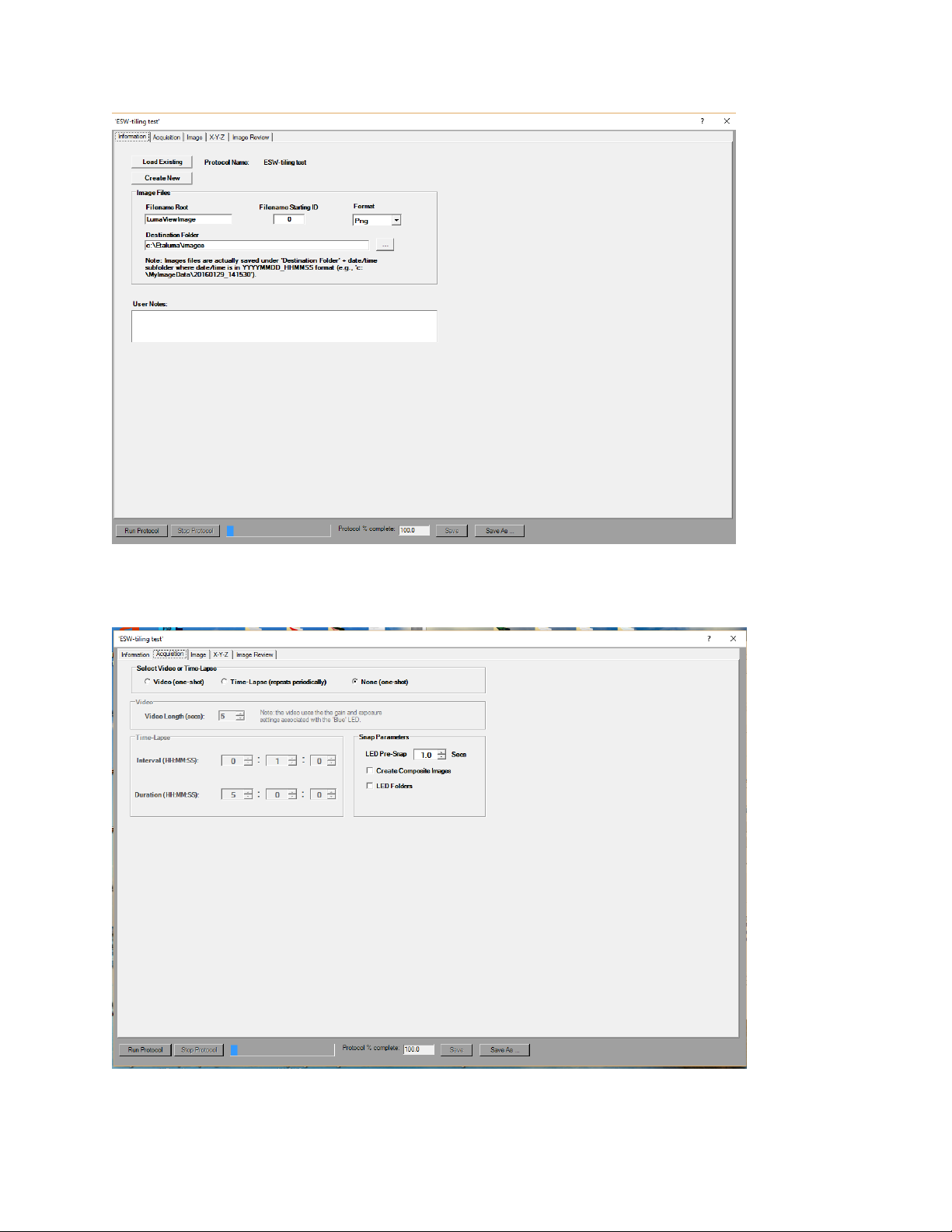
J. Setting up a Protocol
1. A Protocol allows an automated microscopy method to be configured, saved and run. It consists of
information about the channels, focus, and labware as well as timing and file details.
2. Clicking the “P” icon opens the Protocol interface.
3. The first tab of the Protocol is labelled Information and contains Protocol information including
data file path, file root, and image format.
Lumascope 720-Series Startup Guide
9
Etaluma, Inc. | 3129 Tiger Run Court, Suite 112 | Carlsbad, CA 92010 | 760-298-2355 | www.etaluma.com
4. The Acquisition Tab allows the selection of how images are gathered.

Lumascope 720-Series Startup Guide
10
Etaluma, Inc. | 3129 Tiger Run Court, Suite 112 | Carlsbad, CA 92010 | 760-298-2355 | www.etaluma.com
5. The next tab is Image
6. The XYZ tab is where the labware is selected and the wells or positions within that labware are also
selected. Autofocus settings and Tiling menus are also accessed from this tab. These are explained
below.

Lumascope 720-Series Startup Guide
11
Etaluma, Inc. | 3129 Tiger Run Court, Suite 112 | Carlsbad, CA 92010 | 760-298-2355 | www.etaluma.com
7. Autofocus Settings
8. Tile Selection
Lumascope 720-Series Startup Guide
12
Etaluma, Inc. | 3129 Tiger Run Court, Suite 112 | Carlsbad, CA 92010 | 760-298-2355 | www.etaluma.com
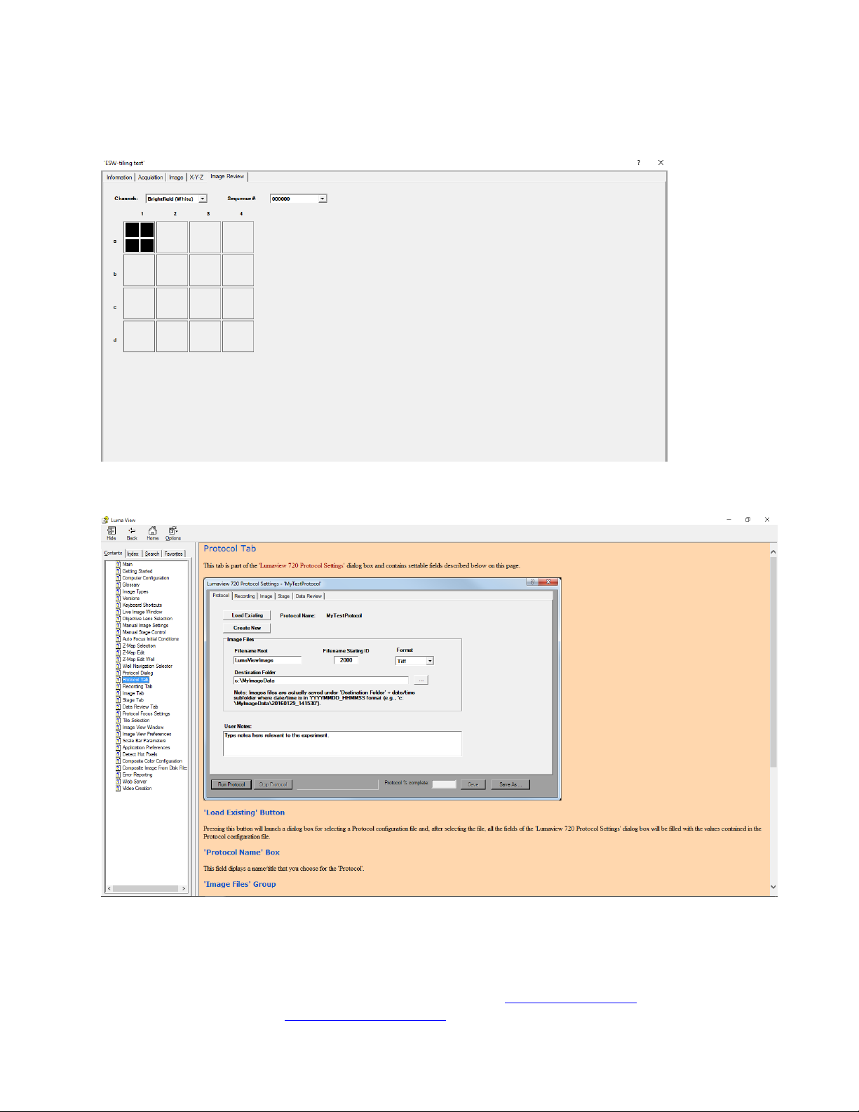
9. The Image Review tab shows thumbnail images, including tiles, for each well and channel as they
are acquired. Clicking on a well expands the image.
10. The Help Contents files contain descriptions of each screen and field within the menus.
For questions or comments, telephone the phone number below, email [email protected]m, or submit an inquiry
through the Etaluma website at http://etaluma.com/contact. An Etaluma representative will be happy to assist you.
Other Etaluma Laboratory Equipment manuals

Popular Laboratory Equipment manuals by other brands


Christ
Christ RVC 2-33 CDplus operating manual

Kodak
Kodak X-Omat 460 RA Processor installation instructions

Fritsch
Fritsch pulverisette 14 operating manual

Torrey Pines Logic
Torrey Pines Logic T15 user guide

Agilent Technologies
Agilent Technologies 700 Series user guide

OSTLING
OSTLING EMP/MODULMAT operating manual


