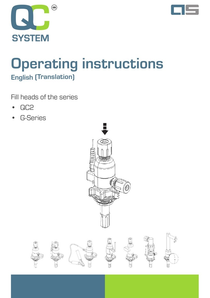
AS QC2 Series User manual

Operating instructions
(Translation)
Fill heads of the series
- QC2
- G-Series

EN
AS Strömungstechnik GmbH
www.asstroemungstechnik.de
Version date: 09/2020
2
Legal notice
The operating instructions in German are
the original operating instructions.
Revision status: A 09/2020, creation
If you have questions about the products,
please contact AS Strömungstechnik
GmbH (manufacturer) directly.
Copyright, address of the manufacturer
© Copyright by
AS Strömungstechnik GmbH
Elly-Beinhorn-Str. 7
73760 Ostldern
Germany
info@asstroemungstechnik.de
www.asstroemungstechnik.de
All rights reserved.
Printed in Germany
Legal notice

EN
AS Strömungstechnik GmbH
www.asstroemungstechnik.de
Version date: 09/2020
3
1 Contents
1 General information .............................................................................................. 4
1.1 Introduction ............................................................................................................. 4
1.2 Conventions ............................................................................................................ 4
1.3 Symbols and labels ................................................................................................. 5
1.4 Copyright protection ................................................................................................ 5
1.5 Guarantee and warranty ......................................................................................... 5
2 Safety ..................................................................................................................... 6
2.1 Intended use .......................................................................................................... 6
2.2 Improper use .......................................................................................................... 6
2.3 Responsibility of the user ....................................................................................... 6
2.4 General safety instructions ..................................................................................... 7
3 Setup/function ....................................................................................................... 8
3.1 Auxiliary tools .........................................................................................................11
4 Technicalspecications..................................................................................... 12
4.1 Fill head DH-R.../GH-R... ...................................................................................... 12
4.2 Fill head DH-_B.../GH-_B...................................................................................... 14
4.3 Fill head DH-A.../GH-A.......................................................................................... 16
4.4 Fill head DH-…-N2 / GH-…-N2............................................................................. 18
4.5 Fill head DH-_U… / GH-_U… ............................................................................... 20
4.6 Fill head DH-_J… / DH-J… / GH-_J… / GH-J… ................................................... 22
4.7 Ambient / operating temperature........................................................................... 24
4.8 Torques for dip tube closures................................................................................ 24
5 Assembly/commissioning.................................................................................. 25
5.1 Initial commissioning ............................................................................................. 25
5.2 Tests prior to assembly ......................................................................................... 28
5.3 Mounting the ll head ............................................................................................ 30
6 Operation ............................................................................................................. 34
6.1 Tests before each operation.................................................................................. 34
6.2 Tests during operation........................................................................................... 35
7 Troubleshooting .................................................................................................. 36
8 Disassembly ........................................................................................................ 38
8.1 Dismantling the ll head ........................................................................................ 38
9 Maintenance/disposal......................................................................................... 40
9.1 Cleaning the ll head............................................................................................. 40
9.2 Fill head maintenance ........................................................................................... 40
9.3 Returning ll heads ............................................................................................... 41
9.4 Fill head disposal .................................................................................................. 41
Contents

EN
AS Strömungstechnik GmbH
www.asstroemungstechnik.de
Version date: 09/2020
4
1 General information
1.1 Introduction
These operating instructions are only valid
for the products mentioned in the title.
The gures shown are only exemplary
illustrations. Depending on the equipment
and conguration, the actual appearance
of the ll head may vary.
These operating instructions convey im-
portant notes for the safe and efcient han-
dling of the products. They are part of the
products. The prerequisite for safe working
with the products is the compliance with all
specied safety instructions and directives.
The operating instructions refer to standard
versions. For special versions that are not
described in these operating instructions,
the basic information in these operating
instructions applies in conjunction with
additional special documentation.
The operating instructions are the basis for
all training courses that take place with the
products.
• Please read the operating instructions
carefully before using the products.
• Please read the safety instructions.
• Store the operating instructions in a
safe and accessible place during the
service life of the products.
• Pass the operating instructions to
any subsequent owner or user of the
products.
1.2 Conventions
In order to be able to optimally work with
the operating instructions, the following
clarications on typographical conventions
must be observed.
List
• Texts displayed in this way are bullet
points.
Handling instructions
1. Step 1 of the sequence of actions
2. Step 2 of the sequence of actions
3. Step 3 of the sequence of actions
The sequence of the work steps must be
adhered to.
Tip
» Indicates general information and
recommendations.
General information

EN
AS Strömungstechnik GmbH
www.asstroemungstechnik.de
Version date: 09/2020
5
1.3 Symbols and labels
The following symbols are used in these
operating instructions to depict hazards
and notes:
DANGER
Indicates a hazard which, if not avoided,
will result in death or serious injury.
WARNING
Indicates a hazard which, if not avoided,
could result in death or serious injury.
CAUTION
Indicates a hazard which, if not avoided,
could result in minor or moderate injury.
NOTE
Designates a situation that can result in
material damage.
1.4 Copyright protection
Despite all care taken, data and character-
istics can change – even at short notice.
We therefore do not assume any liability
or guarantee for the topicality, correctness
and completeness of the information.
Figures, graphics and texts as well as the
design of these operating instructions are
subject to copyright protection and other
protective laws. Duplication – also in ex-
cerpts – requires the prior written consent
of AS Strömungstechnik GmbH, if duplica-
tion is not legally permitted.
General information
1.5 Guarantee and warranty
AS Strömungstechnik GmbH assumes no
liability for errors or damage that occurred
due to improper handling of the products.
Improper handling is in particular in the
event of non-compliance with the operating
instructions, incorrect handling, negli-
gence, unauthorized replacement of parts
and other interventions.
The customer is responsible for testing the
chemical resistance of the ll heads and
their service life.
Fill heads and other products which have
come into contact with media/chemicals
(except ultra pure water) cannot be taken
back.
AS Strömungstechnik GmbH reserves the
right to make design changes due to fur-
ther development of AS products.
Our customer service is always available
even after the guarantee period has ex-
pired.

EN
AS Strömungstechnik GmbH
www.asstroemungstechnik.de
Version date: 09/2020
6
2 Safety
Please observe the following notes to pre-
vent malfunctioning, damage and injuries.
2.1 Intended use
The QC2 and G-Series ll heads are de-
signed for the clean and safe lling/recircu-
lation of neutral or inorganic liquid chemi-
cals into transport containers which do not
adversely affect the physical and chemical
properties of the materials and substances
of which the ll head used is composed.
The QC2 and G-Series conductive ll
heads are designed for the clean and safe
lling/recirculation of neutral or organic
liquid chemicals into transport containers
which do not adversely affect the physical
and chemical properties of the materials
and substances of which the ll head used
is composed. They are electrostatically
safe in the sense of the Cenelec Technical
Report TR 50404: 2003 and therefore ap-
plicable in zones 1 and 2 for liquids of the
entire explosion group IIA.
Fill heads may be used only in conjunction
with AS dip tubes of the series correspond-
ing to the ll head. Observe the operating
instructions of the dip tube.
The ll heads are designed for use with
pump systems.
For dispensing and withdrawal applica-
tions, refer to the operating instructions
for dispense heads of the corresponding
series.
2.2 Improper use
Any use other than the one described in
the Section “intended use” is deemed to
be inappropriate use. The operator of the
products shall be solely responsible for any
resulting damage.
2.3 Responsibility of the user
Operator means any natural or legal per-
son who operates or controls the device or
makes it accessible to third parties for use
and who is responsible for the safety of the
user or third parties.
• In particular, observe the general
safety and occupational safety regula-
tions of the BG Chemie in Germany or
the responsible regional professional
association for chemistry and health
(e.g. OSHA in the United States), the
applicable technical rules for haz-
ardous substances, the Hazardous
Substances Ordinance, the CLP Or-
dinance, the company own standard
operating procedures (SOPs), as
well as the regulations of the ATEX
Directive, the technical guidelines
“Flammable liquids” and the explosion
protection guidelines of the BG Che-
mie in Germany or the responsible
regional association / authority for
applications in hazardous areas.
• If ammable liquids are “splash lled”
into the container, the applicable
national and international regula-
tions and guidelines must also be
observed (e.g. BetrSichV incl. TRBS
2153, 4/2009 (Germany), Cenelec
Technical Report TR 50404: 2003
(EU), IEC 60079-32 (international),
Safety

EN
AS Strömungstechnik GmbH
www.asstroemungstechnik.de
Version date: 09/2020
7
JNIOSH-TR-No.42 2007 (Japan),
NFPA Recommended Practice on
Static Electricity (USA). It must also be
checked whether a correspondingly
long dip tube can be used for the re-
turn / lling into the container, which
enables lling below the liquid level.
• These operating instructions do not
replace the company’s own standard
operating procedures (SOPs).
• Wear appropriate protective clothing
when handling chemical substances.
• Ensure that the ll heads are not used
after the maximum period of use has
expired. The duration of use depends
on the chemicals used.
• Before using the products, check the
materials for their chemical resistance.
2.4 General safety instructions
• Always observe the safety data sheets
(SDS) of the chemicals used.
• Only use cleaned products. The prod-
ucts described in these operating
instructions have been cleaned in an
ultrasonic bath at the factory.
• Only use products for which the chem-
ical resistance of the components is
guaranteed.
Safety

EN
AS Strömungstechnik GmbH
www.asstroemungstechnik.de
Version date: 09/2020
8
3 Setup/function
In the QC2 and G-Series, the following ll
heads are available:
Abbrevi-
ation
Description
DH-R...
GH-R...
Fill head with/without check
valve
• Standard,
• electrically conductive.
DH-_B...
GH-_B... Fill head with limit switch
DH-A...
GH-A...
Fill head with manual shut-off
valve
• Plug valve (turncock)
• Ball valve
DH-J...
DH-_J...
GH-J...
GH-_J...
Fill head with mixing nozzle
DH-...-N2
GH-...-N2
Fill head with second vent port
for N2-blanketing
DH-_U...
GH-_U... Fill head with overlling sensor
» Fill head versions can be combined
with each other.
For example, a QC2 Fill head can also
have a check valve, a limit switch and
a overlling sensor (DH-RBU-...).
The electrically conductive version
with limit switch, manual shut-off valve
or second vent port is also available.
Depending on the design, the ll head may
look slightly different.
Setup/function

EN
AS Strömungstechnik GmbH
www.asstroemungstechnik.de
Version date: 09/2020
9
Setup/function
No. Object
1Liquid line connection
2Tightening nut (incl. red markings)
3 Code disk
4Anti-rotation clip (red)
5 Main body
6 Vent port
standard: NPT3/8" female thread
(from 11/2019), on the Figure with
screwed-in are adapter.
7 Locking pin (set screw)
8Top connection (vertical or horizontal)
9Check valve (depending on model)
10 Vent channel
11 Liquid channel
12 Limit switch (optional)

EN
AS Strömungstechnik GmbH
www.asstroemungstechnik.de
Version date: 09/2020
10
The ll head is generally equipped with:
• Liquid line connection to inlet of uid
pump line connection
• Vent line connection
• Code disk
• Tightening nut with red anti-rotation
clip
• Standard connection to mating dip
tube
Depending on the option, the uid ow rate
in the liquid channel can be controlled by
a check valve, a plug valve (turncock) or a
ball valve.
The check valve ensures that there is no
ow back after transfer is complete and
there is no spill at disconnection. As soon
as the pump is activated, the check valve
opens. When the pump is switched off, the
pressure in the lling line is reduced and
the check valve closes.
The optional limit switch ensures that the
ll head is correctly mounted. The lling
process can only be started after the re-
lease signal from the limit switch.
» The incorporation of the limit switch
requires professional installation to
integrate the signals into the system
control (PLC) to properly operate.
To ll ammable or highly ammable
chemicals into a container, there is an
electrically conductive version of the ll
head and the dip tube.
» The MOC of electrically conductive
plastic ll heads and dip tubes is al-
ways black in color due to the carbon
additive.
WARNING
Danger due to static charge.
Statically charged chemicals or ll
heads, dip tubes, etc. can cause sparks
to arc creating an ignition source.
• Ground the dip tube and ll head
properly.
Setup/function

EN
AS Strömungstechnik GmbH
www.asstroemungstechnik.de
Version date: 09/2020
11
Technicalspecications
3.1 Auxiliary tools
The required auxiliary tools are listed be-
low. For further details, please refer to the
corresponding data sheet and our website.
Docking station (for wall mounting)
Series Item no. Note
QC2 RDC -89740 incl. bottle
QC2
conduc-
tive.
RDC -89740 -CD
without shelf
for accesso-
ries
G-Se-
ries RDC-89750 incl. bottle
G-Se-
ries con-
ductive
RDC-89754
without shelf
for accesso-
ries
Universal bung wrench
Series Item no. Note
QC2 RDH-79005 PVDF
QC2
conduc-
tive.
RDH-79003-CD electrically
conductive
G-Se-
ries RDH-79010 PVDF
G-Se-
ries con-
ductive
RDH-79009 electrically
conductive
Torque tool
The torque tool comes with torque wrench
and attachment.
Series Item no.
QC2 DH-Z-2-0001-02
G-Series DH-Z-G-0001-02
24mm
6 point socket

EN
AS Strömungstechnik GmbH
www.asstroemungstechnik.de
Version date: 09/2020
12
4 Technicalspecications
4.1 Fill head DH-R.../GH-R...
Characteristic Value Figure
Dimensions See the corresponding
data sheet for the ll head.
The ll heads shown here are only exemplary representations.
Depending on the equipment and conguration, the actual ll
head may vary in appearance
Weight
Tightening torque
[Nm]
QC2: 2.6
G-Series: 2.6
Flow rates
[l/min]
QC2:
• max. 25 (with check
valve)
• max. 60 (without check
valve)
G-Series:
• max. 100 (with check
valve)
• max. 150 (without check
valve)
Opening pressure
check valve [bar]
QC2: 0.10
G-Series: 0.05
Period of use Depending on chemical
resistance
Standard: 3 years
Technicalspecications

EN
AS Strömungstechnik GmbH
www.asstroemungstechnik.de
Version date: 09/2020
13
Materials (wetted components)
Characteristic Value
Housing variants Standard (natural): PE-HD, PVDF, PCTFE
Conductive: PP (black), PVDF (black), PFA (black), stainless steel
O-ring variants Standard: Peruor elastomer (Kalrez®)
As an alternative: FPM/FKM, EPDM
Materials (non-wetted components)
Characteristic Value
Anti-rotation clip PVC (red)
O-ring on code
disk
Standard: FKM
As an alternative: EPDM, Kalrez®
Other components Standard: PVDF,
As an alternative: PFA, on request
Connections
Characteristic Value
Connection vari-
ants liquid
Flare: 3/8“, 1/2“, 3/4“, 1“, 1 1/4“
Hose connector: 1/2“, 3/4“, 1“
FNPT/MNPT: 1/2“, 3/4“, 1“
G-thread: 1/2“
Others on request (e.g. Tri-Clamp, Camlock, Pillar, Grundfos)
Connection
gas
QC2: NPT 3/8" female thread (since November 2018)
G-Series: NPT 1/2" female thread (since November 2018)
Optional adapters, e.g. Flare adaptors
» Further information on the ll heads can be found in the corresponding data sheets.
Possible other versions are available on request.
Technicalspecications

EN
AS Strömungstechnik GmbH
www.asstroemungstechnik.de
Version date: 09/2020
14
4.2 Fill head DH-_B.../GH-_B..
Characteristic Value Figure
Dimensions See the corresponding
data sheet for the ll head.
The ll heads shown here are only exemplary representations.
Depending on the equipment and conguration, the actual ll
head may vary in appearance
Weight
Tightening torque
[Nm]
QC2: 2.6
G-Series: 2.6
Flow rates
[l/min]
QC2:
• max. 25 (with check
valve)
• max. 60 (without check
valve)
G-Series:
• max. 100 (with check
valve)
• max. 150 (without check
valve)
Opening pressure
check valve (if
applicable) [bar]
QC2: 0.10
G-Series: 0.05
Period of use Depending on chemical
resistance
Standard: 3 years
» For electrical data, connection diagram and further information on integration, refer to
the separate data sheet of the sensor.
Technicalspecications

EN
AS Strömungstechnik GmbH
www.asstroemungstechnik.de
Version date: 09/2020
15
Materials (wetted components)
Characteristic Value
Housing variants Standard (natural): PE-HD, PVDF, PCTFE
Conductive: PP (black), PVDF (black), PFA (black)
O-ring variants Standard: Peruor elastomer (Kalrez®)
As an alternative: FPM/FKM, EPDM
Release pin (limit
switch)
Standard: Magnet encapsulated in PVDF
As an alternative: Magnet encapsulated in PCTFE
Materials (non-wetted components)
Characteristic Value
Anti-rotation clip PVC (red)
O-ring on code
disk
Standard: FKM
As an alternative: EPDM, Kalrez®
Other components Standard: PVDF,
As an alternative: PFA, on request
Sensor See data sheet of the sensor
Connections
Characteristic Value
Connection vari-
ants liquid
Flare: 3/8“, 1/2“, 3/4“, 1“, 1 1/4“
Hose connector: 1/2“, 3/4“, 1“
FNPT/MNPT: 1/2“, 3/4“, 1“
G-thread: 1/2“
Others on request (e.g. Tri-Clamp, Camlock, Pillar, Grundfos)
Connection
gas
QC2: NPT 3/8" female thread (since November 2018)
G-Series: NPT 1/2" female thread (since November 2018)
Optional adapters, e.g. Flare adaptors
» Further information on the ll heads can be found in the corresponding data sheets.
Possible other versions are available on request.
Technicalspecications

EN
AS Strömungstechnik GmbH
www.asstroemungstechnik.de
Version date: 09/2020
16
4.3 Fill head DH-A.../GH-A..
Characteristic Value Figure
Dimensions See the corresponding
data sheet for the ll head.
(1): Plug valve (turncock)
(2): Ball valve
The ll heads shown here are only exemplary representations.
Depending on the equipment and conguration, the actual ll
head may vary in appearance
Weight
Tightening torque
[Nm]
QC2: 2.6
G-Series: 2.6
Flow rates
[l/min]
QC2:
• max. 60
G-Series:
• max. 150
Period of use Depending on chemical
resistance
Standard: 3 years
Technicalspecications

EN
AS Strömungstechnik GmbH
www.asstroemungstechnik.de
Version date: 09/2020
17
Materials (wetted components)
Characteristic Value
Housing variants Standard (natural): PE-HD, PVDF, PCTFE
Conductive: PP (black), PVDF (black), PFA (black), stainless steel
O-ring variants Standard: Peruor elastomer (Kalrez®)
As an alternative: FPM/FKM, EPDM
Ball valve For PE-HD housings
• Standard: PP-H with FPM o-rings
• As an alternative: PP-H with EPDM o-rings, PP-H with Kalrez o-rings
For PVDF housings
• Standard: PVDF with FPM o-rings
• As an alternative: PVDF with EPDM o-rings, PVDF with Kalrez o-rings
Materials (non-wetted components)
Characteristic Value
Anti-rotation clip PVC (red)
o-ring on code
disk
Standard: FKM
As an alternative: EPDM, Kalrez®
Other components Standard: PVDF,
As an alternative: PFA, on request
Connections
Characteristic Value
Connection vari-
ants liquid
Flare: 3/8“, 1/2“, 3/4“, 1“, 1 1/4“
Hose connector: 1/2“, 3/4“, 1“
FNPT/MNPT: 1/2“, 3/4“, 1“
G-thread: 1/2“
Others on request (e.g. Tri-Clamp, Camlock, Pillar, Grundfos)
Connection
gas
QC2: NPT 3/8" female thread (since November 2018)
G-Series: NPT 1/2" female thread (since November 2018)
Optional adapters, e.g. Flare adaptors
» Further information on the ll heads can be found in the corresponding data sheets.
Possible other versions are available on request.
Technicalspecications

EN
AS Strömungstechnik GmbH
www.asstroemungstechnik.de
Version date: 09/2020
18
Technicalspecications
4.4 Fill head DH-…-N2 / GH-…-N2
Characteristic Value Figure
Dimensions See the corresponding
data sheet for the ll head.
N2-Connection
N2-Connection
Vent port
Vent port
The fill heads shown here are only exemplary
representations. Depending on the equipment and
conguration, the actual ll head may vary in appearance
Weight
Tightening torque
[Nm]
QC2: 2.6
G-Series: 2.6
Flow rates
[l/min]
QC2:
• max. 25 (with check
valve)
• max. 60 (without check
valve)
G-Series:
• max. 100 (with check
valve)
• max. 150 (without check
valve)
Opening pressure
check valve (if appli-
cable) [bar]
QC2: 0.10
G-Series: 0.05
Period of use Depending on chemical
resistance
Standard: 3 years

EN
AS Strömungstechnik GmbH
www.asstroemungstechnik.de
Version date: 09/2020
19
Technicalspecications
Materials (wetted components)
Characteristic Value
Housing variants Standard (natural): PE-HD, PVDF, PCTFE
Conductive: PP (black), PVDF (black), PFA (black)
O-ring variants Standard: Peruor elastomer (Kalrez®)
As an alternative: FPM/FKM, EPDM
N2-tube Standard: PE-LD
As an alternative: PFA
Materials (non-wetted components)
Characteristic Value
Anti-rotation clip PVC red
O-ring on code
disk
Standard: FKM
As an alternative: EPDM, Kalrez®
Other components Standard: PVDF,
As an alternative: PFA, on request
Connections
Characteristic Value
Connection vari-
ants
liquid
Flare: 3/8“, 1/2“, 3/4“, 1“, 1 1/4“
Hose connector: 1/2“, 3/4“, 1“
FNPT/MNPT: 1/2“, 3/4“, 1“
G-thread: 1/2“
Others on request (e.g. Tri-Clamp, Camlock, Pillar, Grundfos)
Connection
gas
QC2: NPT 3/8“ female thread (since November 2018)
G-Series: NPT 1/2“ female thread (since November 2018)
Optional adapters, e.g. Flare adaptors
N2-connection QC2: Flare ¼“, further upon on request
G-Series: Flare 3/8“, further upon on request
» Further information on the ll heads can be found in the corresponding data sheets.
Possible other versions are available on request.

EN
AS Strömungstechnik GmbH
www.asstroemungstechnik.de
Version date: 09/2020
20
Technicalspecications
4.5 Fill head DH-_U… / GH-_U…
Characteristic Value Figure
Dimensions See the corresponding
data sheet for the ll head.
Vent port to connect vent line
Sensor
Sensor
Vent port to connect
vent line
The fill heads shown here are only exemplary
representations. Depending on the equipment and
conguration, the actual ll head may vary in appearance
Weight
Tightening torque
[Nm]
QC2: 2.6
G-Series: 2.6
Flow rates
[l/min]
QC2:
• max. 25 (with check
valve)
• max. 60 (without check
valve)
G-Series:
• max. 100 (with check
valve)
• max. 150 (without check
valve)
Opening pressure
check valve (if appli-
cable) [bar]
QC2: 0.10
G-Series: 0.05
Period of use Depending on chemical
resistance
Standard: 3 years
» For electrical data, connection diagram and further information on integration, refer to
the separate data sheet of the sensor.
Other manuals for QC2 Series
1
This manual suits for next models
13
Table of contents
Other AS Laboratory Equipment manuals
Popular Laboratory Equipment manuals by other brands

CEM
CEM MARS Series installation guide

Iconic
Iconic VF1 instruction manual

Philadelphia Scientific
Philadelphia Scientific iBos Charger-Splitter Operation manual

Centurion Scientific
Centurion Scientific Pro-Research instruction manual

Agilent Technologies
Agilent Technologies 8860 Site preparation guide

IKA
IKA VC 10 lite operating instructions